EP0324620A1 - Angular velocity sensor - Google Patents
Angular velocity sensor Download PDFInfo
- Publication number
- EP0324620A1 EP0324620A1 EP89300266A EP89300266A EP0324620A1 EP 0324620 A1 EP0324620 A1 EP 0324620A1 EP 89300266 A EP89300266 A EP 89300266A EP 89300266 A EP89300266 A EP 89300266A EP 0324620 A1 EP0324620 A1 EP 0324620A1
- Authority
- EP
- European Patent Office
- Prior art keywords
- rate sensor
- gas rate
- output signal
- gas
- pair
- Prior art date
- Legal status (The legal status is an assumption and is not a legal conclusion. Google has not performed a legal analysis and makes no representation as to the accuracy of the status listed.)
- Granted
Links
Images

Classifications
-
- G—PHYSICS
- G01—MEASURING; TESTING
- G01C—MEASURING DISTANCES, LEVELS OR BEARINGS; SURVEYING; NAVIGATION; GYROSCOPIC INSTRUMENTS; PHOTOGRAMMETRY OR VIDEOGRAMMETRY
- G01C19/00—Gyroscopes; Turn-sensitive devices using vibrating masses; Turn-sensitive devices without moving masses; Measuring angular rate using gyroscopic effects
- G01C19/58—Turn-sensitive devices without moving masses
Definitions
- the present invention relates to a gas rate sensor which is capable of detecting angular velocity.
- a gas rate sensor provides an output signal in response to any difference between the output signals supplied from a pair of thermal sensing elements. Such a different appears when the gas flow ejected from a gas nozzle deviates, to flow more on one of the thermal sensing elements than on the other, due to the influence on the gas flow of an applied motion the angular velocity of which is to be determined in terms of its magnitude and direction.
- the angular velocity is determined by detecting a small imbalance in the heat dissipation from the pair of thermal sensing elements due to the deviation of the gas flow, and therefore the surrounding temperature change significantly reduces the sensitivity of the gas rate sensor. This necessitates the use of temperature compensating means in the gas rate sensor.
- the gas rate sensor is subjected to forced heating by using appropriate heaters, and the temperature within the gas rate sensor is detected by appropriate temperature sensors, and the temperature within the gas rate sensor is controlled to keep it constant.
- the sensitivity of the gas rate sensor and the offset value remain too unstable to provide an accurate output signal until the temperature within the gas rate sensor has reached a stable condition after connecting the electric heater to an associated power supply. In fact, no satisfactory gas temperature control has yet been attained in a gas rate sensor.
- the present invention seeks to provide a gas rate sensor which is capable of correcting the gas rate sensor output signal in a way so as to account for an instantaneous temperature change within the gas rate sensor, allowing the temperature within the gas rate sensor to vary.
- a gas rate sensor which provides an output signal in response to any difference between the output signals from a pair of thermal sensing elements due to the force which an angular velocity exerts on the gas flow ejected over the pair of thermal sensing elements, from an associated nozzle, in which said gas rate sensor is equipped with: means to effect temperature compensation of the gas rate sensor output signal by substracting an offset value from the gas rate sensor output signal; means to determine the resistances of the pair of thermal sensing elements; means to detect the situation in which the resistances of the pair of thermal sensing elements increase or decrease simultaneously; means to make a decision as to whether or not the gas rate sensor output signal remains within a predetermined tolerance with respect to the offset signal when such a situation is detected; and means to permit the gas rate sensor output to be used as a new offset value when the gas rate sensor output signal remains within said predetermined tolerance.
- the casing 1 of the gas rate sensor is open at one and, and is closed at the other end.
- the casing 1 has three longitudinal ridges 120 degrees apart from each other on its inner surface. When the gas rate sensor body 4 is put in the casing 1, these longitudinal ridges define three longitudinal channels 3.
- the gas rate sensor body 4 is composed of a holder section 5, a neck section 6 and a cylinder section 7.
- the holder section 5 serves to confine the gas within the casing 1.
- the holder section 5 has a pump compartment 8, and the pump compartment 8 contains a diaphragm type piezoelectric pump 9.
- gas is drawn in the longitudinal channels 3 through the inlets 10 of the holder section 5.
- the gas is drawn into a sensor compartment 13 in the form of laminar flow.
- the gas flows over a pair of heating wires 14a and 14b, which are used as thermal sensing elements and are positioned downstream of the sensor compartment 13.
- the pair of heating wires 14a and 14b are located symmetrically with respect to the center line o-o of the nozzle 11, as seen from Figure 4.
- the gas is ejected fromthe nozzle 11, flowing straight along the center line o-o, and exposing each of the heating wires 14a and 14b to an equal gas flow rate, and hence cooling each heating wire equally.
- a printed board 16 of the amplifier circuit 15 is attached to the flange 2 of the casing 1 as seen from Figure 3.
- a hollow cylinder 17 contains the whole structure of the gas rate sensor.
- heating wires 14a and 14b which have the same temperature-to-resistance characteristic.
- two heating wires 14a and 14b have different characteristics as shown in Figure 5. Therefore, even if the gas rate sensor has no angular velocity, the gas rate sensor output signal cannot be zero. Also, an error will be caused in detecting the angular velocity of the gas rate sensor because these heating wires do not have the same temperature-to-resistance characteristic.
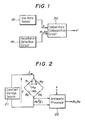
- Figure 1 shows a gas rate sensor system according to one embodiment of the present invention. It comprises a gas rate sensor 18, a resistance detection circuit 19 for detecting the resistances R1 and R2 of the heating wires 14a and 14b used in the gas rate sensor 18, and a temperature compensation circuit for effecting a temperature compensation of the gas rate sensor output x in response to the detected heating wire resistances R1 and R2 and the gas rate sensor output signal x.
- Figure 2 shows the structure of the resitance detection circuit 19 comprising: a bridge made from the heating wires 14a and 14b and two known resistances Ra and Rb; another known resistance series-connected to the bridge; and a constant voltage source 21, producing a voltage E, connected across the bridge and the resistance Rc.
- An arithmetic processor 22 is connected across the series resistance Rc, and the arithmetic processor 22 uses the voltage E1 appearing across the series resistance Rc, and the gas rate sensor output signal x to carry out the following arithmetic operation for determining the resitances R1 and R2 of the heating wires 14a and 14b;
- the resistance R1 and R2 of the heating wires 14a and 14b can be determined from Equation (8) and (9) in real-time.
- the temperature compensation circuit 20 corrects the gas rate sensor output signal x by substracting from the gas rate sensor output signal x an offset value which is initially stored in the temperature compensation circuit 20 in accordance with the characteristics of the heating wires 14a and 14b in the gas rate sensor 18. Then, the temperture compensation circuit 20 makes a decision as to whether or not the gas rate sensor output signal x remains within a predetermined tolerance with respect to the offset value, when the resistances R1 and R2 detected by the resistance detection circuit 19 increase or decrease together. If the gas rate sensor output signal x remains within the predetermined tolerance the temperature compendation circuit 20 will carry out correction by using the current gas rate sensor output signal x as a new offset value in place of the old one so that the gas rate sensor output signal x tends to zero.
- the temperature compensation circuit 20 will not change the offset value, regarding the gas rate sensor as having an angular velocity.
- a gas rate sensor system determines the resistances of the pair of heating wires of the gas rate sensor in order to detect the temperature change of the surrounding atmosphere of the heating wires in terms of the simultaneous increase or decrease of the pair of heating wire resistances. It is presumed that the gas rate sensor has no angular velocity when the gas rate sensor output signal remains within a given tolerance, such that the current gas rate sensor output signal is nearly equal to the predetermined offset value. The current gas rate sensor output signal is then used as a offset value. Thus, appropriate temperature compensation of the gas rate sensor output signal can be made, to account for the temperature change of the atmosphere surrounding the pair of heating wires.
- the offset value can be updated without stopping the car for that purpose.
Abstract
Description
- The present invention relates to a gas rate sensor which is capable of detecting angular velocity.
- In general, a gas rate sensor provides an output signal in response to any difference between the output signals supplied from a pair of thermal sensing elements. Such a different appears when the gas flow ejected from a gas nozzle deviates, to flow more on one of the thermal sensing elements than on the other, due to the influence on the gas flow of an applied motion the angular velocity of which is to be determined in terms of its magnitude and direction.
- The angular velocity is determined by detecting a small imbalance in the heat dissipation from the pair of thermal sensing elements due to the deviation of the gas flow, and therefore the surrounding temperature change significantly reduces the sensitivity of the gas rate sensor. This necessitates the use of temperature compensating means in the gas rate sensor.
- In an attempt to reduce the adverse effects caused by the surrounding temperature the gas rate sensor is subjected to forced heating by using appropriate heaters, and the temperature within the gas rate sensor is detected by appropriate temperature sensors, and the temperature within the gas rate sensor is controlled to keep it constant.
- Disadvantageously, the sensitivity of the gas rate sensor and the offset value remain too unstable to provide an accurate output signal until the temperature within the gas rate sensor has reached a stable condition after connecting the electric heater to an associated power supply. In fact, no satisfactory gas temperature control has yet been attained in a gas rate sensor.
- With the above in mind the present invention seeks to provide a gas rate sensor which is capable of correcting the gas rate sensor output signal in a way so as to account for an instantaneous temperature change within the gas rate sensor, allowing the temperature within the gas rate sensor to vary.
- According to the present invention there is provided a gas rate sensor which provides an output signal in response to any difference between the output signals from a pair of thermal sensing elements due to the force which an angular velocity exerts on the gas flow ejected over the pair of thermal sensing elements, from an associated nozzle, in which said gas rate sensor is equipped with: means to effect temperature compensation of the gas rate sensor output signal by substracting an offset value from the gas rate sensor output signal; means to determine the resistances of the pair of thermal sensing elements; means to detect the situation in which the resistances of the pair of thermal sensing elements increase or decrease simultaneously; means to make a decision as to whether or not the gas rate sensor output signal remains within a predetermined tolerance with respect to the offset signal when such a situation is detected; and means to permit the gas rate sensor output to be used as a new offset value when the gas rate sensor output signal remains within said predetermined tolerance.
- For a better understanding of the present invention, and to show how it may be carried into effect, reference will now be made, by way of example, to the accompanying drawings, in which:
- Figure 1 shows diagrammatically the gas rate sensor equipped with temperature compensation means.
- Figure 2 is a circuit diagram of a resistance detection circuit;
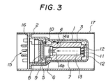
- Figure 3 is a longitudinal section of the gas rate sensor;
- Figure 4 shows how the gas flow deviates when the gas rate sensor is moved at an angular velocity to be determined; and
- Figure 5 is a graph representing the temperature-to-resistance characteristics of a pair of heating wires.
- Referring to Figure 3, the casing 1 of the gas rate sensor is open at one and, and is closed at the other end. The casing 1 has three longitudinal ridges 120 degrees apart from each other on its inner surface. When the gas
rate sensor body 4 is put in the casing 1, these longitudinal ridges define threelongitudinal channels 3. - As seen from the drawing, the gas
rate sensor body 4 is composed of aholder section 5, aneck section 6 and acylinder section 7. Theholder section 5 serves to confine the gas within the casing 1. Theholder section 5 has apump compartment 8, and thepump compartment 8 contains a diaphragm typepiezoelectric pump 9. When thepump 9 works, gas is drawn in thelongitudinal channels 3 through theinlets 10 of theholder section 5. After passing through acentral nozzle 11 and rectifyingapertures 12, positioned around the nozzle in the end of thecylinder section 7, the gas is drawn into asensor compartment 13 in the form of laminar flow. Then, the gas flows over a pair ofheating wires sensor compartment 13. Thereafter, the gas flows into thepump compartment 8, where it is directed to thelongitudinal channels 3 by pumping. The pair ofheating wires nozzle 11, as seen from Figure 4. When no force is applied to the gas rate sensor in a lateral direction, the gas is ejected fromthenozzle 11, flowing straight along the center line o-o, and exposing each of theheating wires - When a lateral force is applied to the gas rate sensor to cause it to move at an angular velocity, the gas flow will deviate from the center line o-o as shown in broken lines. The amount of deviation is indicated by "ε". As a result, the gas flows more on
heating wire 14a than onheating wire 14b, thus causing unbalanced outputs from the two heating wires. Then, a signal representing the difference between the unbalanced outputs will appear at the output terminal of the gas rate sensor, and the output signal will be amplifed by anamplifier circuit 15. The polarity and amplitude of the amplified signal represents the direction and magnitude of the angular velocity of the gas rate sensor, respectively. - A printed
board 16 of theamplifier circuit 15 is attached to theflange 2 of the casing 1 as seen from Figure 3. Ahollow cylinder 17 contains the whole structure of the gas rate sensor. - A singal appearing at the output terminal of the gas rate sensor is likely to vary with surrounding temperature. The gas rate sensor output signal x is given by:
X = (R₂ (T)/R₁ (T)) - 1
where R₁ (T) stands from the resistance of theheating wire 14a at temperature T and R₂ (T) stands for the resistance of theheating wire 14b at temperature T. - If two
heating wires - However, it is difficult to select and use a pair of
heating wires heating wires - Necessary temperature compensation of the gas rate sensor output signal x will be effected according to the present invention as follows:
- Figure 1 shows a gas rate sensor system according to one embodiment of the present invention. It comprises a
gas rate sensor 18, aresistance detection circuit 19 for detecting the resistances R₁ and R₂ of theheating wires gas rate sensor 18, and a temperature compensation circuit for effecting a temperature compensation of the gas rate sensor output x in response to the detected heating wire resistances R₁ and R₂ and the gas rate sensor output signal x. Figure 2 shows the structure of theresitance detection circuit 19 comprising: a bridge made from theheating wires constant voltage source 21, producing a voltage E, connected across the bridge and the resistance Rc. Anarithmetic processor 22 is connected across the series resistance Rc, and thearithmetic processor 22 uses the voltage E₁ appearing across the series resistance Rc, and the gas rate sensor output signal x to carry out the following arithmetic operation for determining the resitances R₁ and R₂ of theheating wires - The following equation hold for the resistance circuit of Figure 2:
E-E₁ = (R₁ + R₂) I₁ = (Ra + Rb) I₂ (2)
I₁ + I₂ = I (3)
E₁ = I.Rc (4) - From equations (2), (3) and (4) the following equation is derived:
R1+R₂ = Rc(E-E₁)(Ra + Rb)/E₁(Ra + Rb)-Rc(E-E₁) (5) - If (R₁+ R₂) is represented by y, then
(R₁ + R₂) = y (6) - The gas rate sensor output signal x is given by Equation (1) as follows:
x = (R₂/R₁) - 1 (7) - Thus, from Equations (5), (6) and (7) R₁ and R₂ are derived as follows:
R₁ = y/(x+2) (8)
R₂ = y.(x+1)/(x+2) (9) - By detecting the voltage E₁ across the resistance Rc the resistance R₁ and R2 of the
heating wires - The
temperature compensation circuit 20 corrects the gas rate sensor output signal x by substracting from the gas rate sensor output signal x an offset value which is initially stored in thetemperature compensation circuit 20 in accordance with the characteristics of theheating wires gas rate sensor 18. Then, thetemperture compensation circuit 20 makes a decision as to whether or not the gas rate sensor output signal x remains within a predetermined tolerance with respect to the offset value, when the resistances R₁ and R₂ detected by theresistance detection circuit 19 increase or decrease together. If the gas rate sensor output signal x remains within the predetermined tolerance thetemperature compendation circuit 20 will carry out correction by using the current gas rate sensor output signal x as a new offset value in place of the old one so that the gas rate sensor output signal x tends to zero. - If the gas sensor output signal x lies outside the predetermined tolerance the
temperature compensation circuit 20 will not change the offset value, regarding the gas rate sensor as having an angular velocity. - As apparent from above, a gas rate sensor system according to the present invention determines the resistances of the pair of heating wires of the gas rate sensor in order to detect the temperature change of the surrounding atmosphere of the heating wires in terms of the simultaneous increase or decrease of the pair of heating wire resistances. It is presumed that the gas rate sensor has no angular velocity when the gas rate sensor output signal remains within a given tolerance, such that the current gas rate sensor output signal is nearly equal to the predetermined offset value. The current gas rate sensor output signal is then used as a offset value. Thus, appropriate temperature compensation of the gas rate sensor output signal can be made, to account for the temperature change of the atmosphere surrounding the pair of heating wires.
- If a car is equipped with a gas rate sensor system according to the present invention for detecting any change in its direction of movement, the offset value can be updated without stopping the car for that purpose.
Claims (2)
means to effect temperature compensation of the gas rate sensor output signal by substracting an offset value from the gas rate sensor output signal;
means to determine the resistances of the pair of thermal sensing elements (14a, 14b);
means to detect the situation in which the resistances of the pair of thermal sensing elements (14a, 14b) increase or decrease simultaneously;
means to make a decision as to whether or not the gas rate sensor output signal remains within a predetermined tolerance with respect to the offset value when such a situation is detected; and
means to permit the gas rate sensor output signal to be used as a new offset value when the gas rate sensor output signal remains within said predetermined tolerance.
Applications Claiming Priority (2)
| Application Number | Priority Date | Filing Date | Title |
|---|---|---|---|
| JP63005396A JPH0614063B2 (en) | 1988-01-13 | 1988-01-13 | Gas rate sensor |
| JP5396/88 | 1988-01-13 |
Publications (2)
| Publication Number | Publication Date |
|---|---|
| EP0324620A1 true EP0324620A1 (en) | 1989-07-19 |
| EP0324620B1 EP0324620B1 (en) | 1992-01-02 |
Family
ID=11609991
Family Applications (1)
| Application Number | Title | Priority Date | Filing Date |
|---|---|---|---|
| EP89300266A Expired - Lifetime EP0324620B1 (en) | 1988-01-13 | 1989-01-12 | Angular velocity sensor |
Country Status (5)
| Country | Link |
|---|---|
| US (1) | US4951507A (en) |
| EP (1) | EP0324620B1 (en) |
| JP (1) | JPH0614063B2 (en) |
| CA (1) | CA1326712C (en) |
| DE (1) | DE68900610D1 (en) |
Cited By (1)
| Publication number | Priority date | Publication date | Assignee | Title |
|---|---|---|---|---|
| EP0669536A1 (en) * | 1994-02-23 | 1995-08-30 | Honda Giken Kogyo Kabushiki Kaisha | Gas flow type angular velocity sensor |
Families Citing this family (9)
| Publication number | Priority date | Publication date | Assignee | Title |
|---|---|---|---|---|
| DE69510569T2 (en) * | 1994-01-20 | 1999-10-28 | Honda Motor Co Ltd | Accelerometer |
| JP3244208B2 (en) * | 1994-02-07 | 2002-01-07 | 本田技研工業株式会社 | Gas rate detector |
| US5786744A (en) * | 1994-03-24 | 1998-07-28 | Honda Giken Kogyo Kabushiki Kaisha | Hybrid sensor |
| JP3281169B2 (en) * | 1994-03-24 | 2002-05-13 | 本田技研工業株式会社 | Multi-axis gas rate sensor |
| US5581034A (en) * | 1995-01-13 | 1996-12-03 | Remec, Inc. | Convective accelerometer and inclinometer |
| US5808197A (en) * | 1995-01-13 | 1998-09-15 | Remec, Inc. | Vehicle information and control system |
| US5835077A (en) * | 1995-01-13 | 1998-11-10 | Remec, Inc., | Computer control device |
| JP4083652B2 (en) * | 2003-09-19 | 2008-04-30 | 本田技研工業株式会社 | Gas sensor control device |
| US7516660B2 (en) * | 2004-05-21 | 2009-04-14 | Met Tech, Inc. | Convective accelerometer |
Citations (3)
| Publication number | Priority date | Publication date | Assignee | Title |
|---|---|---|---|---|
| US4020699A (en) * | 1976-02-05 | 1977-05-03 | United Technologies Corporation | Temperature stabilized fluidic angular rate sensor |
| US4026159A (en) * | 1976-02-23 | 1977-05-31 | United Technologies Corporation | Fluidic angular rate sensor null error compensation |
| US4408490A (en) * | 1980-03-27 | 1983-10-11 | Honda Giken Kogyo Kabushiki Kaisha | Angular velocity sensor |
Family Cites Families (1)
| Publication number | Priority date | Publication date | Assignee | Title |
|---|---|---|---|---|
| US3500691A (en) * | 1967-04-20 | 1970-03-17 | Hercules Inc | Angular movement sensing device |
-
1988
- 1988-01-13 JP JP63005396A patent/JPH0614063B2/en not_active Expired - Lifetime
-
1989
- 1989-01-09 CA CA000587737A patent/CA1326712C/en not_active Expired - Fee Related
- 1989-01-11 US US07/295,838 patent/US4951507A/en not_active Expired - Lifetime
- 1989-01-12 EP EP89300266A patent/EP0324620B1/en not_active Expired - Lifetime
- 1989-01-12 DE DE8989300266T patent/DE68900610D1/en not_active Expired - Fee Related
Patent Citations (3)
| Publication number | Priority date | Publication date | Assignee | Title |
|---|---|---|---|---|
| US4020699A (en) * | 1976-02-05 | 1977-05-03 | United Technologies Corporation | Temperature stabilized fluidic angular rate sensor |
| US4026159A (en) * | 1976-02-23 | 1977-05-31 | United Technologies Corporation | Fluidic angular rate sensor null error compensation |
| US4408490A (en) * | 1980-03-27 | 1983-10-11 | Honda Giken Kogyo Kabushiki Kaisha | Angular velocity sensor |
Cited By (1)
| Publication number | Priority date | Publication date | Assignee | Title |
|---|---|---|---|---|
| EP0669536A1 (en) * | 1994-02-23 | 1995-08-30 | Honda Giken Kogyo Kabushiki Kaisha | Gas flow type angular velocity sensor |
Also Published As
| Publication number | Publication date |
|---|---|
| JPH01180460A (en) | 1989-07-18 |
| US4951507A (en) | 1990-08-28 |
| DE68900610D1 (en) | 1992-02-13 |
| JPH0614063B2 (en) | 1994-02-23 |
| EP0324620B1 (en) | 1992-01-02 |
| CA1326712C (en) | 1994-02-01 |
Similar Documents
| Publication | Publication Date | Title |
|---|---|---|
| EP0328247B1 (en) | Angular velocity sensor | |
| US4821700A (en) | Device for determining mass flow and direction of flow | |
| JP2631481B2 (en) | Mass flow meter and its measurement method | |
| EP0324620A1 (en) | Angular velocity sensor | |
| JPH0664080B2 (en) | Temperature compensation circuit for flow sensor | |
| KR100684515B1 (en) | Improved mass flow sensor interface circuit | |
| KR920005284Y1 (en) | Thermal type water volume sensor | |
| EP0669536B1 (en) | Gas flow type angular velocity sensor | |
| CA2066028A1 (en) | Linearization of a sensing bridge circuit output | |
| KR940002188B1 (en) | Thermal-type flowometer | |
| US20010003922A1 (en) | Arrangement and method for measuring the flow velocity of a gas | |
| JP3527657B2 (en) | Flow sensor failure determination apparatus and method | |
| JPH04113228A (en) | Composite type flow meter | |
| JPH05164721A (en) | Humidity detecting circuit | |
| JPS63243763A (en) | Gas rate sensor | |
| JPH0449893B2 (en) | ||
| JPH07295653A (en) | Mass flow controller | |
| JPH05149768A (en) | Suction-type flow sensor | |
| US20010004372A1 (en) | Arrangement and method for measuring the temperature of a fluid | |
| JPH0635987B2 (en) | Flow velocity detector | |
| JPH03248018A (en) | Heat-sensitive type flowmeter | |
| JPH07261846A (en) | Mass flow controller | |
| JPH0629748B2 (en) | How to measure fluid temperature of thermal flow meter | |
| JPH08105779A (en) | Thermal-type air flow-rate detector | |
| JPH1164060A (en) | Mass flow rate controller |
Legal Events
| Date | Code | Title | Description |
|---|---|---|---|
| PUAI | Public reference made under article 153(3) epc to a published international application that has entered the european phase |
Free format text: ORIGINAL CODE: 0009012 |
|
| AK | Designated contracting states |
Kind code of ref document: A1 Designated state(s): DE FR GB |
|
| 17P | Request for examination filed |
Effective date: 19890911 |
|
| 17Q | First examination report despatched |
Effective date: 19901114 |
|
| GRAA | (expected) grant |
Free format text: ORIGINAL CODE: 0009210 |
|
| AK | Designated contracting states |
Kind code of ref document: B1 Designated state(s): DE FR GB |
|
| REF | Corresponds to: |
Ref document number: 68900610 Country of ref document: DE Date of ref document: 19920213 |
|
| ET | Fr: translation filed | ||
| PLBE | No opposition filed within time limit |
Free format text: ORIGINAL CODE: 0009261 |
|
| STAA | Information on the status of an ep patent application or granted ep patent |
Free format text: STATUS: NO OPPOSITION FILED WITHIN TIME LIMIT |
|
| 26N | No opposition filed | ||
| REG | Reference to a national code |
Ref country code: GB Ref legal event code: IF02 |
|
| PGFP | Annual fee paid to national office [announced via postgrant information from national office to epo] |
Ref country code: DE Payment date: 20070104 Year of fee payment: 19 |
|
| PGFP | Annual fee paid to national office [announced via postgrant information from national office to epo] |
Ref country code: GB Payment date: 20070110 Year of fee payment: 19 |
|
| PGFP | Annual fee paid to national office [announced via postgrant information from national office to epo] |
Ref country code: FR Payment date: 20070109 Year of fee payment: 19 |
|
| GBPC | Gb: european patent ceased through non-payment of renewal fee |
Effective date: 20080112 |
|
| PG25 | Lapsed in a contracting state [announced via postgrant information from national office to epo] |
Ref country code: DE Free format text: LAPSE BECAUSE OF NON-PAYMENT OF DUE FEES Effective date: 20080801 |
|
| REG | Reference to a national code |
Ref country code: FR Ref legal event code: ST Effective date: 20081029 |
|
| PG25 | Lapsed in a contracting state [announced via postgrant information from national office to epo] |
Ref country code: GB Free format text: LAPSE BECAUSE OF NON-PAYMENT OF DUE FEES Effective date: 20080112 |
|
| PG25 | Lapsed in a contracting state [announced via postgrant information from national office to epo] |
Ref country code: FR Free format text: LAPSE BECAUSE OF NON-PAYMENT OF DUE FEES Effective date: 20080131 |