EP0324290A1 - Kupplungsstab zum Verbinden der Enden eines Transportbandes oder dgl. - Google Patents
Kupplungsstab zum Verbinden der Enden eines Transportbandes oder dgl. Download PDFInfo
- Publication number
- EP0324290A1 EP0324290A1 EP88403013A EP88403013A EP0324290A1 EP 0324290 A1 EP0324290 A1 EP 0324290A1 EP 88403013 A EP88403013 A EP 88403013A EP 88403013 A EP88403013 A EP 88403013A EP 0324290 A1 EP0324290 A1 EP 0324290A1
- Authority
- EP
- European Patent Office
- Prior art keywords
- elements
- row
- ears
- junction
- axis
- Prior art date
- Legal status (The legal status is an assumption and is not a legal conclusion. Google has not performed a legal analysis and makes no representation as to the accuracy of the status listed.)
- Granted
Links
- 210000005069 ears Anatomy 0.000 claims abstract description 28
- 229910052751 metal Inorganic materials 0.000 claims abstract description 19
- 230000008878 coupling Effects 0.000 claims abstract description 7
- 238000010168 coupling process Methods 0.000 claims abstract description 7
- 238000005859 coupling reaction Methods 0.000 claims abstract description 7
- 230000035515 penetration Effects 0.000 claims description 2
- 238000005192 partition Methods 0.000 claims 1
- 230000000295 complement effect Effects 0.000 abstract description 4
- 239000002184 metal Substances 0.000 description 14
- 238000005304 joining Methods 0.000 description 5
- 230000006866 deterioration Effects 0.000 description 4
- 239000000463 material Substances 0.000 description 3
- 239000003245 coal Substances 0.000 description 2
- 239000000470 constituent Substances 0.000 description 2
- 238000002788 crimping Methods 0.000 description 2
- 230000000694 effects Effects 0.000 description 2
- 238000004519 manufacturing process Methods 0.000 description 2
- 230000001681 protective effect Effects 0.000 description 2
- 229910000760 Hardened steel Inorganic materials 0.000 description 1
- 240000008042 Zea mays Species 0.000 description 1
- 238000005452 bending Methods 0.000 description 1
- 238000005065 mining Methods 0.000 description 1
- 230000000717 retained effect Effects 0.000 description 1
- 238000000926 separation method Methods 0.000 description 1
- 239000007787 solid Substances 0.000 description 1
- 229910001220 stainless steel Inorganic materials 0.000 description 1
- 239000010935 stainless steel Substances 0.000 description 1
- 238000005728 strengthening Methods 0.000 description 1
- 229920003002 synthetic resin Polymers 0.000 description 1
- 239000000057 synthetic resin Substances 0.000 description 1
Images
Classifications
-
- F—MECHANICAL ENGINEERING; LIGHTING; HEATING; WEAPONS; BLASTING
- F16—ENGINEERING ELEMENTS AND UNITS; GENERAL MEASURES FOR PRODUCING AND MAINTAINING EFFECTIVE FUNCTIONING OF MACHINES OR INSTALLATIONS; THERMAL INSULATION IN GENERAL
- F16G—BELTS, CABLES, OR ROPES, PREDOMINANTLY USED FOR DRIVING PURPOSES; CHAINS; FITTINGS PREDOMINANTLY USED THEREFOR
- F16G3/00—Belt fastenings, e.g. for conveyor belts
- F16G3/02—Belt fastenings, e.g. for conveyor belts with series of eyes or the like, interposed and linked by a pin to form a hinge
-
- Y—GENERAL TAGGING OF NEW TECHNOLOGICAL DEVELOPMENTS; GENERAL TAGGING OF CROSS-SECTIONAL TECHNOLOGIES SPANNING OVER SEVERAL SECTIONS OF THE IPC; TECHNICAL SUBJECTS COVERED BY FORMER USPC CROSS-REFERENCE ART COLLECTIONS [XRACs] AND DIGESTS
- Y10—TECHNICAL SUBJECTS COVERED BY FORMER USPC
- Y10T—TECHNICAL SUBJECTS COVERED BY FORMER US CLASSIFICATION
- Y10T24/00—Buckles, buttons, clasps, etc.
- Y10T24/16—Belt fasteners
- Y10T24/1608—Hinged
- Y10T24/162—Pintle pin connected belt ends
-
- Y—GENERAL TAGGING OF NEW TECHNOLOGICAL DEVELOPMENTS; GENERAL TAGGING OF CROSS-SECTIONAL TECHNOLOGIES SPANNING OVER SEVERAL SECTIONS OF THE IPC; TECHNICAL SUBJECTS COVERED BY FORMER USPC CROSS-REFERENCE ART COLLECTIONS [XRACs] AND DIGESTS
- Y10—TECHNICAL SUBJECTS COVERED BY FORMER USPC
- Y10T—TECHNICAL SUBJECTS COVERED BY FORMER US CLASSIFICATION
- Y10T24/00—Buckles, buttons, clasps, etc.
- Y10T24/16—Belt fasteners
- Y10T24/1608—Hinged
- Y10T24/1632—Sheet metal knuckles, common pintle
-
- Y—GENERAL TAGGING OF NEW TECHNOLOGICAL DEVELOPMENTS; GENERAL TAGGING OF CROSS-SECTIONAL TECHNOLOGIES SPANNING OVER SEVERAL SECTIONS OF THE IPC; TECHNICAL SUBJECTS COVERED BY FORMER USPC CROSS-REFERENCE ART COLLECTIONS [XRACs] AND DIGESTS
- Y10—TECHNICAL SUBJECTS COVERED BY FORMER USPC
- Y10T—TECHNICAL SUBJECTS COVERED BY FORMER US CLASSIFICATION
- Y10T24/00—Buckles, buttons, clasps, etc.
- Y10T24/16—Belt fasteners
- Y10T24/1608—Hinged
- Y10T24/1644—Multiple pintles interconnected V-belt type
Definitions
- the present invention relates to devices used to ensure the joining of two successive parts of a conveyor belt.
- Such a junction is usually carried out by attaching, on the end of the two parts to be connected, two complementary series of metal junction staples and then joining them by means of an axis threaded through all of the nested knuckles of these staples.
- the connecting axis used for this purpose must be flexible in order to allow the corresponding conveyor belt to curve in the transverse direction to take on the shape of a trough on the rollers which serve as supports.
- this junction axis is generally constituted by a cable formed from twisted metal wires.
- the mechanical resistance to wear of such an axis is relatively limited.
- German patents 626,645, 2,240,013 and 2,507,474 they describe axes formed by a cable formed of twisted metal wires and on which are threaded a series of metal sockets, arranged one after the other.
- a solution of this kind is better than the previous one because the metal sockets thus provided have greater mechanical resistance than a simple protective sheath made of flexible material.
- the object of the present invention is therefore to produce a junction pin of the type in question, the mechanical strength of which is optimally enhanced and from which all the constituent elements can nevertheless be very easily removed in the event of deterioration in order to be able to immediately replace such a pin by a new axis.
- the junction pin according to the invention is made up of a series of attached metal elements, one after the other, around a flexible axial core, and this axis is characterized in that: -
- Each of these elements takes the form of a semi-cylindrical rod carrying, at each end, two ears which project relative to the diametral plane delimiting the corresponding element, and with which a cavity is provided (9, 9c) able to serve as housing for the protruding ears of an identical element placed on the element in question, -
- these elements are arranged on either side of the flexible core, in two inverted rows, with an offset from one row to the other so that each element of a determined row is placed in part opposite one of the halves of an element of the other row, and partly opposite one of the halves of another adjacent element of this other row, - the protruding ears of one and the other ends of each element being engaged in the corresponding cavities of the elements opposite the other row, so that there is thus, in the transverse direction, an attachment of the different elements
- This axis has an extremely high mechanical resistance because the elements distributed over its flexible core are massive and can be made of a very resistant metal, for example stainless steel or treated hardened steel which would not be usable for making the twisted wires of a connecting cable.
- a very resistant metal for example stainless steel or treated hardened steel which would not be usable for making the twisted wires of a connecting cable.
- these elements and their attachment one after the other these form a whole in one piece which can be easily removed from the knuckles of the connecting clips, even if the flexible core has disappeared in the meantime during use.
- no role is assigned to this core with regard to the mechanical strength of the assembly, since it is simply provided to allow the initial assembly of the gutter-shaped elements one after the other. following the others.
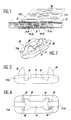
- the junction axis according to the invention is intended to ensure the coupling of two complementary rows of metal junction staples 1a and 1b fixed, by means of cleats 2 made of metal wires, on the ends 3a and 3b of a conveyor belt. More precisely, this junction axis is intended to be threaded into the duct formed by the knuckles 4a and 4b of these staples when the latter are nested one inside the other as shown in FIG. 1.
- the present junction axis is constituted by a series of metallic elements 5 added one after the other around a flexible core 6. Since no role is assigned to it as regards the mechanical resistance of the present axis, this core can be constituted by a twisted metallic cable of very small section, or even by a monofilament wire in synthetic resin or any other suitable material.
- Each of the metal elements attached to this core somehow affects the shape of a solid rod of semi-cylindrical shape (see Figure 2).
- each element 5 has a cavity 9 of similar curved outline, which is intended to receive the ears 8 of another identical element placed above in inverted position with an offset in the axial direction.
- each element somehow affects the shape of a section of gutter.
- the elements thus provided have a short length, for example of the order of 10 to 20 mm for a radius of approximately 3 mm, the flexible core having for its part a diameter of the order of 1 to 2 mm.
- these dimension values are only given as an example.
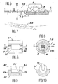
- these elements are arranged on either side of the flexible core 6, in two rows inverted with an offset from one row to another.
- the elements of one of the rows are designated by the reference 5a, while those of the other row are designated by the reference 5b.
- the offset between the two rows is such that each element of a given row is placed partly opposite one of the halves of an element 5 of the other row, and partly opposite one of the halves of another adjacent element 5 of this other row.
- the projecting ears 8 of the elements 5a of the corresponding row are caused to penetrate into the cavities 9 of the facing elements 5b of the other row, and vice versa.
- the dimensions are such that this penetration must be effected by force, which causes the ends of the two ears 8 of each pair to bend towards one another. This ensures the crimping of these ears around the flexible core 6, as shown in FIG. 6.
- the elements 5a and 5b have a certain freedom of movement with respect to each other in all directions, other than the axial direction.
- these elements can slightly struggle with respect to the diametral plane X-Y of superposition of the two rows.
- they can also struggle slightly with respect to the axial plane perpendicular thereto.
- they can also carry out any other complex movement of travel. This possibility of movement of the elements 5 relative to each other therefore ensures the desired flexibility of the axis thus formed so that the corresponding conveyor belt can curve in the shape of a trough on the rollers which serve as supports.
- the particular shape of the protruding lugs 8 for attachment and of the cavities 9 for receiving them facilitates the movement of movement of the elements 5a and 5b relative to each other.
- the ears 8 can be articulated in all directions inside the cavities 9.
- this junction axis does not raise any particular problem since it suffices to ensure the assembly of the two opposing rows of elements 5a and 5b on either side of the flexible core 6 while respecting the desired offset. .
- the present junction pin has a high mechanical resistance enabling it to effectively resist the wear caused by the repeated friction of the knuckles 4a and 4b of the junction clips. corresponding 1a and 1b. Consequently, the possible duration of use of this axis is much longer than that of the axes currently used for coupling junction staples.
- this axis it is possible to remove it very easily, even if it has been broken at an intermediate point of its length. Indeed, as all the elements 5a and 5b are hung one after the other, it is possible to extract all of these by pulling on the elements located at the ends of the axis, even if the flexible core 6 no longer exists.
- the attachment of the elements 5 one after the other also has the important advantage that during the period of use of this junction axis, there cannot be a separation of two successive elements under the effect of the pressure exerted by the knuckles 4a and 4b of the junction clips, and consequently a deterioration of the present axis.
- this axis is manufactured by stamping, which allows realize the particular shapes provided in these figures for the ears 8 and the cavities 9.
- these elements could also be made of cut and folded sheet metal.
- the projecting ears 8c of each of the corresponding elements 5c would be located at the very ends of this element above a terminal flange 11.
- the dimensions of the different parts are such that this assembly by force causes the crimping of the ends of the ears 8c around the flexible core 6 of corresponding junction.
- junction axis As already indicated, this is intended to be used for the coupling of two complementary rows of junction staples previously attached to the ends of a conveyor belt or the like.
- this joint axis Due to its very high mechanical resistance, this joint axis has a duration much longer than the axes used so far for the same application. In addition, it is capable of being used, without disadvantage, in very abrasive media.
Landscapes
- Engineering & Computer Science (AREA)
- General Engineering & Computer Science (AREA)
- Mechanical Engineering (AREA)
- Belt Conveyors (AREA)
- Chain Conveyers (AREA)
Applications Claiming Priority (2)
| Application Number | Priority Date | Filing Date | Title |
|---|---|---|---|
| FR8717618 | 1987-12-17 | ||
| FR8717618A FR2624940A1 (fr) | 1987-12-17 | 1987-12-17 | Axe de jonction pour l'accouplement des extremites d'un tapis transporteur ou similaire |
Publications (2)
| Publication Number | Publication Date |
|---|---|
| EP0324290A1 true EP0324290A1 (de) | 1989-07-19 |
| EP0324290B1 EP0324290B1 (de) | 1991-01-30 |
Family
ID=9357965
Family Applications (1)
| Application Number | Title | Priority Date | Filing Date |
|---|---|---|---|
| EP88403013A Expired - Lifetime EP0324290B1 (de) | 1987-12-17 | 1988-11-30 | Kupplungsstab zum Verbinden der Enden eines Transportbandes oder dgl. |
Country Status (12)
| Country | Link |
|---|---|
| US (1) | US4858280A (de) |
| EP (1) | EP0324290B1 (de) |
| JP (1) | JPH01197214A (de) |
| CN (1) | CN1016886B (de) |
| BR (1) | BR8806665A (de) |
| CS (1) | CS274634B2 (de) |
| DE (1) | DE3861722D1 (de) |
| ES (1) | ES2021155B3 (de) |
| FR (1) | FR2624940A1 (de) |
| PL (1) | PL276495A1 (de) |
| SU (1) | SU1750438A3 (de) |
| ZA (1) | ZA889417B (de) |
Cited By (1)
| Publication number | Priority date | Publication date | Assignee | Title |
|---|---|---|---|---|
| EP0738840A2 (de) * | 1995-04-20 | 1996-10-23 | Goro S.A. | Riemenverbinder |
Families Citing this family (7)
| Publication number | Priority date | Publication date | Assignee | Title |
|---|---|---|---|---|
| DE68910694T2 (de) * | 1989-12-14 | 1994-05-05 | Goro Sa | Dichtung für die Verbindung von zwei Stücken eines Förderbandes und eine solche Dichtung aufweisende Verbindung. |
| FR2701300B1 (fr) * | 1993-02-09 | 1995-03-31 | Aser Sarl | Dispositif de jonctionnement pour bande transporteuse. |
| USD423749S (en) * | 1998-09-14 | 2000-04-25 | Flexible Steel Lacing Company | Conveyor belt fastener |
| FR2921141B1 (fr) * | 2007-09-19 | 2010-03-12 | Aser Sarl | Dispositif perfectionne de jonction pour bandes transportables |
| USD808253S1 (en) | 2014-08-18 | 2018-01-23 | Flexible Steel Lacing Company | Fastener for a conveyor belt |
| RU2707434C2 (ru) * | 2014-08-18 | 2019-11-26 | Флексибл Стил Лейсинг Компани | Соединитель конвейерных лент и способ его изготовления |
| FR3025576B1 (fr) * | 2014-09-04 | 2017-04-21 | Aser Sarl | Dispositif de jonction pour bande transporteuse |
Citations (7)
| Publication number | Priority date | Publication date | Assignee | Title |
|---|---|---|---|---|
| FR720857A (fr) * | 1930-11-05 | 1932-02-25 | Supplex Ets | Perfectionnements aux baguettes charnières utilisées comme chevilles axiales dans la liaison des extrémités d'un ou de plusieurs éléments formant attaches de courroies |
| DE926645C (de) * | 1952-06-19 | 1955-04-21 | Hugo Timmerbeil Fa | Riemenverbinder |
| US2962782A (en) * | 1957-12-09 | 1960-12-06 | Flexible Steel Lacing Co | Hinge pin |
| FR2196683A5 (de) * | 1972-08-14 | 1974-03-15 | Matthaei Mato Masch | |
| FR2301738A1 (fr) * | 1975-02-21 | 1976-09-17 | Matthaei Mato Masch | Barre de jonction pour reunir les extremites de bandes transporteuses |
| FR2574510A1 (fr) * | 1984-12-11 | 1986-06-13 | Goro Sa | Dispositif destine a assurer la liaison articulee de deux series complementaires d'agrafes de jonction |
| US4597137A (en) * | 1984-09-12 | 1986-07-01 | Ocenco Incorporated | Hinge pin and hinge pin tool |
Family Cites Families (5)
| Publication number | Priority date | Publication date | Assignee | Title |
|---|---|---|---|---|
| GB162157A (en) * | 1920-03-15 | 1921-04-28 | Tage Georg Nyborg | Improvements relating to belt-fasteners |
| US1607108A (en) * | 1926-07-10 | 1926-11-16 | Arther G Whitehead | Belt coupling |
| US1975862A (en) * | 1933-04-26 | 1934-10-09 | Flexible Steel Lacing Co | Hinged fastening |
| US2145455A (en) * | 1937-10-05 | 1939-01-31 | Flexible Steel Lacing Co | Flexible belt fastener |
| US2256155A (en) * | 1938-06-22 | 1941-09-16 | Wingfoot Corp | Belt fastener |
-
1987
- 1987-12-17 FR FR8717618A patent/FR2624940A1/fr active Pending
-
1988
- 1988-11-30 DE DE8888403013T patent/DE3861722D1/de not_active Expired - Fee Related
- 1988-11-30 US US07/277,849 patent/US4858280A/en not_active Expired - Fee Related
- 1988-11-30 ES ES88403013T patent/ES2021155B3/es not_active Expired - Lifetime
- 1988-11-30 EP EP88403013A patent/EP0324290B1/de not_active Expired - Lifetime
- 1988-12-15 ZA ZA889417A patent/ZA889417B/xx unknown
- 1988-12-16 CN CN88108613A patent/CN1016886B/zh not_active Expired
- 1988-12-16 SU SU884613001A patent/SU1750438A3/ru active
- 1988-12-16 BR BR888806665A patent/BR8806665A/pt unknown
- 1988-12-16 CS CS837488A patent/CS274634B2/cs unknown
- 1988-12-17 PL PL27649588A patent/PL276495A1/xx unknown
- 1988-12-17 JP JP63319350A patent/JPH01197214A/ja active Pending
Patent Citations (7)
| Publication number | Priority date | Publication date | Assignee | Title |
|---|---|---|---|---|
| FR720857A (fr) * | 1930-11-05 | 1932-02-25 | Supplex Ets | Perfectionnements aux baguettes charnières utilisées comme chevilles axiales dans la liaison des extrémités d'un ou de plusieurs éléments formant attaches de courroies |
| DE926645C (de) * | 1952-06-19 | 1955-04-21 | Hugo Timmerbeil Fa | Riemenverbinder |
| US2962782A (en) * | 1957-12-09 | 1960-12-06 | Flexible Steel Lacing Co | Hinge pin |
| FR2196683A5 (de) * | 1972-08-14 | 1974-03-15 | Matthaei Mato Masch | |
| FR2301738A1 (fr) * | 1975-02-21 | 1976-09-17 | Matthaei Mato Masch | Barre de jonction pour reunir les extremites de bandes transporteuses |
| US4597137A (en) * | 1984-09-12 | 1986-07-01 | Ocenco Incorporated | Hinge pin and hinge pin tool |
| FR2574510A1 (fr) * | 1984-12-11 | 1986-06-13 | Goro Sa | Dispositif destine a assurer la liaison articulee de deux series complementaires d'agrafes de jonction |
Cited By (2)
| Publication number | Priority date | Publication date | Assignee | Title |
|---|---|---|---|---|
| EP0738840A2 (de) * | 1995-04-20 | 1996-10-23 | Goro S.A. | Riemenverbinder |
| EP0738840A3 (de) * | 1995-04-20 | 1996-11-20 | Goro S.A. | Riemenverbinder |
Also Published As
| Publication number | Publication date |
|---|---|
| AU597517B2 (en) | 1990-05-31 |
| CS274634B2 (en) | 1991-09-15 |
| PL276495A1 (en) | 1989-07-10 |
| CN1034045A (zh) | 1989-07-19 |
| AU2696888A (en) | 1989-06-22 |
| FR2624940A1 (fr) | 1989-06-23 |
| ZA889417B (en) | 1989-09-27 |
| CS837488A2 (en) | 1991-03-12 |
| EP0324290B1 (de) | 1991-01-30 |
| JPH01197214A (ja) | 1989-08-08 |
| ES2021155B3 (es) | 1991-10-16 |
| CN1016886B (zh) | 1992-06-03 |
| DE3861722D1 (de) | 1991-03-07 |
| SU1750438A3 (ru) | 1992-07-23 |
| US4858280A (en) | 1989-08-22 |
| BR8806665A (pt) | 1989-08-29 |
Similar Documents
| Publication | Publication Date | Title |
|---|---|---|
| EP0852132B1 (de) | Blutfilter mit verbesserter Durchlässigkeit | |
| FR2569337A1 (fr) | Construction d'une fixation liberable utilisable notamment dans le domaine des bijoux personnels | |
| EP0582493A1 (de) | Gefäss-Filter mit dreieckigen Schenkeln | |
| FR2484220A1 (fr) | Boucles pour bracelets tels que bracelets de montres | |
| FR2685015A1 (fr) | Attache rapide pour la liaison d'au moins un element funiculaire par rapport a l'extremite d'un cordon. | |
| EP0324290B1 (de) | Kupplungsstab zum Verbinden der Enden eines Transportbandes oder dgl. | |
| EP0166645A1 (de) | Biegsame Achse zur beweglichen Verbindung von hakenartigen Transportriemenschlössern | |
| FR2473136A1 (fr) | Collier de fixation notamment de cables electriques | |
| EP1498384A1 (de) | Karabinerhaken mit zwei gegenüberliegenden Enden | |
| FR2465114A1 (fr) | Sandow muni de crochets, ainsi que procede et outil pour la fabrication d'un tel sandow | |
| EP3165108A1 (de) | Kinnriemenverbinder mit variablem bruch | |
| EP0661938B1 (de) | Faltverschluss für armbänder | |
| EP1646297A1 (de) | Bandförmiges verbindungsteil, insbesondere uhrarmband, das durch abschneiden gekürzt werden kann | |
| EP0187061B1 (de) | Vorrichtung zu einer gelenkigen Verbindung von zwei ergänzenden Reihen von Verbindungshaken | |
| FR2622415A1 (fr) | Bijou a elements constitutifs interchangeables | |
| EP0636567B1 (de) | Zusammenklappbare Kabeltrommel | |
| FR2619292A1 (fr) | Fermoir pour bracelet | |
| EP0289490B1 (de) | Karabinerhaken für bergsteiger, höhlenforscher und ähnliche personen | |
| EP0315722A1 (de) | Verschluss | |
| EP0437639B1 (de) | Dichtung für die Verbindung von zwei Stücken eines Förderbandes und eine solche Dichtung aufweisende Verbindung | |
| EP0550623A1 (de) | Vorrichtung und verfahren zum anbringen eines taues um einen festmacherpfosten | |
| FR2708800A1 (fr) | Ensemble de suspension de câbles électriques. | |
| CH667194A5 (fr) | Fermoir de type invisible pour bracelet, notamment pour bracelet-montre. | |
| EP1046354A1 (de) | Haarspange | |
| FR2870690A1 (fr) | Bijou transformable |
Legal Events
| Date | Code | Title | Description |
|---|---|---|---|
| PUAI | Public reference made under article 153(3) epc to a published international application that has entered the european phase |
Free format text: ORIGINAL CODE: 0009012 |
|
| AK | Designated contracting states |
Kind code of ref document: A1 Designated state(s): DE ES GB |
|
| 17P | Request for examination filed |
Effective date: 19900102 |
|
| 17Q | First examination report despatched |
Effective date: 19900511 |
|
| GRAA | (expected) grant |
Free format text: ORIGINAL CODE: 0009210 |
|
| AK | Designated contracting states |
Kind code of ref document: B1 Designated state(s): DE ES GB |
|
| GBT | Gb: translation of ep patent filed (gb section 77(6)(a)/1977) | ||
| REF | Corresponds to: |
Ref document number: 3861722 Country of ref document: DE Date of ref document: 19910307 |
|
| PLBE | No opposition filed within time limit |
Free format text: ORIGINAL CODE: 0009261 |
|
| STAA | Information on the status of an ep patent application or granted ep patent |
Free format text: STATUS: NO OPPOSITION FILED WITHIN TIME LIMIT |
|
| PG25 | Lapsed in a contracting state [announced via postgrant information from national office to epo] |
Ref country code: ES Free format text: LAPSE BECAUSE OF EXPIRATION OF PROTECTION Effective date: 19911202 |
|
| PGFP | Annual fee paid to national office [announced via postgrant information from national office to epo] |
Ref country code: DE Payment date: 19920117 Year of fee payment: 4 |
|
| 26N | No opposition filed | ||
| PG25 | Lapsed in a contracting state [announced via postgrant information from national office to epo] |
Ref country code: GB Effective date: 19921130 |
|
| GBPC | Gb: european patent ceased through non-payment of renewal fee |
Effective date: 19921130 |
|
| PG25 | Lapsed in a contracting state [announced via postgrant information from national office to epo] |
Ref country code: DE Effective date: 19930803 |
|
| REG | Reference to a national code |
Ref country code: ES Ref legal event code: FD2A Effective date: 20010201 |