EP0324183A1 - One piece support with several levels for the thermal treatment of shafts or axles - Google Patents
One piece support with several levels for the thermal treatment of shafts or axles Download PDFInfo
- Publication number
- EP0324183A1 EP0324183A1 EP88121890A EP88121890A EP0324183A1 EP 0324183 A1 EP0324183 A1 EP 0324183A1 EP 88121890 A EP88121890 A EP 88121890A EP 88121890 A EP88121890 A EP 88121890A EP 0324183 A1 EP0324183 A1 EP 0324183A1
- Authority
- EP
- European Patent Office
- Prior art keywords
- parts
- orifices
- ribs
- support
- shafts
- Prior art date
- Legal status (The legal status is an assumption and is not a legal conclusion. Google has not performed a legal analysis and makes no representation as to the accuracy of the status listed.)
- Granted
Links
Images


Classifications
-
- C—CHEMISTRY; METALLURGY
- C21—METALLURGY OF IRON
- C21D—MODIFYING THE PHYSICAL STRUCTURE OF FERROUS METALS; GENERAL DEVICES FOR HEAT TREATMENT OF FERROUS OR NON-FERROUS METALS OR ALLOYS; MAKING METAL MALLEABLE, e.g. BY DECARBURISATION OR TEMPERING
- C21D9/00—Heat treatment, e.g. annealing, hardening, quenching or tempering, adapted for particular articles; Furnaces therefor
- C21D9/0006—Details, accessories not peculiar to any of the following furnaces
- C21D9/0025—Supports; Baskets; Containers; Covers
-
- F—MECHANICAL ENGINEERING; LIGHTING; HEATING; WEAPONS; BLASTING
- F27—FURNACES; KILNS; OVENS; RETORTS
- F27D—DETAILS OR ACCESSORIES OF FURNACES, KILNS, OVENS, OR RETORTS, IN SO FAR AS THEY ARE OF KINDS OCCURRING IN MORE THAN ONE KIND OF FURNACE
- F27D5/00—Supports, screens, or the like for the charge within the furnace
- F27D5/005—Supports specially adapted for holding elongated articles in an upright position, e.g. sparking plugs
Abstract
Description
L'invention concerne les montages de support et de manutention pour le traitement thermique en groupes de pièces mécaniques telles que des arbres ou des axes.The invention relates to support and handling assemblies for heat treatment in groups of mechanical parts such as shafts or axes.
Les montages de traitements thermiques les plus couramment utilisés sont de deux types : un premier type où les pièces sont posées et guidées, et un deuxième type où les pièces sont suspendues.The most commonly used heat treatment assemblies are of two types: a first type where the parts are placed and guided, and a second type where the parts are suspended.
Les montages du premier type sont constitués par un plateau de base pour la manutention comportant des colonnes sur lesquelles se montent une grille inférieure et une grille supérieure séparées par des entretoises tubulaires entourant les colonnes, chaque pièce étant supportée par un intercalaire de support se montant dans un des logements de la grille inférieure, et guidée à sa partie supérieure par un intercalaire de guidage se montant dans un orifice similaire de la grille supérieure.The assemblies of the first type consist of a base plate for handling comprising columns on which are mounted a lower grid and an upper grid separated by tubular spacers surrounding the columns, each part being supported by a support interlayer being mounted in one of the housings of the lower grid, and guided at its upper part by a guide insert being mounted in a similar orifice of the upper grid.
Les montages du deuxième type comportent les mêmes éléments que ceux du premier type, excepté la grille inférieure et les intercalaires de guidage, les intercalaires de support étant d'un type spécial et montés dans la grille supérieure.The second type assemblies include the same elements as those of the first type, except the lower grid and the guide spacers, the support spacers being of a special type and mounted in the upper grid.
Les inconvénients majeurs de ces montages de l'un et l'autre type sont la multiplicité des composants, le poids élevé du montage rapporté au poids des pièces traitées, et corrélativement la grande inertie thermique, la complexité des manipulations de mise en place des pièces conduisant à l'impossibilité pratique de chargement et de déchargement automatiques, et enfin le maintien imparfait des pièces conduisant à des chocs entre pièces préjudiciables à la qualité.The major drawbacks of these assemblies of one and the other type are the multiplicity of the components, the high weight of the assembly in relation to the weight of the parts treated, and correlatively the great thermal inertia, the complexity of the manipulations for placing the parts. leading to the practical impossibility of automatic loading and unloading, and finally the imperfect maintenance of the parts leading to shocks between parts detrimental to the quality.
Le but de l'invention est d'éliminer les inconvénients précédents, c'est-à-dire de réaliser un montage qui, comme les précédents, assure le positionnement vertical des pièces pour éviter les déformations en cours de traitement, mais qui soit tout à la fois le plus léger possible tout en groupant le maximum de nombre de pièces afin de maximiser la charge utile ainsi que le nombre de pièces à traiter par charge, qui favorise les conditions de refroidissement lors de la trempe par un bon passage des fluides, qui soit hautement résistant aux chocs thermiques et aux efforts de poussée d'un four poussant, et qui enfin, permette la mise en place des pièces d'une manière simple aisément automatisable.The object of the invention is to eliminate the above drawbacks, that is to say to produce an assembly which, like the previous ones, ensures the vertical positioning of the parts to avoid deformations during processing, but which is entirely at the same time as light as possible while grouping the maximum number of parts in order to maximize the payload as well as the number of parts to be treated per load, which favors the cooling conditions during quenching by good passage of fluids, which is highly resistant to thermal shock and to the thrust forces of a pushing furnace, and which finally allows the positioning of the parts in a simple manner that can easily be automated.
Pour cela, l'invention consiste à réaliser un montage pour le traitement thermique d'arbres ou d'axes en position verticale comportant un ensemble monobloc en forme de plateau qui réunit à la fois un étage supérieur formé d'orifices de support, éventuellement sur plusieurs niveaux alternés, pour le support et le centrage direct de l'extrémité inférieure des pièces, ces orifices étant réunis par des nervures horizontales, un étage inférieur formé également d'orifices et de nervures, et des piliers verticaux réunissant ces nervures de l'un et l'autre étage, tout en laissant subsister de larges ouvertures pour la circulation des fluides.For this, the invention consists in making an assembly for the heat treatment of trees or axes in a vertical position comprising a monobloc assembly in the form of a plate which combines both an upper stage formed of support orifices, possibly on several alternating levels, for direct support and centering of the lower end of the parts, these orifices being joined by horizontal ribs, a lower stage also formed of orifices and ribs, and vertical pillars joining these ribs from one and the other stage, while leaving large openings for the circulation of fluids .
Eventuellement, plusieurs de ces plateaux garnis de pièces peuvent être superposés au moyen de colonnes étagées.Optionally, several of these trays filled with parts can be superimposed by means of stepped columns.
D'autres particularités de l'invention apparaîtront dans la description qui va suivre de deux modes de réalisation pris comme exemple et représentés sur le dessin annexé, sur lequel :
- la figure 1 est une vue en perspective avec arraché partiel d'un premier mode de réalisation avec une seule des pièces à traiter en place;
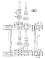
- la figure 2 représente en élévation et en coupe partielle le deuxième mode de réalisation;
- la figure 3 représente en coupe et à plus grande échelle un fragment de ce deuxième mode de réalisation; et
- la figure 4 est une vue de dessus de la figure 3.
- Figure 1 is a perspective view with partial cutaway of a first embodiment with only one of the parts to be treated in place;
- Figure 2 shows in elevation and in partial section the second embodiment;
- Figure 3 shows in section and on a larger scale a fragment of this second embodiment; and
- FIG. 4 is a top view of FIG. 3.
Dans les exemples choisis, les pièces 1 à traiter sont supposées être des arbres 2 de boîte de vitesse comportant plusieurs pignons 3 constitués en une seule pièce avec l'arbre 2, ce type de pièce étant particulièrement difficile à traiter. Bien entendu, l'invention s'appliquerait à fortiori à des pièces longilignes de forme plus simple et moins encombrante.In the examples chosen, the parts 1 to be treated are assumed to be
On voit, sur la figure 1, l'ensemble unique 4 en forme de plateau à deux étages 5 et 6. L'étage supérieur 5 comprend un certain nombre d'orifices 7 entourés chacun par un manchon tubulaire 8, ces divers manchons 8 et orifices 7 étant disposés en réseau bidimentionnel et réunis entre eux par des nervures 9 dans au moins deux directions. Chaque orifice 7 est destiné à recevoir une partie inférieure cylindrique 10 d'une des pièces 1 qui s'appuie par une partie conique ou plane sur le bord supérieur du manchon 8 correspondant.We see, in Figure 1, the single assembly 4 in the form of a two-
L'étage inférieur 6 est constitué également d'orifices 11 entourés par des manchons cylindriques 12 eux-mêmes réunis par des nervures 13, de préférence également dans les deux directions. Des nervures particulières d'encadrement 9a ceinturent tout l'ensemble de l'étage supérieur 5, et de la même manière des nervures particulières 13a ceinturent l'ensemble de l'étage inférieur 6.The
De plus, une série de piliers verticaux 14 réunissent deux à deux des nervures telles que 9 ou 9a de l'étage supérieur et des nervures telles que 13 ou 13a de l'étage inférieur. Enfin, comme il apparaît clairement sur la figure 1, toutes ces nervures et ces piliers laissent subsister entre eux de larges ouvertures 15 servant tout à la fois à assurer la libre circulation du fluide de chauffage, puis de refroidissement, et en même temps à alléger la pièce tout en lui conservant une haute résistance.In addition, a series of
Conformément à l'invention, tout l'ensemble du plateau 4 est réalisé en une seule pièce, ce qui peut être obtenu aisément par exemple en fonderie à l'aide d'un alliage à haute résistance aux chocs thermiques.According to the invention, the whole of the plate 4 is made in one piece, which can be easily obtained for example in foundry using an alloy with high resistance to thermal shock.
Dans le deuxième mode de réalisation des figures 2 à 4, les orifices 7 et les manchons 8 du plateau supérieur sont disposés sur deux niveaux alternés, tels que 8a et 8b, afin d'éviter, comme on le voit sur les figures 2 et 3, l'interférence entre les engrenages 3 de plus grand diamètre afin de réduire l'entraxe des orifices 7 et par suite, augmenter la charge par plateau.In the second embodiment of Figures 2 to 4, the
Dans les deux cas, on a donc un plateau à deux étages sous la forme monobloc, donc très rigide et se déformant de manière uniforme pendant le traitement thermique. En outre, l'ensemble est relativement simple et léger, surtout eu égard au poids de pièces supportées, tout en améliorant la qualité des pièces par une excellente tenue qui empêche les chocs des pièces entre elles pendant le traitement et au cours du chargement.In both cases, there is therefore a two-stage plate in the monobloc form, therefore very rigid and deforming uniformly during the heat treatment. In addition, the assembly is relatively simple and light, especially with regard to the weight of supported parts, while improving the quality of the parts by an excellent resistance which prevents the shocks of the parts between them during treatment and during loading.
Par ailleurs, le chargement des pièces se fait d'une manière extrêmement simple, puisqu'il suffit d'amener chaque pièce en face de l'orifice 7 correspondant et de l'y introduire par simple translation axiale verticale, ce qui est aisément réalisable par un bras manipulateur. Enfin, en plus du faible coût, de la haute résistance, et du faible poids du plateau selon l'invention, le poids de pièces supportées peut être relativement élevé, surtout avec le deuxième mode de réalisation.Furthermore, the loading of the parts is done in an extremely simple manner, since it suffices to bring each part in front of the
Par ailleurs, l'invention permet, si on le désire, de superposer deux ou plusieurs plateaux semblables pour un traitement thermique simultané, en empilant ces plateaux, une fois chargés de leurs pièces, les uns sur les autres au moyen de colonnes étagées telles que représentées en 16 sur la figure2, chacune de ces colonnes ayant par exemple une section en X avec un embout inférieur 17 cylindrique à embase 18 et un embout supérieur 19 qui peut être également à section en X et comporter une embase de butée 20. Les embouts 17 et 19 peuvent se monter dans des trous supplémentaires prévus à cet effet, par exemple dans les angles de chaque plateau 4. Cette dernière disposition améliore encore la densité du chargement, donc la productivité du traitement.Furthermore, the invention makes it possible, if desired, to superimpose two or more similar trays for simultaneous heat treatment, by stacking these trays, once loaded with their parts, on top of each other by means of stepped columns such as shown at 16 in FIG. 2, each of these columns having for example an X section with a cylindrical
Claims (3)
Priority Applications (1)
| Application Number | Priority Date | Filing Date | Title |
|---|---|---|---|
| AT88121890T ATE87089T1 (en) | 1988-01-15 | 1988-12-30 | MULTI-STAGE ONE-PIECE HEAT TREATMENT FITTING FOR SHAFTS AND AXLES. |
Applications Claiming Priority (2)
| Application Number | Priority Date | Filing Date | Title |
|---|---|---|---|
| FR8800451A FR2626068B1 (en) | 1988-01-15 | 1988-01-15 | MONOBLOCK MOUNTING WITH STAGE PLATES FOR THERMAL TREATMENT OF TREES OR AXES |
| FR8800451 | 1988-01-15 |
Publications (2)
| Publication Number | Publication Date |
|---|---|
| EP0324183A1 true EP0324183A1 (en) | 1989-07-19 |
| EP0324183B1 EP0324183B1 (en) | 1993-03-17 |
Family
ID=9362362
Family Applications (1)
| Application Number | Title | Priority Date | Filing Date |
|---|---|---|---|
| EP88121890A Expired - Lifetime EP0324183B1 (en) | 1988-01-15 | 1988-12-30 | One piece support with several levels for the thermal treatment of shafts or axles |
Country Status (9)
| Country | Link |
|---|---|
| US (1) | US4978109A (en) |
| EP (1) | EP0324183B1 (en) |
| JP (1) | JPH01287219A (en) |
| AT (1) | ATE87089T1 (en) |
| CA (1) | CA1327815C (en) |
| DE (1) | DE3879454T2 (en) |
| ES (1) | ES2038737T3 (en) |
| FR (1) | FR2626068B1 (en) |
| PT (1) | PT89429B (en) |
Cited By (3)
| Publication number | Priority date | Publication date | Assignee | Title |
|---|---|---|---|---|
| FR2772467A1 (en) * | 1997-12-15 | 1999-06-18 | Snecma | LOADING DEVICE FOR SUPPORTING PARTS TO BE HEAT TREATED IN AN OVEN |
| CN102483306A (en) * | 2009-08-14 | 2012-05-30 | Gtd石墨技术股份有限公司 | Improved workpiece-carrier |
| CN105349740A (en) * | 2015-11-15 | 2016-02-24 | 岳文智 | Quenching support for metal tube machining |
Families Citing this family (14)
| Publication number | Priority date | Publication date | Assignee | Title |
|---|---|---|---|---|
| DE4016172C1 (en) * | 1990-05-19 | 1991-03-28 | Werner 5900 Siegen De Ackermann | |
| DE29608569U1 (en) * | 1996-05-13 | 1996-08-14 | Heess Karl Maschinen | Device for receiving and implementing heat treatment steps to be subjected to workpieces |
| US5752821A (en) * | 1996-07-02 | 1998-05-19 | Kia Motors Corporation | Tray for heat treatment furnace |
| DE19957906A1 (en) * | 1999-12-01 | 2001-06-28 | Schunk Kohlenstofftechnik Gmbh | Method for producing a fiber composite component and device for producing one |
| DE10109565B4 (en) * | 2001-02-28 | 2005-10-20 | Vacuheat Gmbh | Method and device for partial thermochemical vacuum treatment of metallic workpieces |
| WO2002097141A1 (en) | 2001-05-29 | 2002-12-05 | Demmer Corporation | Heat treatment container |
| CN1322148C (en) * | 2004-12-16 | 2007-06-20 | 上海汽车股份有限公司 | Quenching for material rack by high pressure gas |
| DE102005001440A1 (en) * | 2005-01-09 | 2006-07-20 | Wolfgang Meinus | Device for mounting of workpieces installed in vertical position, such as shafts and axles for thermal treatment, has multi-tier unit with supports cast on grate and centered between grates by conical and/or pyramid connections |
| CN102080144B (en) * | 2010-11-29 | 2012-08-08 | 苏州中门子科技有限公司 | Module type deformation-resisting furnace baseboard |
| KR101366704B1 (en) | 2012-06-22 | 2014-02-25 | (주)수산서비스 | A basket for heat treatmenting of breaker parts |
| JP6697902B2 (en) * | 2016-02-26 | 2020-05-27 | 株式会社三井ハイテック | Tray and heat treatment method |
| WO2020040207A1 (en) * | 2018-08-21 | 2020-02-27 | 日光金属株式会社 | Tray member for heat treatment and laminated structure for heat treatment |
| CN109366394A (en) * | 2018-12-05 | 2019-02-22 | 盐城远大金属科技有限公司 | A kind of band hole axle class tooling |
| CN112359197A (en) * | 2020-11-10 | 2021-02-12 | 中冶陕压重工设备有限公司 | Tray for large heat treatment gas furnace |
Citations (3)
| Publication number | Priority date | Publication date | Assignee | Title |
|---|---|---|---|---|
| GB190904370A (en) * | 1909-02-22 | 1909-10-07 | Frank Dransfield | An Improved Device for use in the Manufacture of Earthenware Pipes and the like. |
| DE2542083B1 (en) * | 1975-07-30 | 1976-03-25 | Deere & Co | Transport container made of heat-resistant steel for articles to be hardened |
| US4572749A (en) * | 1984-03-07 | 1986-02-25 | Gkn Automotive Components, Inc. | Method and an apparatus for heat treatment of a workpiece |
Family Cites Families (9)
| Publication number | Priority date | Publication date | Assignee | Title |
|---|---|---|---|---|
| US2179073A (en) * | 1935-06-10 | 1939-11-07 | Timken Axle Co Detroit | Apparatus for heat treating |
| US2137737A (en) * | 1937-04-13 | 1938-11-22 | Albert W Wenzel | Packing ring holding apparatus |
| US2300783A (en) * | 1940-11-16 | 1942-11-03 | Wright Aeronautical Corp | Furnace charging fixture |
| US2369756A (en) * | 1941-12-20 | 1945-02-20 | American Steel & Wire Co | Base for metallurgical furnaces and the like |
| SU389154A1 (en) * | 1971-04-05 | 1973-07-05 | ||
| JPS5078332A (en) * | 1973-11-08 | 1975-06-26 | ||
| US4212690A (en) * | 1979-03-23 | 1980-07-15 | Nasa | Heat treat fixture and method of heat treating |
| JPS636194U (en) * | 1986-07-01 | 1988-01-16 | ||
| US4815971A (en) * | 1987-11-27 | 1989-03-28 | Westinghouse Electric Corp. | Multi-tier load fixture for a top-loading furnace furnace |
-
1988
- 1988-01-15 FR FR8800451A patent/FR2626068B1/en not_active Expired - Lifetime
- 1988-12-15 US US07/284,549 patent/US4978109A/en not_active Expired - Fee Related
- 1988-12-30 DE DE8888121890T patent/DE3879454T2/en not_active Expired - Fee Related
- 1988-12-30 EP EP88121890A patent/EP0324183B1/en not_active Expired - Lifetime
- 1988-12-30 ES ES198888121890T patent/ES2038737T3/en not_active Expired - Lifetime
- 1988-12-30 AT AT88121890T patent/ATE87089T1/en active
-
1989
- 1989-01-11 CA CA000587967A patent/CA1327815C/en not_active Expired - Fee Related
- 1989-01-12 PT PT89429A patent/PT89429B/en not_active IP Right Cessation
- 1989-01-13 JP JP1007539A patent/JPH01287219A/en active Pending
Patent Citations (3)
| Publication number | Priority date | Publication date | Assignee | Title |
|---|---|---|---|---|
| GB190904370A (en) * | 1909-02-22 | 1909-10-07 | Frank Dransfield | An Improved Device for use in the Manufacture of Earthenware Pipes and the like. |
| DE2542083B1 (en) * | 1975-07-30 | 1976-03-25 | Deere & Co | Transport container made of heat-resistant steel for articles to be hardened |
| US4572749A (en) * | 1984-03-07 | 1986-02-25 | Gkn Automotive Components, Inc. | Method and an apparatus for heat treatment of a workpiece |
Cited By (5)
| Publication number | Priority date | Publication date | Assignee | Title |
|---|---|---|---|---|
| FR2772467A1 (en) * | 1997-12-15 | 1999-06-18 | Snecma | LOADING DEVICE FOR SUPPORTING PARTS TO BE HEAT TREATED IN AN OVEN |
| WO1999031284A1 (en) * | 1997-12-15 | 1999-06-24 | Societe Nationale D'etude Et De Construction De Moteurs D'aviation - Snecma | Loading device for supporting parts to be thermally treated in a furnace |
| US6318571B1 (en) | 1997-12-15 | 2001-11-20 | Societe Nationale D'etude Et De Construction De Moteurs D'aviation - S.N.E.C.M.A. | Loader device for supporting parts for heat treatment in a furnace |
| CN102483306A (en) * | 2009-08-14 | 2012-05-30 | Gtd石墨技术股份有限公司 | Improved workpiece-carrier |
| CN105349740A (en) * | 2015-11-15 | 2016-02-24 | 岳文智 | Quenching support for metal tube machining |
Also Published As
| Publication number | Publication date |
|---|---|
| DE3879454D1 (en) | 1993-04-22 |
| JPH01287219A (en) | 1989-11-17 |
| DE3879454T2 (en) | 1993-09-09 |
| EP0324183B1 (en) | 1993-03-17 |
| CA1327815C (en) | 1994-03-15 |
| PT89429A (en) | 1989-10-04 |
| PT89429B (en) | 1994-01-31 |
| US4978109A (en) | 1990-12-18 |
| FR2626068A1 (en) | 1989-07-21 |
| FR2626068B1 (en) | 1990-06-29 |
| ES2038737T3 (en) | 1993-08-01 |
| ATE87089T1 (en) | 1993-04-15 |
Similar Documents
| Publication | Publication Date | Title |
|---|---|---|
| EP0324183B1 (en) | One piece support with several levels for the thermal treatment of shafts or axles | |
| EP1817776B1 (en) | Installation for welding frameworks of nuclear fuel assemblies, programming method, coresponding methods for framework welding and assembling | |
| EP0468870B1 (en) | Nuclear reactor fuel assembly with additional grid | |
| EP0612869B1 (en) | Waferbasket for silicon wafers | |
| EP1042517B1 (en) | Loading device for supporting parts to be thermally treated in a furnace | |
| EP0858079B1 (en) | Storage rack for nuclear fuel assemblies with neutron absorbing members being held in position by frames | |
| EP0109889B1 (en) | Process and appliance for welding nuclear fuel assembly grids | |
| FR2633436A1 (en) | METHOD AND HOLDING ELEMENT FOR THE REPAIR OF A NUCLEAR COMBUSTIBLE ASSEMBLY, DAMAGED IN PERIPHERY OF A SPACER SUPPORT | |
| EP0477097A1 (en) | Guiding device for the control-rod cluster of a nuclear reactor | |
| FR2647944A1 (en) | FUEL ASSEMBLY OF A NUCLEAR REACTOR COMPRISING A DEVICE FOR RETAINING PARTICLES CONTAINED IN THE REACTOR COOLING FLUID | |
| EP0693593A1 (en) | Method for assembling very long parts of sheet metal girders for the legs of an oilplatform | |
| EP0878009A1 (en) | Nuclear fuel assembly with an upper cap | |
| FR2760474A1 (en) | METHOD FOR ASSEMBLING SECTIONS OF SUPPORT LEGS OF AN OIL PLATFORM | |
| FR2680909A1 (en) | Rack for storage or for transport of nuclear fuel and its method of manufacture | |
| FR2674465A1 (en) | PROCESS FOR WELDING TWO PARTS, IN PARTICULAR AN ELECTRICAL COMPONENT, AND / OR SEMICONDUCTOR WAFER | |
| FR2742912A1 (en) | CONTROL PANEL FOR NUCLEAR REACTOR, WITH REMOVABLE PENCILS | |
| EP0088363B1 (en) | Apparatus for suspending heat exchanger pipe bundles | |
| EP0349379B1 (en) | Control spider with removable rods for a nuclear fuel assembly | |
| BE897638A (en) | Retaining device tape and method for aqssemblage grill bar nuclear fuel support | |
| FR2759847A1 (en) | OPTO-ELECTRONIC PACKAGE WITH CERAMIC INSERT | |
| EP0323306A1 (en) | Pressurized-water nuclear reactor with a massive shroud | |
| FR2693825A1 (en) | Nuclear fuel assembly with axial guide tubes - whose upper ends attach to a plate axially slidable inside upper sleeve to accommodate tube deformation | |
| EP0276791A1 (en) | Device for the stabilization of the loops of a heat exchanger element consisting of tubes in which a fluid circulates | |
| WO2021078520A1 (en) | Gas quenching cell | |
| FR2543350A1 (en) | Structure and process for storing irradiated fuel elements |
Legal Events
| Date | Code | Title | Description |
|---|---|---|---|
| PUAI | Public reference made under article 153(3) epc to a published international application that has entered the european phase |
Free format text: ORIGINAL CODE: 0009012 |
|
| AK | Designated contracting states |
Kind code of ref document: A1 Designated state(s): AT BE DE ES GB IT NL SE |
|
| 17P | Request for examination filed |
Effective date: 19890725 |
|
| 17Q | First examination report despatched |
Effective date: 19910502 |
|
| ITF | It: translation for a ep patent filed |
Owner name: BARZANO' E ZANARDO MILA |
|
| GRAA | (expected) grant |
Free format text: ORIGINAL CODE: 0009210 |
|
| AK | Designated contracting states |
Kind code of ref document: B1 Designated state(s): AT BE DE ES GB IT NL SE |
|
| REF | Corresponds to: |
Ref document number: 87089 Country of ref document: AT Date of ref document: 19930415 Kind code of ref document: T |
|
| REF | Corresponds to: |
Ref document number: 3879454 Country of ref document: DE Date of ref document: 19930422 |
|
| GBT | Gb: translation of ep patent filed (gb section 77(6)(a)/1977) |
Effective date: 19930331 |
|
| REG | Reference to a national code |
Ref country code: ES Ref legal event code: FG2A Ref document number: 2038737 Country of ref document: ES Kind code of ref document: T3 |
|
| PLBE | No opposition filed within time limit |
Free format text: ORIGINAL CODE: 0009261 |
|
| STAA | Information on the status of an ep patent application or granted ep patent |
Free format text: STATUS: NO OPPOSITION FILED WITHIN TIME LIMIT |
|
| 26N | No opposition filed | ||
| EAL | Se: european patent in force in sweden |
Ref document number: 88121890.3 |
|
| PGFP | Annual fee paid to national office [announced via postgrant information from national office to epo] |
Ref country code: GB Payment date: 19991026 Year of fee payment: 12 |
|
| PGFP | Annual fee paid to national office [announced via postgrant information from national office to epo] |
Ref country code: SE Payment date: 19991108 Year of fee payment: 12 |
|
| PGFP | Annual fee paid to national office [announced via postgrant information from national office to epo] |
Ref country code: ES Payment date: 19991207 Year of fee payment: 12 |
|
| PGFP | Annual fee paid to national office [announced via postgrant information from national office to epo] |
Ref country code: BE Payment date: 19991215 Year of fee payment: 12 |
|
| PGFP | Annual fee paid to national office [announced via postgrant information from national office to epo] |
Ref country code: AT Payment date: 19991227 Year of fee payment: 12 |
|
| PGFP | Annual fee paid to national office [announced via postgrant information from national office to epo] |
Ref country code: DE Payment date: 19991228 Year of fee payment: 12 |
|
| PGFP | Annual fee paid to national office [announced via postgrant information from national office to epo] |
Ref country code: NL Payment date: 19991231 Year of fee payment: 12 |
|
| PG25 | Lapsed in a contracting state [announced via postgrant information from national office to epo] |
Ref country code: GB Free format text: LAPSE BECAUSE OF NON-PAYMENT OF DUE FEES Effective date: 20001230 Ref country code: AT Free format text: LAPSE BECAUSE OF NON-PAYMENT OF DUE FEES Effective date: 20001230 |
|
| PG25 | Lapsed in a contracting state [announced via postgrant information from national office to epo] |
Ref country code: SE Free format text: LAPSE BECAUSE OF NON-PAYMENT OF DUE FEES Effective date: 20001231 Ref country code: BE Free format text: LAPSE BECAUSE OF NON-PAYMENT OF DUE FEES Effective date: 20001231 |
|
| BERE | Be: lapsed |
Owner name: SOC. MANCELLE DE FONDERIE Effective date: 20001231 |
|
| PG25 | Lapsed in a contracting state [announced via postgrant information from national office to epo] |
Ref country code: NL Free format text: LAPSE BECAUSE OF NON-PAYMENT OF DUE FEES Effective date: 20010701 |
|
| EUG | Se: european patent has lapsed |
Ref document number: 88121890.3 |
|
| GBPC | Gb: european patent ceased through non-payment of renewal fee |
Effective date: 20001230 |
|
| NLV4 | Nl: lapsed or anulled due to non-payment of the annual fee |
Effective date: 20010701 |
|
| PG25 | Lapsed in a contracting state [announced via postgrant information from national office to epo] |
Ref country code: DE Free format text: LAPSE BECAUSE OF NON-PAYMENT OF DUE FEES Effective date: 20011002 |
|
| PG25 | Lapsed in a contracting state [announced via postgrant information from national office to epo] |
Ref country code: ES Free format text: LAPSE BECAUSE OF NON-PAYMENT OF DUE FEES Effective date: 20011231 |
|
| REG | Reference to a national code |
Ref country code: ES Ref legal event code: FD2A Effective date: 20020112 |
|
| PG25 | Lapsed in a contracting state [announced via postgrant information from national office to epo] |
Ref country code: IT Free format text: LAPSE BECAUSE OF NON-PAYMENT OF DUE FEES;WARNING: LAPSES OF ITALIAN PATENTS WITH EFFECTIVE DATE BEFORE 2007 MAY HAVE OCCURRED AT ANY TIME BEFORE 2007. THE CORRECT EFFECTIVE DATE MAY BE DIFFERENT FROM THE ONE RECORDED. Effective date: 20051230 |