EP0323809B1 - Zusammenklappbarer Rahmen für Sofabetten - Google Patents
Zusammenklappbarer Rahmen für Sofabetten Download PDFInfo
- Publication number
- EP0323809B1 EP0323809B1 EP19880830219 EP88830219A EP0323809B1 EP 0323809 B1 EP0323809 B1 EP 0323809B1 EP 19880830219 EP19880830219 EP 19880830219 EP 88830219 A EP88830219 A EP 88830219A EP 0323809 B1 EP0323809 B1 EP 0323809B1
- Authority
- EP
- European Patent Office
- Prior art keywords
- frame
- carrying structure
- framework
- pivoted
- link member
- Prior art date
- Legal status (The legal status is an assumption and is not a legal conclusion. Google has not performed a legal analysis and makes no representation as to the accuracy of the status listed.)
- Expired
Links
Images


Classifications
-
- A—HUMAN NECESSITIES
- A47—FURNITURE; DOMESTIC ARTICLES OR APPLIANCES; COFFEE MILLS; SPICE MILLS; SUCTION CLEANERS IN GENERAL
- A47C—CHAIRS; SOFAS; BEDS
- A47C17/00—Sofas; Couches; Beds
- A47C17/04—Seating furniture, e.g. sofas, couches, settees, or the like, with movable parts changeable to beds; Chair beds
- A47C17/16—Seating furniture changeable to beds by tilting or pivoting the back-rest
- A47C17/161—Seating furniture changeable to beds by tilting or pivoting the back-rest with back-rest made of multiple movable cushions
-
- A—HUMAN NECESSITIES
- A47—FURNITURE; DOMESTIC ARTICLES OR APPLIANCES; COFFEE MILLS; SPICE MILLS; SUCTION CLEANERS IN GENERAL
- A47C—CHAIRS; SOFAS; BEDS
- A47C17/00—Sofas; Couches; Beds
- A47C17/04—Seating furniture, e.g. sofas, couches, settees, or the like, with movable parts changeable to beds; Chair beds
- A47C17/16—Seating furniture changeable to beds by tilting or pivoting the back-rest
- A47C17/165—Seating furniture changeable to beds by tilting or pivoting the back-rest with forward tiltable back-rest, e.g. back cushion
-
- A—HUMAN NECESSITIES
- A47—FURNITURE; DOMESTIC ARTICLES OR APPLIANCES; COFFEE MILLS; SPICE MILLS; SUCTION CLEANERS IN GENERAL
- A47C—CHAIRS; SOFAS; BEDS
- A47C17/00—Sofas; Couches; Beds
- A47C17/04—Seating furniture, e.g. sofas, couches, settees, or the like, with movable parts changeable to beds; Chair beds
- A47C17/16—Seating furniture changeable to beds by tilting or pivoting the back-rest
- A47C17/17—Seating furniture changeable to beds by tilting or pivoting the back-rest with coupled movement of back-rest and seat
-
- A—HUMAN NECESSITIES
- A47—FURNITURE; DOMESTIC ARTICLES OR APPLIANCES; COFFEE MILLS; SPICE MILLS; SUCTION CLEANERS IN GENERAL
- A47C—CHAIRS; SOFAS; BEDS
- A47C17/00—Sofas; Couches; Beds
- A47C17/04—Seating furniture, e.g. sofas, couches, settees, or the like, with movable parts changeable to beds; Chair beds
- A47C17/16—Seating furniture changeable to beds by tilting or pivoting the back-rest
- A47C17/20—Seating furniture changeable to beds by tilting or pivoting the back-rest thereby uncovering one or more auxiliary parts previously hidden
- A47C17/207—Seating furniture changeable to beds by tilting or pivoting the back-rest thereby uncovering one or more auxiliary parts previously hidden with seat cushion consisting of superposed parts, at least one lower part being used to form part of the surface
- A47C17/2076—Seating furniture changeable to beds by tilting or pivoting the back-rest thereby uncovering one or more auxiliary parts previously hidden with seat cushion consisting of superposed parts, at least one lower part being used to form part of the surface by lifting or tilting
-
- A—HUMAN NECESSITIES
- A47—FURNITURE; DOMESTIC ARTICLES OR APPLIANCES; COFFEE MILLS; SPICE MILLS; SUCTION CLEANERS IN GENERAL
- A47C—CHAIRS; SOFAS; BEDS
- A47C17/00—Sofas; Couches; Beds
- A47C17/04—Seating furniture, e.g. sofas, couches, settees, or the like, with movable parts changeable to beds; Chair beds
- A47C17/16—Seating furniture changeable to beds by tilting or pivoting the back-rest
- A47C17/20—Seating furniture changeable to beds by tilting or pivoting the back-rest thereby uncovering one or more auxiliary parts previously hidden
- A47C17/213—Seating furniture changeable to beds by tilting or pivoting the back-rest thereby uncovering one or more auxiliary parts previously hidden the surface, when used for lying down, consisting of one side of the seat frame and the back-rest frame
Definitions
- the present invention relates to a folding framework for sofa-beds and the like, of the type comprising a fixed carrying structure, a first frame having one end connected to the carrying structure, a second frame having one end rotatably hinged to the second end of the first frame and a third frame having one end rotatably hinged to the second end of the second frame, said framework lending itself to be brought from an extended condition in which said first, second and third frames are consecutively aligned, to a collapsed or folded up condition in which said frames are mutually superposed.
- One of these types is substantially comprised of a fixed carrying structure to which three frames are associated which frames are connected to one another by torsion bars forming linkage parallelograms. Frames can be brought from a condition in which they are superposed on one another so that the framework may perform itssolution as a sofa, to a condition in which they are disposed in coplanar relation so that the framework may perform its function as a bedstead. To the framework taken as a whole is then added an element designed to form the sofa padding when the frames are mutually superposed and which can be spread out to form a mattress when the frames are in mutual alignment.
- Sofa-beds provided with the above described frameworks have some drawbacks as regards their comfortableness in use, above all when they have to be utilised as beds.
- said drawbacks are originated from the fact that the lying plane formed by the frames inevitably exhibits two or more stiff crosspieces formed with a portion of the perimeter extension of the single frames.
- frameworks are formed with three frames which can be brought from a spread out condition in which they are horizontally aligned, to a folded up condition in which two of them are book-folded so as to form the sofa back, the other frame forming the sofa seat.
- the drawback of these frameworks is that they give rise to back of great bulkiness when they are used to form a sofa, due to the thickness of the book-folded frames to which the thickness of the stuffed element disposed on either side of the frames themselves has to be added.
- a further object of the present invention is to provide a framework which is practical in use as regards the operations to be carried out to reach either the mutual alignment or folding of the frames.
- a folding framework for sofa-beds and the like characterized in that it comprises, for each of its opposed sides: an attachment bracket fastened to one end of the second frame; a first link member pivoted to one end of said attachment bracket and, on the opposite side, to the carrying structure; a second link member pivoted to the attachment bracket at a location between the second frame and the pivoting point of the first link member and, on the opposite side, to the carrying structure at a location which is raised with respect to the pivoting point of the first link member on the carrying structure; a supporting foot hinged to the second end of the second frame; a first tie rod pivoted to the first end of the third frame and, on the opposite side, to said foot; and a second tie rod pivoted to the foot at a location between the second frame and the pivoting point of the first tie rod and, on the opposite side, to the carrying structure.
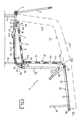
- the framework 1 comprises a fixed carrying structure 2 and a base portion 3 extending to form a rectangle and provided with bearing elements 3a. Fastened to the back of the base portion 3 is a supporting portion 4 extending in a substantially vertical direction and designed to be part of a back 5 when, as shown in Fig. 1, the framework 1 is disposed in its folded condition to be used as a sofa.
- the framework 1 further comprises a first frame 6 consisting of two longitudinal members 7 (only one of which is shown in the accompanying drawings), connected to a crosspiece 8 at one end 6a of the frame itself. Conventional elastic splines or staves 9, known per se, extend between the longitudinal members 7.
- the first frame is connected to the base portion 3 by means of a strut lever 10.
- the strut lever 10 consists of two telescopically engaged portions 10a and 10b which are pivoted to the first frame 6 and the carrying structure 2 respectively.
- a second frame 11 comprised of two longitudinal members 12 extending along the opposed sides of the framework 1 and between which two elastic staves 13 similar to the above mentioned ones 9, are engaged.
- an attachment bracket 14 is fastened to either longitudinal member 12, in the region of end 11a, which bracket allows the second frame 11 to be connected to the carrying structure 2.
- the attachment bracket 14 is connected to the carrying structure 2 by means of a first link member 15 pivoted to the bracket at one end thereof and to the front of the base portion 3 at the opposite end thereof.
- a second link member 16 is provided as well, which, as seen in Fig. 2, rotatably hinged to the attachment bracket 14 at a location between the second frame 11 and the pivoting point of the first link member 15.
- the second link member 16 On the opposite side to that facing the bracket 14 the second link member 16 is rotatably connected to the base portion 3 at a raised location as compared with the pivoting point of the first link member 15 on the base portion itself.
- the second link member 16 is hinged to the upper end of a support 17 standing at the front from the base portion 3.
- a lifting lever 18 is rigidly engaged to each of said longitudinal members 12, close to the first end 11a of the second frame 11, to the free end of said lever being secured a connection cable 19.
- the connection cable 19 is trained around an idler wheel 20 rotatably engaged to the base portion 3 and is connected to one end 21a of a return spring 21 the second end of which 21b is fastened to the carrying structure 2.
- the end 21b should be connected to the base portion 3 through an attachement element 22 which in this embodiment consists of a perforated plate.
- the attachment element 22 is provided with a number of holes 23 distributed such as to be differently spaced from the first end 21a of spring 21 and each of them is adapted to engage the second end 21b of said spring in order to achieve a determined preloading of the latter.
- a third frame 24 is rotatably pivoted, at one end 24a thereof, to the second end of the second frame 11; said thrid frame consists of two longitudinal members 25 that are mutually connected by means of crosspieces 26 engaging them at the respective opposite ends.
- Elastic staves 27 similar to the above mentioned staves 9 and 13 extend between the crosspieces 26 and they are disposed at right angles to the first staves.
- fixed supporting feed 28 are rigidly fastened to one of the crosspieces 26 located close to the free end 24b of the third frame 24.
- the framework 1 in accordance with the invention further comprises two movable supporting feet 29 each of them being hinged to one of the longitudinal members 12 in the second frame 11, adjacent the second end 11b of the latter. Pivoted to each movable foot 29 is one tie rod 30 rotatably connected, on the side opposite that facing the foot, to one of the longitudinal members at one end 24a of the third frame 24.
- a second tie rod 31 is rotatably pivoted to the foot 18 at a location between the pivoting point of the foot itself on the second frame 11 and the pivoting point of the first tie rod 30.
- the second tie rod 31 is hinged to the upper end of the support 17 in coaxial relation with the pivoting of the second link member 16.
- a stuffed element 32 is conventionally associated with framework 1.
- Said stuffed element 32 is shown in dotted line and is designed to form the padding for the sofa when the framework is disposed in its folded up condition, as shown in Fig. 1 and to serve as a mattress when the framework, as shown in Fig. 4, is in its spread out condition to be used as a bedstead.
- the framework 1 when the framework 1 is used as a sofa the three frames 6, 11 and 24 are disposed book-folded upon one another.
- the first frame 6 rests on the base portion 3 of the carrying structure 2 by which it is supported while the second frame 11 is laid upon the first frame 6 and the third frame 24 is laid upon the second frame 11.
- the stability of the relative positioning of frames is ensured by the alignment between the pivoting points of the first tie rod 30 on the third frame 24 and the movable foot 29 and the pivoting point of the second tie rod 31 on said movable foot.
- the stuffed element 32 is folded too, so as to form a first portion 32a and a second portion 32b disposed book-like against the supporting portion 4 to form the back padding 5. Following the second portion 32b there is a third portion 32c extending over the third frame 24 to form the padding for the sofa seat.
- the raising of the third frame 24 causes the overturning of the second frame 11 about the pivoting points of link members 15 and 16 on the attachment bracket 14. Simultaneously with the mutual rotation of frames, due to the action of tie rods 30 and 31 it is possible to achieve the shifting of the movable foot 29 from a rest position, in which the latter is adjacent the second frame 11, to a working condition in which, as shown in Fig. 3, said foot is substantially disposed at right angles to frames 11 and 24 so that it may rest on the floor.
- the engagement offered by link members 15 and 16 is sufficient to allow the second frame 11 to execute, during the alignment and/or folding operations, shiftings adapted to enable the third frame to keep a substantially horizontal orientation, by virtue of the engagement resulting from the presence of tie rods 30 and 31 and foot 29.
- the movements performed by the second frame will cause, during a first step of the frame aligning operation, a slight backward movement of the first frame 6 on the base portion 3.
- the shiftings of the second frame will on the contrary cause the lifting of the second end 6b of the first frame 6 and the forward movement of the latter with respect to the base portion 3.
- portions 10a and 10b of the strut lever 10 will slide with respect to each other to assist the backward movement of the first frame 6.
- the strut lever 10 will turn about its pivoting axis on the base portion 3 to bring the first end 6a flush with the second end 6b so that the first frame 6 at the end of the operation will be in alignment with the two other frames 11, 24.
- the portions 10a and 10b when frames are aligned it will be possible to fix the portions 10a and 10b according to different positions in order to allow the first frame 6 to take the desired inclination.
- the spring 21 is arranged so as to facilitate the initial steps of a subsequent frame folding operation, which is achieved by exerting a lifting action on the crosspiece 26 which is raised from the position shown in Fig. 4 so that the elements of the framework 1 can perform a series of shiftings in a way opposite that described with reference to the alignment operation.
- the present invention attains the intended purposes.
- the framework of the invention can offer a great comfortableness in use when it is in its spread out condition, that is when used as a bed.
- no crosspieces exist between the first end of the first frame 6 and the second end 11b of the second frame 11.
- the crosspiece 26 at the first end 24a of the third frame 24 it does not cause any particular trouble to the user, as it is substantially disposed at the bottom of the bedstead formed with framework 1.
- the framework of the invention is also very practical in use as far as the frame aligning and folding operations are concerned. It is in fact to be noted that, although the development of these operations has been hereinbefore described as carried out in several steps in succession, the alignment and folding of the frames are achieved respectively by a single operation on the part of the user, consisting in lifting the third frame 24 and causing the translation of the same.
Landscapes
- Health & Medical Sciences (AREA)
- General Health & Medical Sciences (AREA)
- Nursing (AREA)
- Special Chairs (AREA)
Claims (5)
- Umbiegbares Gestell (1) für Schlafsofas und dergleichen, enthaltend:- ein ortsfestes Traggerüst (2),- ein erstes Gestell (6) mit einem mit dem Traggerüst (2) verbundenen Ende (6a),- ein zweites Gestell (11) mit einem am zweiten Ende (6a) des ersten Gestelles (6) drehbar angelenkten Ende (11a),- ein drittes Gestell (24) mit einem am zweiten Ende (11b) des zweiten Gestelles (11) drehbar angelenkten Ende (24a),wobei sich das o.e. Gestell (1) dazu eignet, aus einem entfalteten Zustand - in welchem die o.e. erstes, zweites bzw. drittes Gestelle (6, 11, 24) nacheinander ausgerichtet sind - zu einem ein- bzw. umgebogenen Zustand gebracht zu werden, in welchem die o.e. Gestelle übereinander überlappt sind,
dadurch gekennzeichnet, daß es für jede dessen entgegegesetzten Seiten folgendes enthält:- ein am ersten Ende (11a) des zweiten Gestelles (11) befestigtes Kupplungsbügel (14),- eine erste Anlenkslasche (15), die an einem Ende des o.e. Kupplungsbügels (14) und andererseits an dem Traggerüst (2) derhbar gelagert ist,- eine zweite Anlenkslasche (16), die am Kupplungsbügel (14) in einer zwischen dem zweiten Gestell (11) und dem Anlenkpunkt der ersten Anlenklasche (15) befindlichen Lage und andererseits am Traggestell (2) in einer höher als der Anlenkpunkt der ersten Anlenklasche (15) am Traggestell (2) befindlichen Lage drehbar gelagert ist,- einen Stützfuß (29), der am zweiten Ende (11b) des zweiten Gestelles (11) angelenkt ist,- einen ersten Spannstab (30), der am ersten Ende (24a) des dritten Gestelles (24) und andererseits am o.e. Fuß (29) drehbar gelagert ist,- einen zweiten Spannstab (31), der am Stützfuß (29) in einer zwischen dem zweiten Gestell (11) und dem Anlenkpunkt des ersten Spannstabes (30) befindlichen Lage und andererseits am Traggerüst (2) drehbar gelagert ist. - Gestell nach Anspruch 1, dadurch gekennzeichnet, daß es darüber hinaus einen Hubhebel (18) enthält, der am ersten Ende (11a) des zweiten Gestelles (11) befestigt ist, sowie ein am o.e. Hubhebel (18) befestigtes und um eine am Traggerüst gelagerte Umlenkrolle (20) geführtes Verbindungsseil (19) und eine Rückstellfeder (21), deren ein Ende (21a) am Verbindungsseil (19) bei dessen dem Hubhebel (18) entgegengesetzten Ende befestigt ist, während deren anderes Ende (21b) am Traggerüst (2) befestigt ist, wobei sich der o.e. Hubhebel (18) eignet, sich der o.e. Umlenkrolle (20) anzunähern und davon wieder zu entfernen, als das Gestell aus dessen umgebogenen Zustand zum ausgebreiteten Zustand gebracht wird.
- Gestell nach Anspruch 2, dadurch gekennzeichnet, daß das zweite Ende (21b) der o.e. Feder (21) am Traggerüst (2) mittels eines Kupplungsmittels (22) befestigt ist, das am Traggerüst (2) selbst befestigt und mit mehreren Löchern (23) versehen ist, die darüber derart verteilt sind, daß sie sich in verschiedenen Abständen vom ersten Ende (21a) der Feder (21) befinden.
- Gestell nach Anspruch 2, dadurch gekennzeichnet, daß das o.e. Gestell (6) mit dem Traggerüst (2) über wenigstens einen Strebehebel (10) verbunden ist, der zwei teleskopisch ineinandergreifende Teile (10a, 10b) enthält.
- Gestell nach Anspruch 4, dadurch gekennzeichnet, daß bei der ausgebreiteten Lage des Gestelles (1) die o.e. Teile (10a, 10b) nach einer gewünschten Positionierung zueinander starr gefesselt werden können.
Applications Claiming Priority (2)
| Application Number | Priority Date | Filing Date | Title |
|---|---|---|---|
| IT2041188U IT213569Z2 (it) | 1988-01-08 | 1988-01-08 | Intelaiatura pieghevole per divaniletto e simili. |
| IT2041188U | 1988-01-08 |
Publications (2)
| Publication Number | Publication Date |
|---|---|
| EP0323809A1 EP0323809A1 (de) | 1989-07-12 |
| EP0323809B1 true EP0323809B1 (de) | 1992-12-09 |
Family
ID=11166524
Family Applications (1)
| Application Number | Title | Priority Date | Filing Date |
|---|---|---|---|
| EP19880830219 Expired EP0323809B1 (de) | 1988-01-08 | 1988-05-18 | Zusammenklappbarer Rahmen für Sofabetten |
Country Status (3)
| Country | Link |
|---|---|
| EP (1) | EP0323809B1 (de) |
| DE (1) | DE3876610D1 (de) |
| IT (1) | IT213569Z2 (de) |
Families Citing this family (3)
| Publication number | Priority date | Publication date | Assignee | Title |
|---|---|---|---|---|
| ES1011271Y (es) * | 1989-06-20 | 1992-01-01 | Somieres Mecanizados Gaitan, S.A. (Somegasa) | Estructura plegable para sofa convertible. |
| GB2299933A (en) * | 1995-04-22 | 1996-10-23 | Raymond Lester Mawdsley | Convertible chair/bed |
| IT1286917B1 (it) * | 1996-04-17 | 1998-07-17 | Lampolet Spa | Divano letto |
Family Cites Families (2)
| Publication number | Priority date | Publication date | Assignee | Title |
|---|---|---|---|---|
| US3813710A (en) * | 1972-10-12 | 1974-06-04 | Hoover Ball & Bearing Co | Foldable bed bottom frame assembly for use in sofa beds and the like |
| DE3701058A1 (de) * | 1987-01-13 | 1988-07-21 | Wolfgang Dipl Ing Zimmermann | Klappsofa |
-
1988
- 1988-01-08 IT IT2041188U patent/IT213569Z2/it active
- 1988-05-18 EP EP19880830219 patent/EP0323809B1/de not_active Expired
- 1988-05-18 DE DE88830219T patent/DE3876610D1/de not_active Expired - Lifetime
Also Published As
| Publication number | Publication date |
|---|---|
| IT8820411V0 (it) | 1988-01-08 |
| IT213569Z2 (it) | 1990-01-22 |
| EP0323809A1 (de) | 1989-07-12 |
| DE3876610D1 (en) | 1993-01-21 |
Similar Documents
| Publication | Publication Date | Title |
|---|---|---|
| US4402096A (en) | Folding bed chair with detachable cushions | |
| US2595038A (en) | Sofa bed | |
| US4538308A (en) | Convertible furniture | |
| US2007988A (en) | Davenport bed | |
| GB2213371A (en) | Sofa-bed | |
| US4922561A (en) | Convertible sofa-bed | |
| US3432203A (en) | Bed-sofa | |
| US3771178A (en) | Removable linkage for a foldable bed | |
| US3209378A (en) | Convertible article of furniture | |
| US5913770A (en) | Folding sofa-bed frame | |
| US4800598A (en) | Anti-tilt sofa sleeper mechanism | |
| US4051564A (en) | Portable convertible sofa-bunk beds | |
| EP0323809A1 (de) | Zusammenklappbarer Rahmen für Sofabetten | |
| US5075909A (en) | Anti-tilt sofa sleeper mechanism | |
| US3085257A (en) | Convertible ottoman bed | |
| US3024473A (en) | Convertible article of furniture | |
| US2584145A (en) | Foldable sofa bed | |
| US5097544A (en) | Convertible sofa bed | |
| KR20000065072A (ko) | 팬터그라프지지대제어기구 | |
| US3508283A (en) | Sofa bed | |
| US4590630A (en) | Tri-fold mechanism | |
| US2803019A (en) | Davenport bed | |
| WO1987004056A1 (en) | Mechanism for a sofa sleeper | |
| US3096528A (en) | Couch convertible into beds | |
| US3187351A (en) | Sofa convertible into a bed by unfolding in one direction only |
Legal Events
| Date | Code | Title | Description |
|---|---|---|---|
| PUAI | Public reference made under article 153(3) epc to a published international application that has entered the european phase |
Free format text: ORIGINAL CODE: 0009012 |
|
| AK | Designated contracting states |
Kind code of ref document: A1 Designated state(s): BE DE ES FR |
|
| 17P | Request for examination filed |
Effective date: 19891227 |
|
| 17Q | First examination report despatched |
Effective date: 19920416 |
|
| GRAA | (expected) grant |
Free format text: ORIGINAL CODE: 0009210 |
|
| AK | Designated contracting states |
Kind code of ref document: B1 Designated state(s): BE DE ES FR |
|
| PG25 | Lapsed in a contracting state [announced via postgrant information from national office to epo] |
Ref country code: FR Effective date: 19921209 Ref country code: ES Free format text: THE PATENT HAS BEEN ANNULLED BY A DECISION OF A NATIONAL AUTHORITY Effective date: 19921209 Ref country code: DE Effective date: 19921209 Ref country code: BE Effective date: 19921209 |
|
| REF | Corresponds to: |
Ref document number: 3876610 Country of ref document: DE Date of ref document: 19930121 |
|
| EN | Fr: translation not filed | ||
| PLBE | No opposition filed within time limit |
Free format text: ORIGINAL CODE: 0009261 |
|
| STAA | Information on the status of an ep patent application or granted ep patent |
Free format text: STATUS: NO OPPOSITION FILED WITHIN TIME LIMIT |
|
| 26N | No opposition filed |