EP0323391A2 - Sich selbsteinstellender Bergsteiger-Klemmkeil - Google Patents
Sich selbsteinstellender Bergsteiger-Klemmkeil Download PDFInfo
- Publication number
- EP0323391A2 EP0323391A2 EP88630237A EP88630237A EP0323391A2 EP 0323391 A2 EP0323391 A2 EP 0323391A2 EP 88630237 A EP88630237 A EP 88630237A EP 88630237 A EP88630237 A EP 88630237A EP 0323391 A2 EP0323391 A2 EP 0323391A2
- Authority
- EP
- European Patent Office
- Prior art keywords
- wedge element
- translating
- chock
- depression
- fixed
- Prior art date
- Legal status (The legal status is an assumption and is not a legal conclusion. Google has not performed a legal analysis and makes no representation as to the accuracy of the status listed.)
- Withdrawn
Links
- 230000009194 climbing Effects 0.000 title claims abstract description 40
- 230000006835 compression Effects 0.000 claims abstract description 12
- 238000007906 compression Methods 0.000 claims abstract description 12
- 230000000295 complement effect Effects 0.000 claims abstract description 8
- 230000000694 effects Effects 0.000 claims description 5
- 230000008878 coupling Effects 0.000 claims 3
- 238000010168 coupling process Methods 0.000 claims 3
- 238000005859 coupling reaction Methods 0.000 claims 3
- 230000001788 irregular Effects 0.000 abstract description 6
- 238000003780 insertion Methods 0.000 abstract description 5
- 230000037431 insertion Effects 0.000 abstract description 5
- 230000009471 action Effects 0.000 description 6
- 230000000875 corresponding effect Effects 0.000 description 5
- 241001503987 Clematis vitalba Species 0.000 description 3
- 230000006872 improvement Effects 0.000 description 2
- 238000004519 manufacturing process Methods 0.000 description 2
- 238000000034 method Methods 0.000 description 2
- 239000011435 rock Substances 0.000 description 2
- 238000005219 brazing Methods 0.000 description 1
- 230000002079 cooperative effect Effects 0.000 description 1
- 230000009977 dual effect Effects 0.000 description 1
- 239000000463 material Substances 0.000 description 1
- 238000012986 modification Methods 0.000 description 1
- 230000004048 modification Effects 0.000 description 1
- 230000008520 organization Effects 0.000 description 1
Images

Classifications
-
- A—HUMAN NECESSITIES
- A63—SPORTS; GAMES; AMUSEMENTS
- A63B—APPARATUS FOR PHYSICAL TRAINING, GYMNASTICS, SWIMMING, CLIMBING, OR FENCING; BALL GAMES; TRAINING EQUIPMENT
- A63B29/00—Apparatus for mountaineering
- A63B29/02—Mountain guy-ropes or accessories, e.g. avalanche ropes; Means for indicating the location of accidentally buried, e.g. snow-buried, persons
- A63B29/024—Climbing chocks
-
- Y—GENERAL TAGGING OF NEW TECHNOLOGICAL DEVELOPMENTS; GENERAL TAGGING OF CROSS-SECTIONAL TECHNOLOGIES SPANNING OVER SEVERAL SECTIONS OF THE IPC; TECHNICAL SUBJECTS COVERED BY FORMER USPC CROSS-REFERENCE ART COLLECTIONS [XRACs] AND DIGESTS
- Y10—TECHNICAL SUBJECTS COVERED BY FORMER USPC
- Y10S—TECHNICAL SUBJECTS COVERED BY FORMER USPC CROSS-REFERENCE ART COLLECTIONS [XRACs] AND DIGESTS
- Y10S248/00—Supports
- Y10S248/925—Mountain climbing aids, e.g. pitons etc.
Definitions
- This invention relates to the art of mountain and rock climbing equipment and, more particularly, to a self-adjusting climbing chock for temporary insertion into a crevice to provide a secure anchor point.
- chocks A certain class of such implements are generally termed "chocks".
- a chock is provided with a loop at one end and a crevice-engaging structure at the other end in order that it can be slipped into a crevice and wedged in place to effect the anchor point.
- chocks may be have no moving parts, and the crevice-engaging end may simply be a wedge shaped piece to which a loop structure is attached.
- more sophisticated chocks have come into use which employ complementary sliding wedges with a moving wedge element which may be drawn against a spring bias toward the climber for insertion into the crevice and then released to, in effect, increase the thickness of the effective wedge.
- Similar, more complex, chocks employ a cam action to obtain corresponding operation.
- Typical of the prior art chocks are those disclosed in United States Patents 3,903,785 to Pepper, Jr.; 3,957,237 to Campbell; 4,082,241 to Burkey; 4,572,464 to Phillips; and 4,643,738 to Guthrie et al.
- a self adjusting climbing chock including a main cable structure having a looped end and first and second cable end sections.
- a fixed wedge element is joined to the cable end sections toward the edges of the wedge.
- a depression is provided which tapers from the inner end and outwardly diverges toward the outer end.
- a translating wedge element having a bearing surface which is complementary to the sliding surface of the depression, may be manually retracted against a compression spring between a first position at which the combined thickness of the fixed and translating wedge elements exceeds the maximum thickness of the fixed wedge element and a second position in which the combined thickness does not exceed the maximum thickness of the fixed wedge element.
- the adjustable climbing chock may be inserted into a crevice simultaneously with finger actuation of a transverse pull component to configure the wedge end of the chock into the insertion position such that subsequent release of the transverse pull component results in the spring returning the translating wedge element to a position between the first and second positions which is variable according to the thickness of the crevice at that point. Any tension placed on the looped end then simply more firmly anchors the chock.
- one preferred embodiment of the invention employs a spherical section translating wedge element cooperating with a depression configured as an inside cylindrical section.
- a "universal-joint" action is obtained as the wedge end components of the climbing chock automatically adjust to the irregular surface within a crevice which it is engaging.
- Embodiments employing a plurality of translating wedge elements in conjunction with a corresponding plurality of depressions on different faces of a single fixed wedge element are also contemplated.
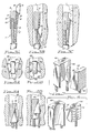
- Fig. 1 there is shown a pictorial illustration of the embodiment of the invention which is presently particularly preferred because of its simplicity, strength and effectiveness.
- the basic structure of the climbing chock may best be understood by simultaneous reference to Figs. 1, 2A and 3A.
- the climbing chock 1 is configured around a main cable structure having a looped region 2 at its lower end and first and second cable end sections 3, 4 which are adjoined, respectively, to a fixed wedge element 5.
- the cable end sections 3, 4 join the fixed wedge element 5 near the outboard edges 6, 7 of its inner end 8.
- one method for securely adjoining the cable end sections 3, 4 to the fixed wedge element 5 is by providing blind holes in the inner end 8 to receive short lengths of the cable end sections such that the end sections may be bonded into place as by brazing or other appropriate means of sufficient strength given the application of the chock.
- the holes to which the cable end sections 3, 4 pass for adjoining to the fixed wedge element 5 are preferably placed, respectively, near the side edges 6, 7 to obtain balance and give strength to the entire structure.
- the fixed wedge element 5 has upper and lower faces 12, 13, and in the embodiment of the chock under present discussion, a single depression 14 is provided in the upper face 12.
- the depression 14 tapers from the inner end 8 of the fixed wedge element toward the outer end 9 and is oriented such that the least thickness between the upper and lower faces 12, 13 is at the inner end 8 of the wedge element 5 and grows progressively greater toward the outer end 9.
- a translating wedge element 15 is adapted to reside with a bearing surface within the depression 14, and a manually actuable system is provided for pulling the translating wedge element 15 between a first position (as shown in Fig. 3A) at which the combined thickness of the fixed wedge element 5 and the translating wedge element 15 exceeds the maximum thickness of the fixed wedge element 5 and a second position (see Figs. 1 and 3B) at which the combined thickness of the fixed wedge element 5 and the translating wedge element 15 does not exceed the maximum thickness of the fixed wedge element 5. That is, the translating wedge element 15 has a bearing surface complementary to the contour of the engaged region of the depression 14 when the bearing surface is in contact with the depression. Thus, the taper of the depression 14 in coordination with the fore and aft movement of the translating wedge 15 governs the effective combined thickness of the structure.
- the manually actuable retraction system includes a retracting cable 17 having a first end 18 connected to the translating wedge element 15 and a second end 19 fixed to a transverse movable, finger-actuable transverse pull component 20 situated intermediate the fixed wedge element 5 and the looped end 2 of the main cable structure.
- first and second intermediate cable sections 21, 22 of the main cable structure are disposed, respectively, between the first cable end section 3 and the second cable end section 4.
- the intermediate cable sections are juxtaposed side by side and pass through respective apertures 23, 24 through the transverse pull component 20 to effect a guide structure for the transverse pull component.
- a compression spring 25 serves as a biasing element normally urging the translating wedge element 15 along the depression 14 away from the looped region 2; i.e., to the position shown in Figs. 2A and 3A.
- the intermediate cable section 22 passes axially through the compression spring which bears at one end against the outer surface of the transverse pull component 20 and, at the other end, against a shoulder 26 of a sheath 27 which serves to maintain the definition of the looped region 2 of the main cable structure.
- the shoulder 26 serves as a lower stop for the compression spring 25.
- Fig. 3A the chock 1 is shown in its relaxed position in which the translating wedge element 15 is in its outboard-most position.
- the climber pulls the translating wedge element 15 into its innermost position by actuating the transverse pull component 20 against the compression spring 25 simultaneously inserting the chock 1 into a crevice 30 as indicated by the arrow 31 in Fig. 3B.
- the pull piece 20 is released, and the assembly is allowed to assume the position illustrated in Fig. 3C under the influence of the compression spring 25.
- the translating wedge element 15 tends to move upwardly in the depression 14 in the direction indicated by the arrow 32 while the fixed wedge element 5 tends to move downwardly as indicated by the arrow 33, this cooperative action securely wedging the entire structure in the crevice 30 such that any tensile force applied to withdraw the assembly from the crevice 30 will simply further tighten it into place.
- Withdrawal of the chock 1 from the crevice 30 may be readily effected by simply pulling the transverse pull component 20 against the compression spring again to release the assembly such that it may be withdrawn in the direction opposite to that indicated by the arrow 31 in Fig. 3B.
- a plurality of translating wedge elements may be employed in conjunction with a plurality of depressions provided on a corresponding plurality of faces of a single fixed wedge element to obtain variant configurations of the chock.
- a climbing chock 40 which includes a pair of translating wedge elements 41 movable within depressions 42 situated on opposite faces of a fixed wedge element 43.
- the fore and aft movement of the translating wedge elements 41 is carried out in synchronism by employing a pair of retracting cables 44 which are both connected to transverse pull component 45 in the manner previously described.
- the chock 40 is used in the same manner previously described for the chock 1 in conjunction with Figs. 3A, 3B and 3C. That is, as shown in Fig. 5B, the chock 40 is inserted into the crevice 46 with the translating wedge elements 41 in a retracted position to permit entry, and then, as shown in Fig. 5C, the translating wedge elements 41 are emplaced by releasing the transverse pull piece 45 (Fig. 4) permitting the wedge assembly to adjust itself to the width of the crevice 46 and anchor the chock 40 until it is subsequently removed as previously described for the chock 1.
- the broken away region 39 illustrates that the translating wedge element may be coupled securely to the retracting cable 44 in much the manner previously described four adjoining the cable end sections 3, 4 to the fixed wedge element 5.
- the translating wedge element is a spherical section (such as a hemisphere) having an outer face and oriented with a spherical portion of its surface nesting in the depression in which it resides during fore and aft movement in the depression.
- This configuration achieves a very effective self adjusting action somewhat in the nature of a "universal-joint".
- the depressions 14, 42 is an inside cylindrical section dimensioned such that the engaging bearing surfaces of the translating wedge elements and the depressions are complementary; i.e., the spherical section of a given translating wedge element has about the same radius as the cylindrical section surface of the depression in which it resides.
- Figs. 6A and 6B are top views of a dual translating wedge chock 40 inserted, respectively, into irregular crevices 47 and 48; i.e., crevices in which the opposing faces 49, 50 and 51, 52 respectively, are not parallel.
- the translating wedge elements 41 inherently pivot as may be necessary (and in three axes) for the outer faces 53 to engage the crevice walls to the maximum extent. It will be appreciated and understood that the single translating wedge element 15 of the embodiment of the invention illustrated in Figs.
- 1, 2A, 2B, 3A, 3B and 3C will function in a fully "universal-joint" equivalent action with the lower face 13 of the fixed wedge element accommodating itself to one crevice wall and the outer face 16 of the translating wedge element 15 accommodating itself to the other crevice wall.
- FIGs. 7, 8A, 8B and 9 other complementary engaging surfaces for the translating wedge element and the fixed wedge element may be employed.
- a generally planar-floored depression 60 of the fixed wedge element 61 engages the complementary surface 62 of a translating wedge element 63.
- the outer surface 64 of the translating wedge element 63 may be knurled or otherwise patterned to increase its gripping characteristics.
- a corresponding surface may be employed on the outboard surface (out of view in Fig. 7) of the fixed wedge element 61. In practice, it has been found that any improvement in gripping function obtained by such pattern treatment is incremental and is usually not necessary.
- Figs. 8A and 8B illustrate, respectively, the insertion and engagement of a chock employing the fixed wedge element 61 and the translating wedge element 63 in a crevice 65. It will be noted that the "universal-joint" action obtained by the use of spherical section translating wedge elements and cylindrical section depressions is not obtained in this embodiment of the invention although a very strong structure is realized.
- the fixed wedge element 66 has a generally cylindrical section depression 67 for receiving the correspondingly generally cylindrical outer bearing surface 69 of translating wedge element 68.
- the translating wedge element 68 may undergo circumferential adjustment to accommodate corresponding irregularities in facing crevice walls by pivoting about the axis of the cylinder of which the surface 69 is a section.
- the outer face 70 of the translating wedge element 68 illustrates yet another optional finish which, for certain conditions, may improve the gripping power of the chock.
Landscapes
- Health & Medical Sciences (AREA)
- Pulmonology (AREA)
- General Health & Medical Sciences (AREA)
- Physical Education & Sports Medicine (AREA)
- Clamps And Clips (AREA)
- Bridges Or Land Bridges (AREA)
Applications Claiming Priority (2)
| Application Number | Priority Date | Filing Date | Title |
|---|---|---|---|
| US07/137,737 US4834327A (en) | 1987-12-24 | 1987-12-24 | Self-adjusting climbing chock |
| US137737 | 1987-12-24 |
Publications (2)
| Publication Number | Publication Date |
|---|---|
| EP0323391A2 true EP0323391A2 (de) | 1989-07-05 |
| EP0323391A3 EP0323391A3 (en) | 1989-12-27 |
Family
ID=22478842
Family Applications (1)
| Application Number | Title | Priority Date | Filing Date |
|---|---|---|---|
| EP88630237A Withdrawn EP0323391A3 (en) | 1987-12-24 | 1988-12-20 | Self adjusting climbing chock |
Country Status (4)
| Country | Link |
|---|---|
| US (1) | US4834327A (de) |
| EP (1) | EP0323391A3 (de) |
| DE (1) | DE323391T1 (de) |
| ES (1) | ES2011208A4 (de) |
Cited By (4)
| Publication number | Priority date | Publication date | Assignee | Title |
|---|---|---|---|---|
| FR2698668A1 (fr) * | 1992-12-02 | 1994-06-03 | Elgiabu Ramadan | Dispositif destiné à relier rapidement un système d'élévation mobile à un support fixe ou les deux parties d'un remorquage ou d'un amarrage. |
| US6493922B2 (en) * | 2000-05-09 | 2002-12-17 | Metolius Mountain Products, Inc. | Climbing nut |
| EP1653830A4 (de) * | 2003-07-28 | 2007-09-12 | Eric W Reeves | Dehnbarer lochanker mit vergrössertem bremsfreigebenden schlagkopf |
| WO2013173216A3 (en) * | 2012-05-14 | 2014-02-27 | Climb Tech, Llc | Concrete anchor point system |
Families Citing this family (23)
| Publication number | Priority date | Publication date | Assignee | Title |
|---|---|---|---|---|
| US5484132A (en) * | 1995-02-08 | 1996-01-16 | George; Philip B. | Removable piton climbing aid and method of using |
| CA2184863C (en) * | 1996-09-05 | 2003-01-21 | Douglas Kashuba | Collapsible snow probe |
| US6119993A (en) * | 1996-12-18 | 2000-09-19 | Youngblood; Gary S. | Climbing anchors |
| US6109578A (en) * | 1998-08-10 | 2000-08-29 | Guthrie; Karl | Borehole-engaging apparatus |
| US6092773A (en) * | 1999-03-05 | 2000-07-25 | Kieliszewski; Randal A. | Retrievable cylindrical wedged anchor |
| US6283426B1 (en) | 2000-02-04 | 2001-09-04 | Karl Guthrie | Spring-loaded camming nut |
| US7011281B2 (en) * | 2002-02-28 | 2006-03-14 | Karl Guthrie | Expansion bolt |
| US6729821B2 (en) | 2002-02-28 | 2004-05-04 | Karl Guthrie | Expansion bolt |
| US6991201B1 (en) * | 2003-08-27 | 2006-01-31 | Bellsouth Intellectual Property Corporation | Line support systems |
| US6971615B1 (en) * | 2003-08-27 | 2005-12-06 | Bellsouth Intellectual Property Corp. | Line support systems |
| US7357363B2 (en) * | 2003-12-30 | 2008-04-15 | Karl Guthrie | Expansion bolt |
| US7275726B2 (en) * | 2004-01-22 | 2007-10-02 | Black Diamond Equipment, Ltd. | Active camming device surface |
| US7278618B2 (en) * | 2004-01-22 | 2007-10-09 | Black Diamond Equipment, Ltd. | Active camming device |
| US20070257171A1 (en) * | 2004-07-27 | 2007-11-08 | Sigma Industries, Llc | Pivot handle for use with expansible hole anchor |
| US7258316B2 (en) * | 2004-07-27 | 2007-08-21 | Reeves Eric W | Expansible hole anchor with enlarged chock-releasing striker head |
| US7127781B2 (en) * | 2004-09-20 | 2006-10-31 | Neil Pryde Limited | Release device for a kite |
| US20070194193A1 (en) * | 2006-02-23 | 2007-08-23 | Klingler Gregory L | Interlocking Climbing Chock |
| US20090056267A1 (en) * | 2007-07-12 | 2009-03-05 | Reeves Eric William | Expansible hole anchor |
| US8353653B2 (en) * | 2009-10-09 | 2013-01-15 | Karl Guthrie | Anchor bolt providing for fall protection |
| US20130340217A1 (en) * | 2012-06-22 | 2013-12-26 | Abraham Madrigal | Firefighter/rescue worker utility anchor |
| US9163651B2 (en) | 2013-03-14 | 2015-10-20 | Meyer Ostrobrod | Concrete anchor |
| CN113309789B (zh) * | 2021-06-09 | 2022-05-31 | 深圳市佐本科技有限公司 | 一种高速轴座用加强散热机构 |
| GB2617355A (en) * | 2022-04-05 | 2023-10-11 | Safehold Ltd | An anchor |
Family Cites Families (8)
| Publication number | Priority date | Publication date | Assignee | Title |
|---|---|---|---|---|
| US3478641A (en) * | 1967-02-07 | 1969-11-18 | Dohmeier Hans Otto | Anchor or roof bolts and the like |
| DE3174914D1 (en) * | 1980-09-03 | 1986-08-14 | Salewa Gmbh Sportgeraetefab | Anchoring device for mountain climbers |
| US4506924A (en) * | 1982-09-30 | 1985-03-26 | Nieder Charles E | Rock lifting device |
| US4572464A (en) * | 1983-10-17 | 1986-02-25 | Phillips Douglas D | Change-configuration climbing chock |
| SE441568B (sv) * | 1984-03-12 | 1985-10-21 | Curt Svensson | Forankringsanordning avsedd for bergsklettring |
| US4643378A (en) * | 1985-03-18 | 1987-02-17 | Karl Guthrie | Roller-chock climbing aid |
| US4715568A (en) * | 1985-09-20 | 1987-12-29 | David A. Hornbeck | Expansible piton |
| GB8615164D0 (en) * | 1986-06-20 | 1986-07-23 | Ryden D | Climbing aid |
-
1987
- 1987-12-24 US US07/137,737 patent/US4834327A/en not_active Expired - Fee Related
-
1988
- 1988-12-20 ES ES88630237T patent/ES2011208A4/es active Pending
- 1988-12-20 DE DE198888630237T patent/DE323391T1/de active Pending
- 1988-12-20 EP EP88630237A patent/EP0323391A3/en not_active Withdrawn
Cited By (5)
| Publication number | Priority date | Publication date | Assignee | Title |
|---|---|---|---|---|
| FR2698668A1 (fr) * | 1992-12-02 | 1994-06-03 | Elgiabu Ramadan | Dispositif destiné à relier rapidement un système d'élévation mobile à un support fixe ou les deux parties d'un remorquage ou d'un amarrage. |
| US6493922B2 (en) * | 2000-05-09 | 2002-12-17 | Metolius Mountain Products, Inc. | Climbing nut |
| EP1653830A4 (de) * | 2003-07-28 | 2007-09-12 | Eric W Reeves | Dehnbarer lochanker mit vergrössertem bremsfreigebenden schlagkopf |
| WO2013173216A3 (en) * | 2012-05-14 | 2014-02-27 | Climb Tech, Llc | Concrete anchor point system |
| US8839591B2 (en) | 2012-05-14 | 2014-09-23 | Climb Tech, Llc | Concrete anchor point system |
Also Published As
| Publication number | Publication date |
|---|---|
| DE323391T1 (de) | 1989-12-07 |
| ES2011208A4 (es) | 1990-01-01 |
| US4834327A (en) | 1989-05-30 |
| EP0323391A3 (en) | 1989-12-27 |
Similar Documents
| Publication | Publication Date | Title |
|---|---|---|
| US4834327A (en) | Self-adjusting climbing chock | |
| US4832289A (en) | Anchoring device for use in crevices | |
| US4643377A (en) | Mechanically expanding climbing aid | |
| US5015023A (en) | Automatic cable gripping device | |
| US6109578A (en) | Borehole-engaging apparatus | |
| GB1588317A (en) | Climbing aids | |
| US6283426B1 (en) | Spring-loaded camming nut | |
| US4572464A (en) | Change-configuration climbing chock | |
| US12129880B2 (en) | Expansion bolt and pivot and swivel mechanism therefor | |
| US3903785A (en) | Rock climbing anchor | |
| US20080262503A1 (en) | Surgical Tool and Method | |
| US3139163A (en) | Ground anchor | |
| AU616414B2 (en) | Apparatus for detachably clamping, tensioning and securing ropes, cables, wires, belts or the like | |
| US20020162927A1 (en) | Camming devices | |
| US6375139B1 (en) | Anchoring device for use in rock crevices and the like during rock climbing activities | |
| US20030005557A1 (en) | Bundling device | |
| US5234074A (en) | Lanyard with pole gripping means | |
| US20030006351A1 (en) | Anchoring device for use in rock crevices and the like during rock climbing activities | |
| US4234151A (en) | Self-locking adjustable support devices | |
| US6092773A (en) | Retrievable cylindrical wedged anchor | |
| EP0047232B1 (de) | Klemmvorrichtung zum Klettern | |
| CA1171642A (en) | Cable connector | |
| US12274331B2 (en) | Securement and release device for webbing | |
| US4765574A (en) | Mountain climbing safety device | |
| US5119529A (en) | Cable hook |
Legal Events
| Date | Code | Title | Description |
|---|---|---|---|
| PUAI | Public reference made under article 153(3) epc to a published international application that has entered the european phase |
Free format text: ORIGINAL CODE: 0009012 |
|
| AK | Designated contracting states |
Kind code of ref document: A2 Designated state(s): AT BE CH DE ES FR GB LI LU NL SE |
|
| TCNL | Nl: translation of patent claims filed | ||
| PUAL | Search report despatched |
Free format text: ORIGINAL CODE: 0009013 |
|
| TCAT | At: translation of patent claims filed | ||
| EL | Fr: translation of claims filed | ||
| DET | De: translation of patent claims | ||
| AK | Designated contracting states |
Kind code of ref document: A3 Designated state(s): AT BE CH DE ES FR GB LI LU NL SE |
|
| 17P | Request for examination filed |
Effective date: 19900626 |
|
| 17Q | First examination report despatched |
Effective date: 19910122 |
|
| STAA | Information on the status of an ep patent application or granted ep patent |
Free format text: STATUS: THE APPLICATION IS DEEMED TO BE WITHDRAWN |
|
| 18D | Application deemed to be withdrawn |
Effective date: 19910604 |