EP0323091A2 - Apparatus for a rebounding ball game - Google Patents
Apparatus for a rebounding ball game Download PDFInfo
- Publication number
- EP0323091A2 EP0323091A2 EP88311976A EP88311976A EP0323091A2 EP 0323091 A2 EP0323091 A2 EP 0323091A2 EP 88311976 A EP88311976 A EP 88311976A EP 88311976 A EP88311976 A EP 88311976A EP 0323091 A2 EP0323091 A2 EP 0323091A2
- Authority
- EP
- European Patent Office
- Prior art keywords
- court
- deflecting element
- rebound surface
- peripheral edge
- generally
- Prior art date
- Legal status (The legal status is an assumption and is not a legal conclusion. Google has not performed a legal analysis and makes no representation as to the accuracy of the status listed.)
- Withdrawn
Links
Images


Classifications
-
- A—HUMAN NECESSITIES
- A63—SPORTS; GAMES; AMUSEMENTS
- A63B—APPARATUS FOR PHYSICAL TRAINING, GYMNASTICS, SWIMMING, CLIMBING, OR FENCING; BALL GAMES; TRAINING EQUIPMENT
- A63B67/00—Sporting games or accessories therefor, not provided for in groups A63B1/00 - A63B65/00
- A63B67/002—Games using balls, not otherwise provided for
-
- A—HUMAN NECESSITIES
- A63—SPORTS; GAMES; AMUSEMENTS
- A63B—APPARATUS FOR PHYSICAL TRAINING, GYMNASTICS, SWIMMING, CLIMBING, OR FENCING; BALL GAMES; TRAINING EQUIPMENT
- A63B67/00—Sporting games or accessories therefor, not provided for in groups A63B1/00 - A63B65/00
- A63B67/04—Table games physically beneficial for the human body, modelled on outdoor sports, e.g. table tennis
-
- A—HUMAN NECESSITIES
- A63—SPORTS; GAMES; AMUSEMENTS
- A63B—APPARATUS FOR PHYSICAL TRAINING, GYMNASTICS, SWIMMING, CLIMBING, OR FENCING; BALL GAMES; TRAINING EQUIPMENT
- A63B69/00—Training appliances or apparatus for special sports
- A63B69/0053—Apparatus generating random stimulus signals for reaction-time training involving a substantial physical effort
-
- A—HUMAN NECESSITIES
- A63—SPORTS; GAMES; AMUSEMENTS
- A63B—APPARATUS FOR PHYSICAL TRAINING, GYMNASTICS, SWIMMING, CLIMBING, OR FENCING; BALL GAMES; TRAINING EQUIPMENT
- A63B69/00—Training appliances or apparatus for special sports
- A63B69/0097—Ball rebound walls
-
- A—HUMAN NECESSITIES
- A63—SPORTS; GAMES; AMUSEMENTS
- A63B—APPARATUS FOR PHYSICAL TRAINING, GYMNASTICS, SWIMMING, CLIMBING, OR FENCING; BALL GAMES; TRAINING EQUIPMENT
- A63B2210/00—Space saving
- A63B2210/50—Size reducing arrangements for stowing or transport
-
- A—HUMAN NECESSITIES
- A63—SPORTS; GAMES; AMUSEMENTS
- A63B—APPARATUS FOR PHYSICAL TRAINING, GYMNASTICS, SWIMMING, CLIMBING, OR FENCING; BALL GAMES; TRAINING EQUIPMENT
- A63B2225/00—Miscellaneous features of sport apparatus, devices or equipment
- A63B2225/09—Adjustable dimensions
- A63B2225/093—Height
Definitions
- the present invention relates to rebounding ball games.
- the present invention relates to an apparatus for a rebounding ball game in which competitors score points by bouncing a ball against a vertical concave spherical deflector such that the ball rebounds into a designated area of an associated planar horizontal court.
- Rebounding ball games are known in which competing players propel a ball against a rebound surface or backboard, attempting to place the ball strategically within a court or defined area to prevent an opponent from successfully returning the ball and thus score points.
- Such games as squash and racquetball are played in a full court in which the players position themselves on the court for play.
- Tabletop rebounding ball games also exist wherein the court is defined by the upper surface of an elevated sheet of rigid material.
- backboards are known for attachment to a rectangular table tennis table, whereby players position themselves at one end of the table and propel a ball against a vertical backboard extending upwardly from the table at the other end.
- players score points by rebounding the ball against the backboard to place it in a strategic position on the court, usually on the players' side of a net extending across the court between the players and the backboard, to prevent its return by the other player.
- the present invention provides a rebounding ball game having a circular court and a spherical vertical rebound surface.
- the rebound characteristics of the game contemplated by the present invention differ significantly from those utilizing a planar backboard surface, in that, in the apparatus of the present invention, the angle of incidence of the ball will equal the angle of deflection relative to a radius from the notional centre of the spherical rebound surface to the point of contact thereon by the ball.
- the direction of the reference radius thus varies depending upon the point of contact by the ball with the spherical rebound surface, thereby increasing the difficulty of the game.
- a player develops skill in the game contemplated by the apparatus of the present invention by learning the direction of the reference radius, relative to which the angle of incidence of the ball equals the angle of its deflection, at various points on the spherical rebound surface.
- a skilled player may thus, by propelling the ball with a selected force at a selected position on the spherical rebound surface, anticipate the resulting placement of the ball on the court, and the player may accordingly place the ball strategically on the court to prevent its return by his opponent.
- the present invention provides, in a preferred embodiment, an apparatus for a rebounding ball game comprising a court adapted for a generally horizontal orientation, and a deflecting element having a forward spherical concave rebound surface and a peripheral edge, adapted to be mounted generally vertically relative to the court such that at least a substantial portion of the court extends forwardly of the deflecting element and at least a substantial portion of the deflecting element extends upwardly from the court with the peripheral edge generally orthogonal thereto.
- the present invention provides, in combination, a table having a generally planar elevated court and a deflecting element having a forward spherical concave rebound surface and a peripheral edge, the deflecting element being adapted to be mounted such that the peripheral edge is generally vertical with at least a substantial portion of the court extending forwardly of the rebound surface and at least a substantial portion of the rebound surface extending upwardly from the court.
- the present invention provides an apparatus for a rebounding ball game, comprising a table having legs and a generally planar court adapted for horizontal mounting thereon, and a deflecting element having a forward spherical concave rebound surface and a peripheral edge and means for removably securing a support, whereby the deflecting element can be displaced between a position wherein at least a substantial portion of the rebound surface extends upwardly from the court, a substantial portion of the court extends forwardly of the rebound surface and the peripheral edge is generally orthogonal to the court, and a position wherein the deflecting element rests on the support above the table with the peripheral edge generally horizontal to shield the court from adverse weather conditions.
- a table 10 having a generally planar horizontal court 12 supported by a tripod 14.
- the court 12 is preferably the upper surface of a horizontal sheet 11 of rigid material, such as wood or plastic, with suitable reinforcement to prevent sagging.
- the horizontal sheet 11 is preferably an integral sheet, however it may be composed of any number of integrated pieces such that such pieces when assembled provide an integral surface for the court 12.
- the court 12 may be supported by any suitable structure, such as a pedestal, or by legs.
- support for the court 12 comprises a tripod 14 having legs, 16, 18, 20 attached to the underside of the sheet 11 at points about the periphery thereof, each point being approximately equi-distant from the other two for maximum support.
- the legs 16, 18, 20 are directed inwardly and connected at a common junction 22, each leg extending therebeyond to contact the ground or floor.
- Levellers may be included to ensure that the court 12 is properly level.
- legs 16, 18, 20 may be composed of telescoping sections to adjust the height of the court 12.
- each leg is attached to the underside of the sheet 11, as aforesaid, by means of a pin 26 removably received through opposed holes in a bracket 28 and complementary holes through the upper end of the leg.
- a pin 26 removably received through opposed holes in a bracket 28 and complementary holes through the upper end of the leg.
- the legs 16, 18, 20 can be detached from sheet 11 simply by removal of the pins 26.
- Cut out of the court 12 adjacent to an edge thereof is a crescent-shaped aperture 30 having a lip 31.
- a deflecting element 32 having a concave spherical rebound surface 34 is mounted in the aperture 30 such that its peripheral edge 33 is approximately orthogonal to the court 12.
- the aperture 30 is wide enough to permit the deflecting element 32 to be removably mounted therein with sufficient stability to retain the deflecting element 32 in the desired vertical orientation, preferably such that approximately one quarter of the spherical rebound surface 34 depends below the level of the court 12.
- the deflecting element 32 is preferably composed of three equal sections of a rigid material such as wood or plastic which lock together tongue-in-groove or by means of tracks or clips or other known means which permit easy disassembly for transporting.
- the spherical rebound surface 34 of the deflecting element 32 consists of a portion of a sphere as described in greater detail below.
- the apparatus In use the apparatus is assembled as described above. Depending upon the rules agreed to between competing players, the players position themselves generally on opposite sides of the centre line 13 on the court 12 forwardly of the rebound surface 34 of the deflecting element 32.
- a resilient ball can rebound in any permitted combination against the court 12 and the rebound surface 34, although it is intended that the ball be propelled by the players toward the rebound surface 34 to rebound therefrom onto the court 12.
- the ball may be propelled by the players by hand or by racquets utilized in known rebounding ball games or any equivalent thereof.
- a player may anticipate the angle of rebound of the ball striking the spherical rebound surface 34 by conceptualizing a radius from the notional centre 40 to the point of contact of the ball on the rebound surface 34. The angle of incidence of the ball relative to this imaginary radius will equal the angle of deflection of the ball relative thereto. A player may thus predict the direction that the ball will rebound off of the rebound surface 34 for placement at a strategic location on the court 12.
- the game contemplated by the subject invention is played differently from rebounding ball games played against a planar vertical backboard.
- the player in order to place the ball selectively further across the court, i.e. away from the player, the player can propel the ball to strike the backboard with the same force at correspondingly greater distances from himself.
- the player in order to place the ball at selectively further points across the court 12 the player can propel the ball to strike points on the spherical rebound surface 34 correspondingly closer to the player.
- the court 12 preferably has cut out adjacent to the crescent-shaped aperture 30 an extension thereof defined by two arcuate edges 44 having a lip 31 and approximating the curvature of the spherical rebound surface 34 and extending between the centre line 13 of the court 12 and the tips of the crescent shaped aperture 30.
- This provides an aperture 42 in the court 12 which can serve the purposes of both defining an out-of-play region of the court, if the ball drops through the aperture 42, and providing a means for enabling the ball to be directed upwardly through to the spherical rebound surface 34 from beneath the level of the court 12 in order to keep the ball in play.
- the aperture 42 may be smaller or omitted entirely to render the game easier to play.
- a hole 46 is presented through approximately the centre of the deflecting element 32 for receiving a pin 48 at the end of a post 50.
- the post 50 may be positioned through a hole 52 through the approximate centre of the court 12 and an annular ring or sleeve 54 forming the junction 22 of the legs 16, 18, 20 of the tripod 14.
- the post 50 thus rests on the ground or floor and can support the deflecting element in a horizontal position to act as an umbrella protecting the court 12 from adverse weather conditions such as sunlight and precipitation.
- a plug (not shown) may be used to conceal the hole 46 when the game is in play.
- the post 50 is preferably composed of two sections, 50a and 50b, joined by a releasable hinge 56.
- a lever 58 which locks or releases the hinge 56 permits the deflecting element 32 to be raised to a selected orientation between the vertical and the horizontal.
- the post 50 may also be provided with an umbrella structure 70 spaced from the deflecting element 32, as illustrated in Figure 14.
- the deflecting element 32 has a hole 46 large enough to accept a constricted extension 51 of the post 50, with the pin 48 projecting therefrom which may be capped to secure the umbrella 70.
- This enables the deflecting element 32 to pivot downwardly directly into the aperture 30, while the umbrella 70 is sufficiently spaced from the deflecting element 32 that when pivoted downwardly it clears the margin of the court, and can act as a backdrop to capture balls propelled past the deflecting element 32.
- the post 50 in this embodiment is not removed from the court 12 when the game is in play. When the post 50 is upright the deflecting element 32 is substantially concealed by the umbrella 70.
- the apparatus of the present invention may be used as an outdoor or indoor table.
- the deflecting element 32 can be stored underneath the sheet 11, nested on the legs 16, 18, 20 of the tripod 14, as illustrated in Figure 9, by detaching the sheet 11 from the tripod 14, and reattaching same after positioning the deflectment element 32.
- An insert 60 preferably composed of the same material having the same thickness as the sheet 11 and congruent with the shape of the apertures 30, 42 can be placed into the apertures 30, 42 to provide a uniform tabletop surface.
- the insert 60 has a lip 61 complementary to the lip 31 of the aperture, as illustrated in Figure 8, to retain the insert 60 in the aperture.
- the apparatus may then easily be converted back to the rebounding ball game embodiment for play when desired by removal of the insert 60 and mounting of the deflecting element 32.
- the apparatus of the present invention may be constructed to any size suitable for the players.
- the court 12 is circular and approximately five feet in diameter.
- the horizontal sheet 11 is round, to conform with the court 12. Because of the manner in which the ball rebounds off of the spherical rebound surface 34 it has been determined that the most preferable shape for the court 12 is a circle, and for easiest movement by the players around the court 12, the horizontal sheet 11 should similarly be circular and no larger than the court.
- the spherical rebound surface 34 is preferably approximately four feet in diameter at the peripheral edge 33, and represents the cap of a spherical sector of a sphere approximately 4.7 feet in diameter obtained when the plane of the spherical sector intersects one side of an equilateral triangle intersecting the great circle of the sphere, at right angles to the triangle, as illustrated in Figure 10.
- a rebound surface 34 of this configuration a ball propelled from the side of the court barely glancing one side of the peripheral edge 33 of the deflecting element 32 and rebounding off of the other side of the spherical rebound surface 34 at the peripheral edge 33 will not deflect past the centre line 13, as illustrated in Figure 11.
- multiple rebounds are possible from a single shot.
- the centre 40 of the spherical rebound surface 34 is in vertical alignment with the centre of the court 12, resulting in a margin of approximately 0.3 feet around the deflecting element 32, as illustrated in Figure 2. This enables a player to propel the ball toward the rebound surface 34 so that it rolls along the rebound surface 34 and, once past the peripheral edge 33, can still land on the court 12 at the margin thereof.
- a deflecting element 62 having a rebound surface 34 with the same configuration described above but suitably larger may be mounted on the floor or ground.
- the court 12 may be delineated on the floor or ground forward of the spherical rebound surface 34, preferably proportionally having the same relative dimensions as those described above in connection with the tabletop version of the apparatus.
- the apertures 30, 42 may be cut out of the floor or dug out of the ground to provide a mount for the deflecting element 62 and an out-of-play zone as aforesaid.
- the deflecting element 62 may be severed along its peripheral edge 63 to form a bottom edge 64 upon which the deflecting element 62 rests, and lines 65 may be drawn to delineate an out-of-play area of the court 12, as illustrated in Figure 13.
- the type of ball and, if desired, racquet used would be those more appropriate to a full-court sport such as racquetball or squash, or modifications thereof.
Landscapes
- Health & Medical Sciences (AREA)
- General Health & Medical Sciences (AREA)
- Physical Education & Sports Medicine (AREA)
- Toys (AREA)
Abstract
A rebounding ball game comprising a circular planar horizontal court 12 and a deflecting element 32 having a spherical concave rebound surface 34 mounted generally orthogonal to the court 12, such that a substantial portion of the rebound surface 34 extends above the court 12 and a substantial portion of the court 12 extends forwardly of the rebound surface 34. Players position themselves on generally opposite sides of the court 12 forwardly of the rebound surface 34 and propel a ball against the rebound surface 34 to deflect onto the court 12 in order to score points. The court 12 may be provided with an aperture defining an out-of-play region, and may be elevated by means of a tripod 14 or other suitable support. In another embodiment, the deflecting element 32 may be pivoted on a support 50 to be displaced from a position in which it is mounted orthogonal to the court 12 to a position in which it is supported horizontally above the court 12 and shields the court 12 from adverse weather conditions.
Description
- The present invention relates to rebounding ball games.
- In particular, the present invention relates to an apparatus for a rebounding ball game in which competitors score points by bouncing a ball against a vertical concave spherical deflector such that the ball rebounds into a designated area of an associated planar horizontal court.
- Rebounding ball games are known in which competing players propel a ball against a rebound surface or backboard, attempting to place the ball strategically within a court or defined area to prevent an opponent from successfully returning the ball and thus score points. Such games as squash and racquetball are played in a full court in which the players position themselves on the court for play.
- Tabletop rebounding ball games also exist wherein the court is defined by the upper surface of an elevated sheet of rigid material. As an example, backboards are known for attachment to a rectangular table tennis table, whereby players position themselves at one end of the table and propel a ball against a vertical backboard extending upwardly from the table at the other end. In these games as well players score points by rebounding the ball against the backboard to place it in a strategic position on the court, usually on the players' side of a net extending across the court between the players and the backboard, to prevent its return by the other player.
- Players develop skill at such rebounding ball games through practice by learning where the ball will land on the court if propelled with a selected force against the backboard at a selected angle. Where the backboard is planar, as is generally the case, the angle of incidence of the ball relative to a normal to the backboard at the point of contact by the ball equals the angle of deflection relative to such normal. A skilled player may thus accurately place the ball at a selected position on the court by propelling it with appropriate force and at an appropriate angle against the backboard.
- The present invention provides a rebounding ball game having a circular court and a spherical vertical rebound surface. The rebound characteristics of the game contemplated by the present invention differ significantly from those utilizing a planar backboard surface, in that, in the apparatus of the present invention, the angle of incidence of the ball will equal the angle of deflection relative to a radius from the notional centre of the spherical rebound surface to the point of contact thereon by the ball. The direction of the reference radius thus varies depending upon the point of contact by the ball with the spherical rebound surface, thereby increasing the difficulty of the game.
- A player develops skill in the game contemplated by the apparatus of the present invention by learning the direction of the reference radius, relative to which the angle of incidence of the ball equals the angle of its deflection, at various points on the spherical rebound surface. A skilled player may thus, by propelling the ball with a selected force at a selected position on the spherical rebound surface, anticipate the resulting placement of the ball on the court, and the player may accordingly place the ball strategically on the court to prevent its return by his opponent.
- The present invention provides, in a preferred embodiment, an apparatus for a rebounding ball game comprising a court adapted for a generally horizontal orientation, and a deflecting element having a forward spherical concave rebound surface and a peripheral edge, adapted to be mounted generally vertically relative to the court such that at least a substantial portion of the court extends forwardly of the deflecting element and at least a substantial portion of the deflecting element extends upwardly from the court with the peripheral edge generally orthogonal thereto.
- In another embodiment, the present invention provides, in combination, a table having a generally planar elevated court and a deflecting element having a forward spherical concave rebound surface and a peripheral edge, the deflecting element being adapted to be mounted such that the peripheral edge is generally vertical with at least a substantial portion of the court extending forwardly of the rebound surface and at least a substantial portion of the rebound surface extending upwardly from the court.
- In still another embodiment, the present invention provides an apparatus for a rebounding ball game, comprising a table having legs and a generally planar court adapted for horizontal mounting thereon, and a deflecting element having a forward spherical concave rebound surface and a peripheral edge and means for removably securing a support, whereby the deflecting element can be displaced between a position wherein at least a substantial portion of the rebound surface extends upwardly from the court, a substantial portion of the court extends forwardly of the rebound surface and the peripheral edge is generally orthogonal to the court, and a position wherein the deflecting element rests on the support above the table with the peripheral edge generally horizontal to shield the court from adverse weather conditions.
- In drawings which illustrate, by way of example only, preferred embodiments of the invention,
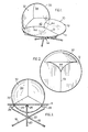
- Figure 1 is a perspective view of the apparatus of one embodiment of the present invention;
- Figure 2 is a top plan view of the apparatus of Figure 1;
- Figure 3 is a front elevation of the apparatus of Figure 1;
- Figure 4 is a side elevation of the apparatus of Figure 1;
- Figure 5 is a bottom plan view of the apparatus of Figure 1 without the deflecting element;
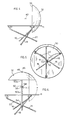
- Figure 6 is a side elevation of another embodiment of the apparatus of the present invention showing a vertical orientation of the deflecting element in phantom lines;
- Figure 7 is a partly exploded perspective view of still another embodiment of the present invention;
- Figure 8 is a partial cross-section of the apparatus of Figure 7;
- Figure 9 is a front elevation of still another embodiment of the present invention;
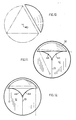
- Figure 10 is a representational plan view illustrating the preferred spherical sector for the spherical rebound surface;
- Figure 11 is a top plan view of the apparatus of Figure 1 illustrating the path of a ball rebounding off a spherical rebound surface of a configuration as illustrated in Figure 10;
- Figure 12 is a top plan view of the apparatus of Figure 1 illustrating another path of a ball rebounding off of a spherical rebound surface of a configuration as illustrated in Figure 10;
- Figure 13 is a perspective view of still another embodiment of the present invention; and
- Figure 14 is a side elevation of still another embodiment of the present invention.
- In a preferred embodiment of the invention, there is provided a table 10 having a generally planar
horizontal court 12 supported by atripod 14. - The
court 12 is preferably the upper surface of ahorizontal sheet 11 of rigid material, such as wood or plastic, with suitable reinforcement to prevent sagging. Thehorizontal sheet 11 is preferably an integral sheet, however it may be composed of any number of integrated pieces such that such pieces when assembled provide an integral surface for thecourt 12. - The
court 12 may be supported by any suitable structure, such as a pedestal, or by legs. Preferably support for thecourt 12 comprises atripod 14 having legs, 16, 18, 20 attached to the underside of thesheet 11 at points about the periphery thereof, each point being approximately equi-distant from the other two for maximum support. Thelegs common junction 22, each leg extending therebeyond to contact the ground or floor. Levellers may be included to ensure that thecourt 12 is properly level. Moreover,legs court 12. - Preferably each leg is attached to the underside of the
sheet 11, as aforesaid, by means of apin 26 removably received through opposed holes in abracket 28 and complementary holes through the upper end of the leg. Thus, thelegs sheet 11 simply by removal of thepins 26. - Cut out of the
court 12 adjacent to an edge thereof is a crescent-shaped aperture 30 having alip 31. A deflectingelement 32 having a concavespherical rebound surface 34 is mounted in theaperture 30 such that itsperipheral edge 33 is approximately orthogonal to thecourt 12. Theaperture 30 is wide enough to permit the deflectingelement 32 to be removably mounted therein with sufficient stability to retain the deflectingelement 32 in the desired vertical orientation, preferably such that approximately one quarter of thespherical rebound surface 34 depends below the level of thecourt 12. - The deflecting
element 32 is preferably composed of three equal sections of a rigid material such as wood or plastic which lock together tongue-in-groove or by means of tracks or clips or other known means which permit easy disassembly for transporting. Thespherical rebound surface 34 of the deflectingelement 32 consists of a portion of a sphere as described in greater detail below. - In use the apparatus is assembled as described above. Depending upon the rules agreed to between competing players, the players position themselves generally on opposite sides of the
centre line 13 on thecourt 12 forwardly of therebound surface 34 of the deflectingelement 32. A resilient ball can rebound in any permitted combination against thecourt 12 and therebound surface 34, although it is intended that the ball be propelled by the players toward therebound surface 34 to rebound therefrom onto thecourt 12. The ball may be propelled by the players by hand or by racquets utilized in known rebounding ball games or any equivalent thereof. - Utilizing the
notional centre 40 of thespherical rebound surface 34, as illustrated in Figure 4, a player may anticipate the angle of rebound of the ball striking thespherical rebound surface 34 by conceptualizing a radius from thenotional centre 40 to the point of contact of the ball on therebound surface 34. The angle of incidence of the ball relative to this imaginary radius will equal the angle of deflection of the ball relative thereto. A player may thus predict the direction that the ball will rebound off of therebound surface 34 for placement at a strategic location on thecourt 12. - As indicated above, in practice, the game contemplated by the subject invention is played differently from rebounding ball games played against a planar vertical backboard. In the latter case, in order to place the ball selectively further across the court, i.e. away from the player, the player can propel the ball to strike the backboard with the same force at correspondingly greater distances from himself. In the game of the present invention, in order to place the ball at selectively further points across the
court 12 the player can propel the ball to strike points on thespherical rebound surface 34 correspondingly closer to the player. - The same principle applies to depth placement, in that in games involving a planar backboard, the depth of the placement of the ball on the court increases as the ball strikes selectively higher positions on the planar backboard with the same force. In the apparatus of the present invention in order to place the ball deeper on the
court 12, i.e. further from the deflecting element, the player can propel the ball toward a correspondingly lower portion of thespherical rebound surface 34. Again the principle that angle of incidence equals angle of deflection applies, as described above. - Virtually the entire game is played against the upper half of the
spherical rebound surface 34. This portion of thespherical rebound surface 34 rebounds the ball downwardly toward thecourt 12. Thus, propelled toward an appropriate location in the upper half of therebound surface 34 the ball will land within the court regardless of the force of the rebound. Propelling the ball against the lower half of thespherical rebound surface 34 will cause the ball to rebound upwardly and, depending upon the force of the rebound, past the edge of thecourt 12. - The
court 12 preferably has cut out adjacent to the crescent-shapedaperture 30 an extension thereof defined by twoarcuate edges 44 having alip 31 and approximating the curvature of thespherical rebound surface 34 and extending between thecentre line 13 of thecourt 12 and the tips of the crescent shapedaperture 30. This provides anaperture 42 in thecourt 12 which can serve the purposes of both defining an out-of-play region of the court, if the ball drops through theaperture 42, and providing a means for enabling the ball to be directed upwardly through to thespherical rebound surface 34 from beneath the level of thecourt 12 in order to keep the ball in play. Theaperture 42 may be smaller or omitted entirely to render the game easier to play. - In another preferred embodiment, illustrated in Figure 6, a
hole 46 is presented through approximately the centre of the deflectingelement 32 for receiving apin 48 at the end of apost 50. Thepost 50 may be positioned through ahole 52 through the approximate centre of thecourt 12 and an annular ring orsleeve 54 forming thejunction 22 of thelegs tripod 14. Thepost 50 thus rests on the ground or floor and can support the deflecting element in a horizontal position to act as an umbrella protecting thecourt 12 from adverse weather conditions such as sunlight and precipitation. A plug (not shown) may be used to conceal thehole 46 when the game is in play. - The
post 50 is preferably composed of two sections, 50a and 50b, joined by areleasable hinge 56. Alever 58 which locks or releases thehinge 56 permits the deflectingelement 32 to be raised to a selected orientation between the vertical and the horizontal. - In another embodiment, the
post 50 may also be provided with anumbrella structure 70 spaced from the deflectingelement 32, as illustrated in Figure 14. In this embodiment the deflectingelement 32 has ahole 46 large enough to accept aconstricted extension 51 of thepost 50, with thepin 48 projecting therefrom which may be capped to secure theumbrella 70. This enables the deflectingelement 32 to pivot downwardly directly into theaperture 30, while theumbrella 70 is sufficiently spaced from the deflectingelement 32 that when pivoted downwardly it clears the margin of the court, and can act as a backdrop to capture balls propelled past the deflectingelement 32. Thepost 50 in this embodiment is not removed from thecourt 12 when the game is in play. When thepost 50 is upright the deflectingelement 32 is substantially concealed by theumbrella 70. - In still a further embodiment the apparatus of the present invention may be used as an outdoor or indoor table. In this embodiment the deflecting
element 32 can be stored underneath thesheet 11, nested on thelegs tripod 14, as illustrated in Figure 9, by detaching thesheet 11 from thetripod 14, and reattaching same after positioning thedeflectment element 32. Aninsert 60, preferably composed of the same material having the same thickness as thesheet 11 and congruent with the shape of theapertures apertures insert 60 has alip 61 complementary to thelip 31 of the aperture, as illustrated in Figure 8, to retain theinsert 60 in the aperture. The apparatus may then easily be converted back to the rebounding ball game embodiment for play when desired by removal of theinsert 60 and mounting of the deflectingelement 32. - The apparatus of the present invention may be constructed to any size suitable for the players. Preferably in the tabletop version the
court 12 is circular and approximately five feet in diameter. Preferably also thehorizontal sheet 11 is round, to conform with thecourt 12. Because of the manner in which the ball rebounds off of thespherical rebound surface 34 it has been determined that the most preferable shape for thecourt 12 is a circle, and for easiest movement by the players around thecourt 12, thehorizontal sheet 11 should similarly be circular and no larger than the court. - For a court of this size the
spherical rebound surface 34 is preferably approximately four feet in diameter at theperipheral edge 33, and represents the cap of a spherical sector of a sphere approximately 4.7 feet in diameter obtained when the plane of the spherical sector intersects one side of an equilateral triangle intersecting the great circle of the sphere, at right angles to the triangle, as illustrated in Figure 10. With arebound surface 34 of this configuration, a ball propelled from the side of the court barely glancing one side of theperipheral edge 33 of the deflectingelement 32 and rebounding off of the other side of thespherical rebound surface 34 at theperipheral edge 33 will not deflect past thecentre line 13, as illustrated in Figure 11. Furthermore, as illustrated in Figure 12, multiple rebounds are possible from a single shot. - Preferably also the
centre 40 of thespherical rebound surface 34 is in vertical alignment with the centre of thecourt 12, resulting in a margin of approximately 0.3 feet around the deflectingelement 32, as illustrated in Figure 2. This enables a player to propel the ball toward therebound surface 34 so that it rolls along therebound surface 34 and, once past theperipheral edge 33, can still land on thecourt 12 at the margin thereof. - The game to which the apparatus of the present invention is directed may be played as well on a fullcourt. A deflecting
element 62 having arebound surface 34 with the same configuration described above but suitably larger may be mounted on the floor or ground. Thecourt 12 may be delineated on the floor or ground forward of thespherical rebound surface 34, preferably proportionally having the same relative dimensions as those described above in connection with the tabletop version of the apparatus. Theapertures element 62 and an out-of-play zone as aforesaid. Alternatively, the deflectingelement 62 may be severed along itsperipheral edge 63 to form a bottom edge 64 upon which the deflectingelement 62 rests, andlines 65 may be drawn to delineate an out-of-play area of thecourt 12, as illustrated in Figure 13. The type of ball and, if desired, racquet used would be those more appropriate to a full-court sport such as racquetball or squash, or modifications thereof. - Having thus described the present invention, it will be obvious to those skilled in the art that various modifications and adaptations may be made without departing from the scope of the invention so described. The foregoing description is by way of nonlimiting example only.
Claims (15)
1. Apparatus for a rebounding ball game comprising a generally circular court 12 adapted for a generally horizontal orientation, and a deflecting element 32 having a forward spherical concave rebound surface 34 and a peripheral edge 33, adapted to be mounted generally vertically relative to the court 12 such that at least a substantial portion of the court 12 extends forwardly of the deflecting element 32 and at least a substantial portion of the deflecting element 32 extends upwardly from the court 12 with the peripheral edge 33 generally orthogonal thereto.
2. Apparatus as defined in claim 1 wherein the court 12 is adapted to be raised from the floor or ground.
3. Apparatus as defined in claim 2 wherein the court 12 is adapted to be supported by a detachable tripod 14.
4. Apparatus as defined in claim 3 wherein the tripod 14 is adapted to receive the deflecting element 32 in nested relation.
5. Apparatus as defined in claim 1 wherein the deflecting element 32 is adapted to be mounted such that approximately one-quarter of the rebound surface 34 depends downwardly from the court 12.
6. Apparatus as defined in claim 5 wherein the court 12 is provided with an aperture 30 adapted to receive the deflecting element 32.
7. Apparatus as defined in claim 1 wherein the court 12 is provided with an aperture defining an out-of-play region.
8. Apparatus as defined in claim 1 wherein the rebound surface 34 approximates the cap of a spherical sector obtained when the plane of the spherical sector intersects one side of an equilateral triangle intersecting the great circle of a sphere.
9. In combination, a table 10 having a generally planar elevated circular court 12 and a deflecting element 32 having a forward spherical concave rebound surface 34 and a peripheral edge 33, the deflecting element 32 being adapted to be mounted such that the peripheral edge 33 is generally vertical, at least a substantial portion of the court 12 extends forwardly of the rebound surface 34 and at least a substantial portion of the rebound surface 34 extends upwardly from the court 12.
10. The combination as defined in claim 9 wherein the court 12 is adapted to be supported by a detachable tripod 14.
11. The combination as defined in claim 10 wherein the tripod 14 is adapted to receive the deflecting element 32 in nested relation and including an insert 60 adapted to be removably received in an aperture in the court.
12. Apparatus for a rebounding ball game comprising a table 10 having legs 16, 18, 20 and a generally planar court 12 adapted for horizontal mounting thereon, and a deflecting element 32 having a forward spherical concave rebound surface 34 and a peripheral edge 33 and means for removably securing a support 50, whereby the deflecting element 32 can be displaced between a position wherein at least a substantial portion of the rebound surface 34 extends upwardly from the court 12, a substantial portion of the court 12 extends forwardly of the rebound surface 34 and the peripheral edge 33 is generally orthogonal to the court 12, and a position wherein the deflecting element 32 rests on the support 50 above the table 10 with the peripheral edge 33 generally horizontal to shield the court 12 from adverse weather conditions.
13. Apparatus as defined in claim 12 wherein the support comprises a post 50 having an upper portion 50a and a lower portion 50b connected by a hinge 56.
14. Apparatus as defined in claim 13 wherein the hinge 56 includes a locking mechanism 58 for maintaining the upper portion 50a of the post 50 in a selected orientation relative to the lower portion 50b of the post 50.
15. Apparatus as defined in claim 13 including an umbrella structure 70 adapted to be supported by the post 50 in spaced relation from the deflecting element 32 such that when the peripheral edge 33 is generally orthogonal to the court 12 the umbrella structure 70 creates a backdrop to capture stray shots and when the peripheral edge 33 is generally horizontal the umbrella structure 70 shields the deflecting element 32 and the court 12 from adverse weather conditions.
Applications Claiming Priority (2)
| Application Number | Priority Date | Filing Date | Title |
|---|---|---|---|
| US137569 | 1987-12-24 | ||
| US07/137,569 US4824108A (en) | 1987-12-24 | 1987-12-24 | Rebounding ball game |
Publications (2)
| Publication Number | Publication Date |
|---|---|
| EP0323091A2 true EP0323091A2 (en) | 1989-07-05 |
| EP0323091A3 EP0323091A3 (en) | 1990-01-31 |
Family
ID=22478039
Family Applications (1)
| Application Number | Title | Priority Date | Filing Date |
|---|---|---|---|
| EP88311976A Withdrawn EP0323091A3 (en) | 1987-12-24 | 1988-12-16 | Apparatus for a rebounding ball game |
Country Status (2)
| Country | Link |
|---|---|
| US (1) | US4824108A (en) |
| EP (1) | EP0323091A3 (en) |
Families Citing this family (9)
| Publication number | Priority date | Publication date | Assignee | Title |
|---|---|---|---|---|
| US5354051A (en) * | 1993-05-06 | 1994-10-11 | Fehrenbach Donald E | Ball return practice device |
| US5531449A (en) * | 1995-04-14 | 1996-07-02 | Denton; William H. | Portable stoopball striker |
| US20060284370A1 (en) * | 2005-06-20 | 2006-12-21 | Pai Li Business Co., Ltd. | Goal end board of a soccer playing table |
| DE102006057355B4 (en) | 2006-12-04 | 2020-01-09 | Steffen Baden | Miniature competition ball game, in particular table tennis game, with a playing surface in the form of a round table and a hollow cylindrical rebound wall |
| US9155952B2 (en) * | 2009-12-10 | 2015-10-13 | Tatsuya Yamanashi | Tennis training apparatus |
| US9243747B2 (en) * | 2010-10-15 | 2016-01-26 | Charles E. Ramberg | Shade structure |
| US8607714B2 (en) * | 2010-10-15 | 2013-12-17 | Charles E. Ramberg | Shade structure |
| USD912745S1 (en) | 2020-06-16 | 2021-03-09 | Robert S. Armell | Ball rebounding practice device |
| KR102694522B1 (en) * | 2021-12-29 | 2024-08-13 | 이진식 | A 365 ball apparatus for a team game |
Family Cites Families (13)
| Publication number | Priority date | Publication date | Assignee | Title |
|---|---|---|---|---|
| DE555523C (en) * | 1931-03-17 | 1932-07-23 | Heinrich Lustig | Tennis teaching aid with a curved wall that bounces back against the balls to hit |
| US2066159A (en) * | 1936-01-08 | 1936-12-29 | Emmanuel L Delyra | Deflector ball game |
| US2174884A (en) * | 1937-02-19 | 1939-10-03 | Henry W Kachel | Apparatus for table tennis games |
| FR855057A (en) * | 1939-01-18 | 1940-05-01 | New improvements to parks or playgrounds | |
| US2781194A (en) * | 1953-08-07 | 1957-02-12 | George H Forsyth | Bouncing ball game apparatus having a sound strip |
| US3062544A (en) * | 1959-08-12 | 1962-11-06 | Charles W Viets | Collapsible game table |
| US3059927A (en) * | 1960-10-19 | 1962-10-23 | Arthur J Kamp | Ball game |
| US3088735A (en) * | 1961-01-13 | 1963-05-07 | Theodore W Clark | Rebound board for table tennis |
| US3782435A (en) * | 1972-06-13 | 1974-01-01 | R Sherman | Table protector |
| US3968967A (en) * | 1975-03-28 | 1976-07-13 | Nally Phillip L | Symmetrically arranged, hemispherical ball rebounding elements |
| US4134585A (en) * | 1976-03-26 | 1979-01-16 | Alex Semon | Table tennis return board |
| AU536542B2 (en) * | 1979-07-19 | 1984-05-10 | Guenter Arndt | Modified table-tennis game |
| US4478420A (en) * | 1983-03-04 | 1984-10-23 | Sowards Gregory E | Soccer training and practice device |
-
1987
- 1987-12-24 US US07/137,569 patent/US4824108A/en not_active Expired - Fee Related
-
1988
- 1988-12-16 EP EP88311976A patent/EP0323091A3/en not_active Withdrawn
Also Published As
| Publication number | Publication date |
|---|---|
| US4824108A (en) | 1989-04-25 |
| EP0323091A3 (en) | 1990-01-31 |
Similar Documents
| Publication | Publication Date | Title |
|---|---|---|
| US4492380A (en) | Arena type game | |
| US5692979A (en) | Multi-purpose game device | |
| US5584480A (en) | Portable sports target frame | |
| US4709929A (en) | Game board | |
| US4203592A (en) | Horseshoe type game device | |
| US5050889A (en) | Portable tossing game and target assembly | |
| US3897948A (en) | Football place-kicking device | |
| US5566948A (en) | Bouncing ball game | |
| US20050197197A1 (en) | Golf chipping target and game | |
| US5580320A (en) | Target green for golf practice | |
| US5509652A (en) | Hockey practice alley | |
| US5553863A (en) | Flexible two-sided multiple-sport goal | |
| US20050288129A1 (en) | Method and apparatus for practicing pitching a baseball | |
| US4824108A (en) | Rebounding ball game | |
| US4198048A (en) | Tossing game apparatus | |
| US4453713A (en) | Lawn game with vertically slidable targets | |
| US20030228943A1 (en) | Strike zone pitching backstop | |
| US3778060A (en) | Target for use on water or land | |
| US4339132A (en) | Lacrosse goal | |
| US11833400B1 (en) | Cornhole training device | |
| US3540734A (en) | Golfing target | |
| US3920245A (en) | Ball game | |
| US6220975B1 (en) | Swimming pool water game goal apparatus | |
| US7238127B2 (en) | Limited contact athletic game | |
| US4441719A (en) | Balloon game |
Legal Events
| Date | Code | Title | Description |
|---|---|---|---|
| PUAI | Public reference made under article 153(3) epc to a published international application that has entered the european phase |
Free format text: ORIGINAL CODE: 0009012 |
|
| AK | Designated contracting states |
Kind code of ref document: A2 Designated state(s): CH DE ES FR GB IT LI NL SE |
|
| PUAL | Search report despatched |
Free format text: ORIGINAL CODE: 0009013 |
|
| AK | Designated contracting states |
Kind code of ref document: A3 Designated state(s): CH DE ES FR GB IT LI NL SE |
|
| STAA | Information on the status of an ep patent application or granted ep patent |
Free format text: STATUS: THE APPLICATION IS DEEMED TO BE WITHDRAWN |
|
| 18D | Application deemed to be withdrawn |
Effective date: 19900801 |