EP0323051A2 - Verfahren zum Steuern eines Gleitschutz-Bremssystems - Google Patents
Verfahren zum Steuern eines Gleitschutz-Bremssystems Download PDFInfo
- Publication number
- EP0323051A2 EP0323051A2 EP88311505A EP88311505A EP0323051A2 EP 0323051 A2 EP0323051 A2 EP 0323051A2 EP 88311505 A EP88311505 A EP 88311505A EP 88311505 A EP88311505 A EP 88311505A EP 0323051 A2 EP0323051 A2 EP 0323051A2
- Authority
- EP
- European Patent Office
- Prior art keywords
- sector
- phase plane
- boundary
- wheel
- control method
- Prior art date
- Legal status (The legal status is an assumption and is not a legal conclusion. Google has not performed a legal analysis and makes no representation as to the accuracy of the status listed.)
- Granted
Links
Images
Classifications
-
- B—PERFORMING OPERATIONS; TRANSPORTING
- B60—VEHICLES IN GENERAL
- B60T—VEHICLE BRAKE CONTROL SYSTEMS OR PARTS THEREOF; BRAKE CONTROL SYSTEMS OR PARTS THEREOF, IN GENERAL; ARRANGEMENT OF BRAKING ELEMENTS ON VEHICLES IN GENERAL; PORTABLE DEVICES FOR PREVENTING UNWANTED MOVEMENT OF VEHICLES; VEHICLE MODIFICATIONS TO FACILITATE COOLING OF BRAKES
- B60T8/00—Arrangements for adjusting wheel-braking force to meet varying vehicular or ground-surface conditions, e.g. limiting or varying distribution of braking force
- B60T8/17—Using electrical or electronic regulation means to control braking
- B60T8/176—Brake regulation specially adapted to prevent excessive wheel slip during vehicle deceleration, e.g. ABS
- B60T8/1763—Brake regulation specially adapted to prevent excessive wheel slip during vehicle deceleration, e.g. ABS responsive to the coefficient of friction between the wheels and the ground surface
- B60T8/17636—Microprocessor-based systems
-
- B—PERFORMING OPERATIONS; TRANSPORTING
- B60—VEHICLES IN GENERAL
- B60T—VEHICLE BRAKE CONTROL SYSTEMS OR PARTS THEREOF; BRAKE CONTROL SYSTEMS OR PARTS THEREOF, IN GENERAL; ARRANGEMENT OF BRAKING ELEMENTS ON VEHICLES IN GENERAL; PORTABLE DEVICES FOR PREVENTING UNWANTED MOVEMENT OF VEHICLES; VEHICLE MODIFICATIONS TO FACILITATE COOLING OF BRAKES
- B60T8/00—Arrangements for adjusting wheel-braking force to meet varying vehicular or ground-surface conditions, e.g. limiting or varying distribution of braking force
- B60T8/17—Using electrical or electronic regulation means to control braking
- B60T8/1755—Brake regulation specially adapted to control the stability of the vehicle, e.g. taking into account yaw rate or transverse acceleration in a curve
Definitions
- the invention generally relates to automated anti-skid braking systems. More specifically, the invention concerns control methods for determining which of a number of available brake commands will be issued at a given point in time during an anti-skid braking sequence.
- ABS Automatically controlled anti-skid braking systems
- the first goal of an ABS is to avoid front wheel lock-up. Under such a condition, one loses "steerability".
- the second goal of a typical ABS is to avoid "fish-tailing" or rear-end instability.
- the third goal of an ABS is to minimize the stopping distance. It has been found that the stopping distance of a vehicle may be made shorter if the wheels are operated at low slip rather than in a fully locked or skid condition (the effective coefficient of friction is greater at lower slip than at full slip).
- the typical ABS attempts to optimize stopping distance, steerability and rear-end stability during so-called “panic-stops".
- a typical ABS control method one desires a high brake torque "apply” rate for quick response. Additionally, one needs a high "release” rate, if the condition of lock-up is sensed as about to begin.
- the conditions of "apply”, “hold” and “release” refer respectively to increasing, constant and decreasing brake pressure or resulting brake torque.
- the apply state means brake torque is being increased, the release state means that brake torque is being decreased, while the hold state indicates that the brake torque is being maintained constant.
- step-up and step-down basically interposes a hold state between any apply and release sequence. For example, under a step-up, one would enter an apply state, then enter a hold state perhaps longer than the apply state before entering another apply state, and alternating thereafter. Functionally, such an approach mimics a slow apply condition. Conversely, in a step-down, one would have a release state followed by a hold state and so on to provide a type of "slow release".
- ABS control method in accordance with the present invention is characterised over the prior art by the features specified in the characterising portion of Claim 1.
- the method for determining a desired one of a plurality of available brake control actions involves the steps of partitioning a phase plane having coordinates defined by wheel slip and wheel acceleration into a predetermined number of sectors, each meeting at a common point in the plane and each sector representing one of the desired brake control actions. Wheel slip and acceleration are estimated, and the phase plane is examined at a coordinate point defined by the slip and acceleration estimates. From the phase plane examination, one can determine the sector containing the point and may then issue a command designating one of the desired brake control actions in accordance with the determined sector.
- ABS control method limits wheel lock-up to maintain steerability and lateral stability of the vehicle during panic stops.
- phase plane is a natural and classical tool for studying the behaviour of low order nonlinear arrangements. It is particularly useful when studying "bang-bang" control arrangements which use lines in the phase plane as switching boundaries.
- phase plane may be used to develop ABS control methods following the principles of the invention.
- One of the most important criteria for an ABS control method is its robustness to parameter variations. Large variations are expected in several parameters including vehicle speed, road surface, brake fluid viscosity, and drive train effective inertia. Any ABS control method must be able to give acceptable performance as-these and other parameters are varied.
- the entire initial condition problem may be solved by plotting the path resulting from a sufficiently large number of different initial conditions. No two paths may cross, although two or more paths may converge and neighbouring paths may diverge. From any initial condition there is a unique path that the solution of the above set of differential equations will follow; if paths could cross, there would be two different paths from the crossing point.
- Step Up is a sequence of Applys and Holds. This is approximated below as a slow Apply.
- the slip, s is a function of both ⁇ and v.
- v is constant. This simplifies the computation of the time rate of change of s and avoids the introduction of an additional variable, v, into Eq. (10) giving:
- Eq. (13) can be put in the form of Eq. (3) if ais identified with y and -s is identified with x. In a slight variation from tradition, plots of avs. s will be described as the phase plane.
- I depends on the effective moment of inertia of the wheel - including the drive train, the rolling radius and wheel centre height, and the instantaneous normal force.
- the effective moment of inertia can vary by as much as an order of magnitude, and the normal force will vary by a large fraction of its nominal value in severe manoeuvres and due to loading variations.
- the rate of change of brake torque depends on the vehicle velocity and the rate of change of brake torque as well as the wheel centre height and the normal force.
- the vehicle velocity variation over which a typical ABS should operate covers about two orders of magnitude from 1.6-4.8 kph (1-3 mph) at the low end to 200-290 kph (120-180 mph) at the high end.
- the rate of change of brake torque will vary due to ⁇ 30% variations in specific torque and variations in hydraulic fluid flow rates through orifices. The flow rates depend on both the temperature and the pressure difference across the orifice.
- ⁇ eff is an explicit function of slip, is an explicit function of slip. It is also a function of the road surface and the slip angle. Road surface variations can change the slope of the a-slip curve at low slip by an order of magnitude and change the location of the maximum coefficient of friction. As the slip angle increases from zero, the longitudinal friction coefficient, ⁇ eff decreases at increasing values of slip. The decrease is greater at low slip than at high slip, resulting in a shift of the maximum coefficient of friction to higher values of slip, s.
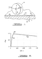
- ⁇ -slip curves Plots of the effective longitudinal friction coefficient, ⁇ eff vs. longitudinal slip, s are called " ⁇ -slip curves".
- Typical a-slip curves are characterised by a maximum at some relatively low - 5% to 30% - value of slip, dropping to zero at zero slip and decreasing gradually from the peak at higher values of slip.
- the peak varies from about 1.0 on dry surfaces to 0.1 on ice.
- the features to note with reference to the 4-slip curve of Figure 2 are that at low slip, the effective coefficient of friction is zero, while at high slip, the coefficient of friction is relatively high.
- the coefficient of friction shows a peak 200 at an intermediate value of slip. To the left of peak 200 is the stable region 201, while to the right of peak 200 is the unstable region 202.
- the lateral coefficient of friction is highest at zero slip and monotonically decreases as slip increases.
- the optimal ABS attempts to operate in a region of slip where both lateral and longitudinal forces are relatively high.
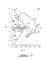
- the three-sector ABS control method of the present invention utilizes the phase plane depicted in Figure 3.
- the phase plane is defined by coordinates of slip and wheel angular acceleration a, and the plane is divided into three pie or wedge shaped sectors; Apply or A sector 302, Hold or H sector 303 and Release or R sector 301.
- Zero angular acceleration is depicted along dashed line 320, while the sectors are divided by linear boundaries - the boundary between the Release and Apply regions being designated 331, the boundary between the Apply and Hold regions being designated 332 and the boundary between the Hold and Release sectors designated as 330.
- the three-sector ABS control method works as follows. Starting in the Apply region A, a stable region of the a-slip curve focuses most elements of the set of possible paths (shown as dotted lines) to a line 380 and then to a point 355 at the Apply/Hold boundary line 332. The slopes of the paths in the A and H regions are such that the ABS control method will switch back and forth between Apply and Hold sectors while moving along the switching curve. This feature or inherent characteristic of this phase plane combines a pure Apply region followed by switching between the Apply and Hold sectors and automatically provides the prior art function of step-up mode without the necessity for providing specific implementing logic.
- the phase plane will be traversed along a typical path in a counter-clockwise direction, and once the path begins to nearly repeat itself, a path sweeping through 360° is termed a "limit cycle". It is desirable to maintain the limit cycle relatively large and non-collapsing toward the centre point 340 at which all three sectors meet, since this enables better slip, velocity, and acceleration state estimates while using the phase plane control approach.
- a typical limit cycle shown as path 310 in Figure 3 begins in the Release or R region at point 351, crosses between regions of negative and positive angular acceleration at point 352 and continues to boundary line 331 with the Apply or A region at point 353.
- the direction traversed along the path is shown by arrows 301 a and 301 b.
- the path continues and crosses back into a region of negative acceleration at point 354 whereupon it is caused by stable region 201 ( Figure 2) to converge to point 355 located at boundary line 332 between the Apply and Hold regions.
- the boundary line By choosing the boundary line to have the form of Eq. (17), we can retain the same angle between the boundary line and the path line at all vehicle speeds. Accordingly, the vehicle speed estimate will be used to vary the slope of the boundary lines.
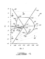
- a preferred type of phase plane sector layout utilizes four sectors as seen in Figure 4.
- the fourth sector is an additional Hold region 402 added between the Apply and Release regions 403 and 401 respectively, by adding a boundary line 431 in the upper right hand quadrant of the plane shown.
- the purpose of adding the fourth sector is that in the three sector algorithm, a large Release region results in an excessive decrease in brake pressure.
- an additional Hold region was interposed between the Release region and the Apply region when moving in a counter-clockwise direction about the phase plane. It is believed this fourth sector improves stopping distance.
- a typical limit cycle path in the phase plane of Figure 4 is designated 410, and its direction is indicated by arrowheads 401a a and 401b.
- the path will then proceed across the zero line of acceleration 420 at point 452 up to sector boundary line 431 at point 453.
- the locus of possible paths in this added Hold region 402 is substantially horizontal or parallel to the slip axis of the phase plane.
- the path proceeds substantially parallel to the slip axis to boundary line 432 at point 454 whereupon it descends through the Apply region to cross zero acceleration line 420 at point 455, whereupon the stable a-slip region will cause the path to converge to a line 480 and then to a point 456 located at boundary line 433 between the Apply and Hold regions 403 and 404 respectively.
- the path will again automatically switch in a saw tooth fashion between the Hold and Apply regions as depicted in region 457 until it intersects a curve parallel to the ⁇ -slip curve at point 458.
- the path then follows the curve up to its peak at 459 and then to point 461 on boundary line 430 separating the Hold and Release regions 404 and 401, respectively. At this point, due to overshoot, the path will descend to point 462 whereupon a new limit cycle will be initiated at path 470.
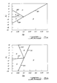
- the four-sector approach may also have adaptive control wherein different slopes for the sector boundary lines will be chosen as a function of the vehicle speed.
- phase planes of Figures 5A and 56 are set forth in the representative phase planes of Figures 5A and 56.
- the slopes of the sector boundary lines are lower than those set forth in Figure 5B.
- the phase plane for Figure 5A would be used at lower speeds, for example on the order of 9.7 kph (6 mph), while the phase plane sections of Figure 5B would be used at relatively higher vehicle speeds, for example on the order of 38.6 kph (24 mph).
- a family of phase planes, one for each desired range of vehicle speeds could be advantageously employed in an ABS control method adapted to vehicle speed.
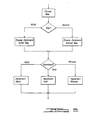
- Figure 6 depicts, in flow chart form, the overall control method block diagram. Given estimates of wheel slip, wheel angular speed, and wheel angular acceleration for a particular wheel, (using known elements such as variable reluctance transducers) the control algorithm chooses which command to send to the hydraulic sub-system: Apply, Hold or Release.
- phase plane maps Two types are available, an initial map and a normal or anti-skid map.
- the first step as set forth in Figure 6 is to select which type of map to use. This decision is based on the following sequential logic:
- the initial map is the .map of brake commands used in typical driving and used in the initial phase of entering an anti-skid mode.
- the ABS capability does not come into play.
- limits of slip and wheel acceleration are exceeded, a release of brake pressure is begun and the arrangement begins ABS cycling.
- the normal or anti-skid phase plane map is divided into sectors, preferably into four sectors, and the command selected depends upon which sector holds the current estimate of slip and wheel acceleration.
Landscapes
- Engineering & Computer Science (AREA)
- Transportation (AREA)
- Mechanical Engineering (AREA)
- Microelectronics & Electronic Packaging (AREA)
- Regulating Braking Force (AREA)
Applications Claiming Priority (2)
| Application Number | Priority Date | Filing Date | Title |
|---|---|---|---|
| US07/138,540 US4855916A (en) | 1987-12-28 | 1987-12-28 | Anti-skid braking system control method |
| US138540 | 1993-10-15 |
Publications (3)
| Publication Number | Publication Date |
|---|---|
| EP0323051A2 true EP0323051A2 (de) | 1989-07-05 |
| EP0323051A3 EP0323051A3 (en) | 1990-03-07 |
| EP0323051B1 EP0323051B1 (de) | 1991-11-06 |
Family
ID=22482488
Family Applications (1)
| Application Number | Title | Priority Date | Filing Date |
|---|---|---|---|
| EP88311505A Expired - Lifetime EP0323051B1 (de) | 1987-12-28 | 1988-12-05 | Verfahren zum Steuern eines Gleitschutz-Bremssystems |
Country Status (3)
| Country | Link |
|---|---|
| US (1) | US4855916A (de) |
| EP (1) | EP0323051B1 (de) |
| DE (1) | DE3866094D1 (de) |
Cited By (1)
| Publication number | Priority date | Publication date | Assignee | Title |
|---|---|---|---|---|
| EP0461373A1 (de) * | 1990-06-02 | 1991-12-18 | Mercedes-Benz Ag | Verfahren zur Bestimmung eines optimierten Schlupfsollwertes eines Kraftfahrzeuges |
Families Citing this family (5)
| Publication number | Priority date | Publication date | Assignee | Title |
|---|---|---|---|---|
| US4991103A (en) * | 1989-11-01 | 1991-02-05 | General Motors Corporation | Rear wheel anti-lock brake controller |
| JPH06122332A (ja) * | 1992-10-09 | 1994-05-06 | Nippondenso Co Ltd | 車両のスリップ制御装置 |
| US6292735B1 (en) | 1998-08-10 | 2001-09-18 | Ford Global Technologies, Inc. | Wheelslip regulating brake control |
| US6370467B1 (en) | 1998-08-10 | 2002-04-09 | Ford Global Technologies, Inc. | Method of calculating optimal wheelslips for brake controller |
| US6356832B1 (en) * | 2000-11-28 | 2002-03-12 | Ford Global Technologies, Inc. | Anti-lock brake control system having enhanced straightline braking efficiency |
Family Cites Families (8)
| Publication number | Priority date | Publication date | Assignee | Title |
|---|---|---|---|---|
| CA1002153A (en) * | 1973-04-25 | 1976-12-21 | James E. Rau | Anti-skid control system |
| GB2130757B (en) * | 1982-10-12 | 1987-05-07 | Honda Motor Co Ltd | Anti-slip systems for wheeled vehicles |
| JPS59209940A (ja) * | 1983-05-16 | 1984-11-28 | Nissan Motor Co Ltd | 車輪情報演算装置 |
| DE3326959A1 (de) * | 1983-07-27 | 1985-02-07 | Robert Bosch Gmbh, 7000 Stuttgart | Antiblockierregelsystem |
| DE3345729A1 (de) * | 1983-12-17 | 1985-06-27 | Alfred Teves Gmbh, 6000 Frankfurt | Verfahren und schaltungsanordnung zur unterdrueckung unerwuenschter regelvorgaenge in schlupfgeregelten bremsanlagen |
| DE3435870A1 (de) * | 1984-09-29 | 1986-04-10 | Robert Bosch Gmbh, 7000 Stuttgart | Antiblockierregelsystem |
| JPS62122859A (ja) * | 1985-11-25 | 1987-06-04 | Toyota Motor Corp | 車両用アンチスキツド型ブレ−キシステム |
| JPH0620877B2 (ja) * | 1986-04-23 | 1994-03-23 | トヨタ自動車株式会社 | 車両の加速スリツプ制御方法 |
-
1987
- 1987-12-28 US US07/138,540 patent/US4855916A/en not_active Expired - Lifetime
-
1988
- 1988-12-05 EP EP88311505A patent/EP0323051B1/de not_active Expired - Lifetime
- 1988-12-05 DE DE8888311505T patent/DE3866094D1/de not_active Expired - Fee Related
Cited By (1)
| Publication number | Priority date | Publication date | Assignee | Title |
|---|---|---|---|---|
| EP0461373A1 (de) * | 1990-06-02 | 1991-12-18 | Mercedes-Benz Ag | Verfahren zur Bestimmung eines optimierten Schlupfsollwertes eines Kraftfahrzeuges |
Also Published As
| Publication number | Publication date |
|---|---|
| DE3866094D1 (de) | 1991-12-12 |
| EP0323051B1 (de) | 1991-11-06 |
| US4855916A (en) | 1989-08-08 |
| EP0323051A3 (en) | 1990-03-07 |
Similar Documents
| Publication | Publication Date | Title |
|---|---|---|
| US5358317A (en) | Fuzzy logic electric vehicle regenerative antiskid braking and traction control system | |
| US4947332A (en) | Road surface estimation | |
| US5471386A (en) | Vehicle traction controller with torque and slip control | |
| EP0361708B1 (de) | Regler für regeneratives Bremssystem | |
| EP0397328B1 (de) | Fahrzeug-Antriebssteuervorrichtung und -verfahren | |
| JP2681930B2 (ja) | サーボ制御装置 | |
| US20030036839A1 (en) | Adaptive powertrain braking control with grade, mass, and brake temperature | |
| CN106882180B (zh) | 一种无人驾驶履带车的起步控制方法 | |
| JPH0952538A (ja) | 車両の四輪駆動制御装置 | |
| US4859002A (en) | Antiskid brake control device | |
| EP0397330A2 (de) | Fahrzeug-Antriebssteuervorrichtungsverfahren | |
| CN116507511A (zh) | 使车轮-地面的法向力根据牵引力变化 | |
| KR20230114798A (ko) | 개선된 연산 방법을 통한 차량 예측 제어 방법 및 차량용 운전 제어 장치 | |
| EP0323051A2 (de) | Verfahren zum Steuern eines Gleitschutz-Bremssystems | |
| US5071199A (en) | Antilock brake system with motor current control | |
| EP0397329B1 (de) | Fahrzeug-Antriebssteuervorrichtung | |
| KR20230092060A (ko) | 차량용 최적 배터리 효율 운전 제어 방법 | |
| US5394954A (en) | Engine control apparatus | |
| WO2025111527A1 (en) | Electric vehicle powertrain control algorithm | |
| DE102020213442A1 (de) | Verfahren und Steuergerät zum Bestimmen von Haftungsbedingungen zwischen einer Fahrbahn und zumindest einem Rad eines Fahrzeugs | |
| CN115952641B (zh) | 基于元胞自动机的双车道自动-手动驾驶车辆交通流仿真方法 | |
| JP3985666B2 (ja) | 車両の駆動力制御装置 | |
| JP2605984B2 (ja) | 車両の制動制御装置 | |
| US6088646A (en) | Fuzzy logic antiskid control system for aircraft | |
| JP3772486B2 (ja) | アンチスキッド制御装置 |
Legal Events
| Date | Code | Title | Description |
|---|---|---|---|
| PUAI | Public reference made under article 153(3) epc to a published international application that has entered the european phase |
Free format text: ORIGINAL CODE: 0009012 |
|
| AK | Designated contracting states |
Kind code of ref document: A2 Designated state(s): DE FR GB |
|
| PUAL | Search report despatched |
Free format text: ORIGINAL CODE: 0009013 |
|
| AK | Designated contracting states |
Kind code of ref document: A3 Designated state(s): DE FR GB |
|
| 17P | Request for examination filed |
Effective date: 19900427 |
|
| 17Q | First examination report despatched |
Effective date: 19901012 |
|
| GRAA | (expected) grant |
Free format text: ORIGINAL CODE: 0009210 |
|
| AK | Designated contracting states |
Kind code of ref document: B1 Designated state(s): DE FR GB |
|
| REF | Corresponds to: |
Ref document number: 3866094 Country of ref document: DE Date of ref document: 19911212 |
|
| ET | Fr: translation filed | ||
| PLBE | No opposition filed within time limit |
Free format text: ORIGINAL CODE: 0009261 |
|
| STAA | Information on the status of an ep patent application or granted ep patent |
Free format text: STATUS: NO OPPOSITION FILED WITHIN TIME LIMIT |
|
| 26N | No opposition filed | ||
| PGFP | Annual fee paid to national office [announced via postgrant information from national office to epo] |
Ref country code: GB Payment date: 20001127 Year of fee payment: 13 |
|
| PG25 | Lapsed in a contracting state [announced via postgrant information from national office to epo] |
Ref country code: GB Free format text: LAPSE BECAUSE OF NON-PAYMENT OF DUE FEES Effective date: 20011205 |
|
| REG | Reference to a national code |
Ref country code: GB Ref legal event code: IF02 |
|
| GBPC | Gb: european patent ceased through non-payment of renewal fee |
Effective date: 20011205 |
|
| PGFP | Annual fee paid to national office [announced via postgrant information from national office to epo] |
Ref country code: FR Payment date: 20041216 Year of fee payment: 17 |
|
| PGFP | Annual fee paid to national office [announced via postgrant information from national office to epo] |
Ref country code: DE Payment date: 20050225 Year of fee payment: 17 |
|
| PG25 | Lapsed in a contracting state [announced via postgrant information from national office to epo] |
Ref country code: DE Free format text: LAPSE BECAUSE OF NON-PAYMENT OF DUE FEES Effective date: 20060701 |
|
| PG25 | Lapsed in a contracting state [announced via postgrant information from national office to epo] |
Ref country code: FR Free format text: LAPSE BECAUSE OF NON-PAYMENT OF DUE FEES Effective date: 20060831 |
|
| REG | Reference to a national code |
Ref country code: FR Ref legal event code: ST Effective date: 20060831 |