EP0323033A2 - Tragevorrichtung für drei Matrizen in einer Maschine zum Herstellen von Glasgegenständen - Google Patents
Tragevorrichtung für drei Matrizen in einer Maschine zum Herstellen von Glasgegenständen Download PDFInfo
- Publication number
- EP0323033A2 EP0323033A2 EP88311274A EP88311274A EP0323033A2 EP 0323033 A2 EP0323033 A2 EP 0323033A2 EP 88311274 A EP88311274 A EP 88311274A EP 88311274 A EP88311274 A EP 88311274A EP 0323033 A2 EP0323033 A2 EP 0323033A2
- Authority
- EP
- European Patent Office
- Prior art keywords
- mould
- support
- arms
- arm
- moulds
- Prior art date
- Legal status (The legal status is an assumption and is not a legal conclusion. Google has not performed a legal analysis and makes no representation as to the accuracy of the status listed.)
- Granted
Links
Images

Classifications
-
- C—CHEMISTRY; METALLURGY
- C03—GLASS; MINERAL OR SLAG WOOL
- C03B—MANUFACTURE, SHAPING, OR SUPPLEMENTARY PROCESSES
- C03B9/00—Blowing glass; Production of hollow glass articles
- C03B9/30—Details of blowing glass; Use of materials for the moulds
- C03B9/34—Glass-blowing moulds not otherwise provided for
- C03B9/353—Mould holders ; Mould opening and closing mechanisms
- C03B9/3532—Mechanisms for holders of half moulds moving by rotation about a common vertical axis
- C03B9/3535—Mechanisms for holders of half moulds moving by rotation about a common vertical axis with the half moulds parallel upon opening and closing
Definitions
- This invention is concerned with a supporting mechanism for supporting mould side portions of three moulds in a glassware forming machine, e.g. of the individual section type.
- the supporting mechanisms for the mould side portions comprise two arms each arranged, on the application of a mould closure force thereto, to move in predetermined directions from mould open positions thereof to mould closed positions thereof and to remain in the mould closed positions during a moulding operation of the machine.
- the arms move towards one another arcuately about a common vertical axis to reach their mould closed positions whereas in other machines the arms move linearly towards one another.
- one or more mould side portions (there may be as many as four) supported on each arm cooperate with mould side portions supported on the other arm to define mould cavities in which molten glass can be moulded.
- the arms On the application of a mould opening force, the arms return to their mould open positions, by moving in the opposite direction to said predetermined direction. In their mould open positions, the mould side portions supported on each arm are separated from those supported on the other arm to allow removal of moulded glass.
- Such supporting mechanisms are used both for "blank” moulds for moulding gobs of molten glass into parisons, by a pressing or a blowing operation, and also for "finish" moulds for moulding parisons into completed articles of glassware.
- the supporting mechanisms comprise an upper and a lower support mounted on each arm.
- the upper and lower support on an arm cooperate in supporting said one or more mould side portions.
- the supports are generally mounted on the arm for limited pivoting movements and each defines a recess into which a hook-shaped projection of the mould side portion extends so that the mould side portion hangs on the supports.
- a mould side portion rests on the upper support while the lower support prevents the mould side portion from pivoting relative to the upper support.
- the invention provides a supporting mechanism for supporting mould side portions of three moulds in a glassware forming machine, the mechanism comprising two opposed arms each arranged, on the application of a mould closure force thereto, to move from a mould open position thereof to a mould closed position thereof and to remain in the mould closed position during a moulding operation of the machine, and, on the application of a mould opening force thereto, to return to the mould open position thereof, each of the arms being arranged to support three mould side portions which, when the arms are in their mould closed positions, each engages a mould side portion supported by the other arm to cooperate therewith in defining a mould cavity and which, when the arms are in their mould open positions, is separated from said mould side portion to allow removal of moulded glass, the mechanism also comprising supports pivotally mounted on the said arms and arranged to support three mould side portions, characterised in that the supports comprise a triple support pivotally mounted on one arm and arranged to support three mould side portions, a double support pivotally mounted on the other arm and arranged to support two mould side portions and
- the mould closure force is found to balance substantially equally between the three moulds.
- the force balancing across an individual mould may be improved if said double support supports two further single supports each of which is arranged to support one of the mould side portions supported by the double support and each of which is pivotally mounted on the double support, when the arms are in their mould closed positions, the pivots of said single supports being aligned with the centre-lines of their respective associated moulds.
- the force balancing may be improved if said double support is arranged to slide to a limited extent relative to its pivot in a direction normal to said line passing halfway between the centre mould and one of the other moulds.
- the force may be balanced heightwise if each of said triple, double and single supports comprises an upper support plate and a lower support plate arranged to cooperate in supporting mould side portions, the upper and lower support plates mounted on at least one of the arms being mounted for limited movement in a horizontal plane, and the mechanism also comprises at least one force apportioning member arranged, when the arms are in their mould closed positions, to apportion the mould closure force between the upper and lower support plates, the force apportioning member being mounted on the arm to pivot about a horizontal axis between the upper and lower support plates and extending normal to the predetermined direction of movement of the arm, the force apportioning member also being pivotally connected to said upper and lower support plates.
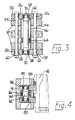
- the first illustrative supporting mechanism shown in Figures 1 to 3 is for supporting finish mould side portions 10 (which have been omitted from Figure 1) of three moulds in a glassware forming machine of the individual section type.
- a modification of the first illustrative mechanism can support three blank moulds instead of three finish moulds.
- the mechanism comprises two opposed arms 12 and 14 which are mounted, in conventional manner, on a common vertical pivot pin 16.
- a mould opening and closing mechanism (not shown) of conventional construction is provided for applying a mould closure force or a mould opening force to the arms 12 and 14, the forces being applied via links (not shown) pivotally connected to the arms 12 and 14 by pins 18 mounted on the arms.
- the moulds may move linearly according to the so-called AIS principle.
- the arms 12 and 14 are each arranged to move arcuately about the pin 16 from a mould open position thereof (not shown) to a mould closed position thereof (shown in Figure 1).
- the arms 12 and 14 approach one another with the arm 12 moving clockwise and the arm 14 moving anti-clockwise.
- the arms 12 and 14 are arranged to remain in their mould closed positions during a moulding operation of the machine, being held there by continued application of the mould closure force.
- the arms 12 and 14 are each arranged to return to their mould open position by reversing their arcuate movements about the pin 16.
- the three mould side portions 10 supported by each arm engage the three mould side portions supported by the other arm and with bottom plates 20 and cooperate therewith to define three mould cavities 22 in which molten glass can be moulded.
- the mould side portions 10 supported by the arm 12 are separated from those supported by the arm 14 to allow removal of moulded glass.
- the arms 12 and 14 are both formed as three horizontally-extending plates interconnected by vertical bracing members (see Figure 2).
- the arm 12 supports two vertically-extending pivot pins 24 and 26 and two pivot limiting pins 28 and 30. Pivotally mounted on the pin 24 on top of the arm 12 is an upper double support plate 32 which cooperates with a lower double support plate (not shown) also pivotally mounted on the pin 24 but mounted beneath the arm 12, being supported by a washer (not shown) mounted on the pin 24.
- the two double support plates together form a double support arranged to cooperate in supporting two mould side portions 10 and, to this end, the upper double support plate has two arcuate slots 34 in an upper surface thereof into which depending portions of hook-shaped projections 36 of the mould side portions 10 extend to mount the portions 10 on the support.
- the upper slots 34 each have a gap 38 therein in which a location block 33 is mounted over which a slot in the projection 36 of the mould side portion 10 fits to prevent the hook-shaped portions 36 from moving along the slots 34.
- the lower double support plate (not shown) has two short straight slots 35 into which lower hook-shaped projections 37 of the side portions 10 fit to prevent the side portions 10 from tilting (the slots 35 of the double support are not visible in the drawings but are similar to those shown in Figure 2).
- the pivot limiting pin 28 projects into clearance holes (not shown) in both the double support plates to limit the pivoting thereof about the pin 24 which is aligned with a line perpendicular to the parting line of the mould portions 10 and passing centrally between the two mould side portions 10 which are portions of a centre mould and one of the other moulds (that nearest to the pin 16).
- the double support can pivot about the pin 24 to equalise the mould closure force between the two mould side portions 10 supported thereby.
- the single support plates 40 and 42 together form a single support arranged to cooperate in supporting a mould side portion 10 and, to this end, the upper plate 40 is provided with an arcuate slot 34 into which a depending portion of the hook-shaped projection 36 of the mould side portion 10 extends.
- a location block 33 is also provided.
- the lower plate is provided with a slot 35 to receive a lower hook portion 37 of the mould side portion 10.
- the pivot limiting pin 30 projects into clearance holes 46 in both the single support plates 40 and 42 to limit the pivoting thereof about the pin 26 which is aligned with a line perpendicular to the parting line of the mould portions 10 and passing centrally through the mould side portion 10 supported by the supports 40 and 42.
- the single support 40 and 42 can pivot about the pin 26 to equalise the mould closure force across the mould side portion 10 supported thereby.
- the first illustrative mechanism also comprises an upper triple support plate 50 and a lower triple support plate 52 which are mounted on the arm 14 to cooperate in supporting three mould side portions 10 two of which cooperate with the mould side portions 10 on the double support 32 and one of which cooperates with the mould side portion 10 on the single support 40 and 42 in defining mould cavities 22.
- the upper support plate 50 is mounted on top of the arm 14 for limited movement in a horizontal plane, the movement being limited by two vertically-extending pins 54 supported by the arm 14 which pass through clearance holes 56 in the support 50 and have heads which retain the support 50 on the arm 14.
- the upper support plate 50 has three slots 34 and location blocks 33.
- the lower triple support plate 52 is mounted beneath the arm 14 for limited movement in a horizontal plane, the movement being limited by the pins 54 which pass through clearance holes 58 in the support 52 and have washers 60 thereon which retain the support 52 on the arm 14.
- the lower support plate 52 is provided with three slots 35.
- the first illustrative mechanism also comprises a member 62 which provides a pivot for the triple holder 50 and 52 and also provides a force apportioning member arranged, when the arm 14 is in its mould closed position, to apportion the mould closure force between said upper support plate 50 and said lower support plate 52.
- the member 62 is in the form of a cylindrical rod with turned-down ends.
- the member 62 is mounted on the arm 14 to pivot about a horizontal axis between the upper support 50 and the lower support 52, the axis extending normal to the predetermined direction in which the arm 14 moves to its mould closed position.
- the member 62 is mounted on a spherical bearing 64 supported within a vertically-extending tube 66 set into the arm 14.
- the member 62 is also pivotally connected to the upper support plate 50 and to the lower support plate 52.
- Vertically-extending tubes 68 are set into the plates 50 and 52 and support spherical bearings 70 which engage the turned-down ends of the apportioning member 62.
- the plates 50 and 52 can pivot about the bearings 70 to an extent limited by the clearance holes 56.
- the first illustrative supporting mechanism comprises a triple support 50 and 52 pivotally mounted on one of said arms 12 and 14 and arranged to support three mould side portions 10, a double support 32 pivotally mounted on the other of said arms and arranged to support two mould side portions 10, and a single support 40 and 42 pivotally mounted on the arm on which the double support 32 is mounted and arranged to support one mould side portion.
- the pivot of the triple support 50 and 52 provided by the member 62, is aligned perpendicularly to the parting line of the mould portions with the centre-line of the centre one of the three moulds
- the pivot of the double support, provided by the pin 24 is aligned with a line passing centrally between the centre mould and one of the other moulds
- the pivot of the single support 40 and 42, provided by the pin 26 is aligned with the centre-line of the other of said other moulds.
- the apportioning member 62 pivots to apportion the mould closure force between the upper and the lower support plates 50 and 52.
- the lower support plate 52 requires more force than the upper support plate 50 so the horizontal axis is provided nearer to the lower support plate 52 than to the upper support plate 50.
- the exact height of the axis is predetermined and the height of the spherical bearing 64 in the tube 66 is adjusted accordingly.
- the plates 50 and 52 "float" in the aforementioned horizontal planes.
- each support plate 50 and 52 remains constant, being defined by the height of the arm 14.
- the spherical bearing 64 of the first illustrative supporting mechanism is approximately twice as far from the support 50 as it is from the plate 52. Because the mould cavity 22 illustrated in Figure 2 has a greater surface area in the vicinity of the lower plate 52, that in the vicinity of the upper plate 50, the plate 52 is expected to experience the greater force, in this case, approximately double that experienced by the plate 50.
- the height selected for the spherical bearing 64 depends not only on the size and shape of the mould cavity 22 but also on the heights of the plates 50 and 52, it being conventional to mount supports not only on top of or beneath arms but also in the gaps between the aforementioned horizontal plates of the arm.
- the optimum height can be determined by calculation or experiment.
- the second illustrative supporting mechanism shown in Figure 4 is identical to the first illustrative mechanism except that the arms 12 and 14 have the upper support plates 150 and lower support plates 152 mounted between the horizontal plates of the arm.
- the plates 150 and 152 cooperate in supporting mould side portions 110.
- the plates 150 and 152 shown in Figure 4 are triple support plates are generally similar to the supports 50 and 52 and can float in a horizontal plane and cooperate with double and single plates similar to 32, 40 and 42.
- the plates 150 and 152 have tubes 168 set into them which support spherical bearings 170 engaged by turned down ends of a force apportioning member 162.
- the force apportioning member 162 is considerably shorter than the member 62 and is mounted on a spherical bearing 164 supported by a vertically-extended tube 166 set into the central horizontal plate of the arm 14.
- the horizontal axis on which the apportioning member 162 pivots is mid-way between the supports 150 and 152 so that the mould closure force is apportioned equally between the supports.
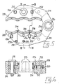
- the third illustrative supporting mechanism shown in Figures 5 to 7 is similar to the first illustrative mechanism except as hereinafter described.
- the mechanism comprises two opposed arms 212 and 214 mounted on a common pivot pin 216 for similar movement to the arms 12 and 14.
- the arms 214 and 216 consist of two plates instead of three and the triple, double and single supports consist of only one plate (250, 232 and 240 respectively) positioned between the two plates of the arms, so that the mould side portions 210 are each supported on only one plate.
- the triple support plate 250 is pivotal on a pivot pin 272 mounted on the arm 214 which is aligned with a centre line of a centre one of the three moulds. As there is only one triple support plate 250, a force apportioning member such as 62 is not necessary. The pivoting of the plate 250 about the pin 272 is limited by pins 254 mounted on the arm 214 which are loose fits in clearance holes 256 in the plate 250.
- the double support plate 232 is pivoted on a pivot pin 224 mounted on the arm 212 which is aligned with a line passing centrally between the centre mould and one of the other moulds (that nearest the pivot pin 216).
- the pivoting of the plate 232 is limited by a pin 228 mounted on the arm 212 which is a loose fit in a clearance hole 229 in the plate 232.
- the plate 232 does not directly support the mould side portions 210 but instead these are supported on two single support plates 274.
- Each plate 274 is arranged to support one of the mould side portions 210 supported by the double support 232.
- Each plate 274 is pivotally mounted on the double support 232 on a pin 276 and, when the arms 212 and 214 are in their mould closed positions, the pivots 276 of the single supports 274 are aligned with the centre-lines of their respective associated moulds.
- the pivoting of the single supports 274 is limited by a pin 278 mounted on the double support 232 and is a loose fit in two arcuate recesses 280, one of which is formed in each of the single supports 274.
- the single support plate 240 is pivoted on a pivot pin 226 mounted on the arm 212 which is aligned with a centre line of one of the moulds (that furthest from the pivot pin 216).
- the pivoting of the plate 240 is limited by a pin 230 which is mounted on the arm 212 and is a loose fit in a clearance hole in the plate 240.
- the pivots 226 and 276 enable the mould side portions 10 on the support plates 240 and 274 to move horizontally to their exact mating positions while the pivot 224 equalises the force between the centre mould and one of the other moulds and the pivot 272 equalises the force between the two non-centre moulds.
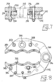
- the fourth illustrative supporting mechanism shown in Figure 8 is similar to the third illustrative mechanism except in the construction of its double support plate 332.
- the mechanism comprises two opposed arms 312 and 314 pivotal on a pin 316, the arms consisting of two plates while the triple, double and single supports consist of one plate (350, 332 and 340 respectively).
- the triple support plate 350 is pivotal on a pin 372 similar to the pin 272 to a limit defined by pins 354 similar to pins 254.
- the double support plate 332 is pivotal on a pin 324 mounted on the arm 312 to a limit set by a pin 328.
- the plate 332 does not have single support plates 274 mounted thereon but is itself arranged to support the mould side portions.
- the plate 332 is formed with an elongated slot 380 through which the pivot pin 324 passes.
- the slot 380 extends in a direction towards the single support plate 340 and normally thereto is a close fit on the pin 324.
- the slot 380 enables the double support plate 332 to shift its pivot point towards or away from the single support plate 340.
- the double support is arranged to slide to a limited extent (limited by the pin 328) relative to its pivot 324 in a direction normal to the side passing halfway between the centre mould and one of the other moulds.
- the single support plate 340 is pivoted on a pin 326 similar to the pin 226, the pivoting being limited by a pin 330 similar to the pin 230.
Landscapes
- Engineering & Computer Science (AREA)
- Chemical & Material Sciences (AREA)
- Manufacturing & Machinery (AREA)
- Materials Engineering (AREA)
- Organic Chemistry (AREA)
- Re-Forming, After-Treatment, Cutting And Transporting Of Glass Products (AREA)
- Moulds For Moulding Plastics Or The Like (AREA)
Applications Claiming Priority (2)
| Application Number | Priority Date | Filing Date | Title |
|---|---|---|---|
| GB878730249A GB8730249D0 (en) | 1987-12-29 | 1987-12-29 | Supporting mechanism for three moulds in glassware forming machine |
| GB8730249 | 1987-12-29 |
Publications (3)
| Publication Number | Publication Date |
|---|---|
| EP0323033A2 true EP0323033A2 (de) | 1989-07-05 |
| EP0323033A3 EP0323033A3 (en) | 1990-09-19 |
| EP0323033B1 EP0323033B1 (de) | 1992-12-30 |
Family
ID=10629132
Family Applications (1)
| Application Number | Title | Priority Date | Filing Date |
|---|---|---|---|
| EP88311274A Expired EP0323033B1 (de) | 1987-12-29 | 1988-11-29 | Tragevorrichtung für drei Matrizen in einer Maschine zum Herstellen von Glasgegenständen |
Country Status (5)
| Country | Link |
|---|---|
| US (1) | US4861365A (de) |
| EP (1) | EP0323033B1 (de) |
| JP (1) | JPH01203232A (de) |
| DE (1) | DE3877176T2 (de) |
| GB (1) | GB8730249D0 (de) |
Families Citing this family (7)
| Publication number | Priority date | Publication date | Assignee | Title |
|---|---|---|---|---|
| US5891209A (en) * | 1997-11-06 | 1999-04-06 | Emhart Glass S.A. | Mold opening and closing mechanism for an I. S. machine |
| US5830254A (en) * | 1997-11-06 | 1998-11-03 | Emhart Glass Machinery Investments Inc. | Mold opening and closing mechanism for an I.S. machine |
| US5902370A (en) * | 1997-11-06 | 1999-05-11 | Emhart Glass S.A. | Mold opening and closing mechanism for an I S machine |
| US6807828B2 (en) * | 2001-12-19 | 2004-10-26 | Emhart Glass S.A. | I.S. glass forming machine |
| US6807830B2 (en) * | 2001-12-19 | 2004-10-26 | Emhart Glass S.A. | I.S. glass forming machine |
| US6832494B2 (en) * | 2001-12-19 | 2004-12-21 | Emhart Glass S.A. | I.S. glass forming machine |
| US10081564B1 (en) * | 2014-05-15 | 2018-09-25 | Pyrotek, Inc. | Glass bottle forming machine |
Family Cites Families (4)
| Publication number | Priority date | Publication date | Assignee | Title |
|---|---|---|---|---|
| US3472639A (en) * | 1966-09-26 | 1969-10-14 | Owens Illinois Inc | Glass molding apparatus with mold element aligning means |
| US3607207A (en) * | 1969-02-18 | 1971-09-21 | Emhart Corp | Triple gob mold holder arm construction |
| US4486215A (en) * | 1983-05-26 | 1984-12-04 | Owens-Illinois, Inc. | Quadruple cavity glass mold operating apparatus |
| GB8618315D0 (en) * | 1986-07-26 | 1986-09-03 | Emhart Ind | Holding mould side portions in glassware forming machine |
-
1987
- 1987-12-29 GB GB878730249A patent/GB8730249D0/en active Pending
-
1988
- 1988-11-29 DE DE8888311274T patent/DE3877176T2/de not_active Expired - Fee Related
- 1988-11-29 EP EP88311274A patent/EP0323033B1/de not_active Expired
- 1988-12-06 US US07/280,768 patent/US4861365A/en not_active Expired - Fee Related
- 1988-12-26 JP JP63328789A patent/JPH01203232A/ja active Pending
Also Published As
| Publication number | Publication date |
|---|---|
| DE3877176T2 (de) | 1993-04-29 |
| US4861365A (en) | 1989-08-29 |
| EP0323033A3 (en) | 1990-09-19 |
| JPH01203232A (ja) | 1989-08-16 |
| EP0323033B1 (de) | 1992-12-30 |
| GB8730249D0 (en) | 1988-02-03 |
| DE3877176D1 (de) | 1993-02-11 |
Similar Documents
| Publication | Publication Date | Title |
|---|---|---|
| EP0323033B1 (de) | Tragevorrichtung für drei Matrizen in einer Maschine zum Herstellen von Glasgegenständen | |
| EP0345933B1 (de) | Glaswarenformmaschine | |
| EP0195599B1 (de) | Vorrichtung zum Öffnen und zum Schliessen von Matrizen in einer Maschine zum Herstellen von Glasgegenständen | |
| EP0323034B1 (de) | Tragevorrichtung für Matrizenrandteile in einer Maschine zum Herstellen von Glasgegenständen | |
| US4561875A (en) | Mould arrangement for a cyclicly operating glassware forming machine | |
| US4486215A (en) | Quadruple cavity glass mold operating apparatus | |
| US3607207A (en) | Triple gob mold holder arm construction | |
| US5298049A (en) | Trough system | |
| EP0255329A1 (de) | Vorrichtung zur Halterung der Seitenteile von Formen in einer Glaswarenformmaschine | |
| US4261724A (en) | Triple gob blowhead or baffle construction | |
| US3268322A (en) | Glass forming apparatus | |
| EP0156639B1 (de) | Formhalterung für eine Glaswaren-Formmaschine | |
| EP0210748B1 (de) | Bewegungsmechanismus zur Anwendung in einer Maschine zur Herstellung von Glasgegenständen vom Individualsektionstyp | |
| US4969945A (en) | Holder for the mold halves of an IS machine for making hollow glass articles | |
| EP0148572B1 (de) | Sektion einer Glaswarenformmaschine vom IS-Typ | |
| US4610713A (en) | Settle blow head and baffle arm attachment for glassware molding machine | |
| US3561941A (en) | Triple gob settle blowhead and baffle construction | |
| US2062522A (en) | Glass forming machine | |
| US1764166A (en) | Glassware-forming machine | |
| US6085552A (en) | Aligning fixture for mold opening and closing mechanism | |
| GB2123401A (en) | Method of cooling a mould | |
| GB2324298A (en) | Mould support assembly |
Legal Events
| Date | Code | Title | Description |
|---|---|---|---|
| PUAI | Public reference made under article 153(3) epc to a published international application that has entered the european phase |
Free format text: ORIGINAL CODE: 0009012 |
|
| AK | Designated contracting states |
Kind code of ref document: A2 Designated state(s): DE FR GB IT |
|
| RAP1 | Party data changed (applicant data changed or rights of an application transferred) |
Owner name: EMHART INDUSTRIES, INC. |
|
| PUAL | Search report despatched |
Free format text: ORIGINAL CODE: 0009013 |
|
| AK | Designated contracting states |
Kind code of ref document: A3 Designated state(s): DE FR GB IT |
|
| 17P | Request for examination filed |
Effective date: 19901012 |
|
| RAP1 | Party data changed (applicant data changed or rights of an application transferred) |
Owner name: EMHART GLASS MACHINERY INC., |
|
| RAP1 | Party data changed (applicant data changed or rights of an application transferred) |
Owner name: EMHART GLASS MACHINERY INVESTMENTS INC. |
|
| 17Q | First examination report despatched |
Effective date: 19920408 |
|
| GRAA | (expected) grant |
Free format text: ORIGINAL CODE: 0009210 |
|
| AK | Designated contracting states |
Kind code of ref document: B1 Designated state(s): DE FR GB IT |
|
| REF | Corresponds to: |
Ref document number: 3877176 Country of ref document: DE Date of ref document: 19930211 |
|
| ET | Fr: translation filed | ||
| ITF | It: translation for a ep patent filed | ||
| PLBE | No opposition filed within time limit |
Free format text: ORIGINAL CODE: 0009261 |
|
| STAA | Information on the status of an ep patent application or granted ep patent |
Free format text: STATUS: NO OPPOSITION FILED WITHIN TIME LIMIT |
|
| 26N | No opposition filed | ||
| PGFP | Annual fee paid to national office [announced via postgrant information from national office to epo] |
Ref country code: FR Payment date: 19941013 Year of fee payment: 7 |
|
| PGFP | Annual fee paid to national office [announced via postgrant information from national office to epo] |
Ref country code: GB Payment date: 19941018 Year of fee payment: 7 |
|
| PGFP | Annual fee paid to national office [announced via postgrant information from national office to epo] |
Ref country code: DE Payment date: 19941026 Year of fee payment: 7 |
|
| PG25 | Lapsed in a contracting state [announced via postgrant information from national office to epo] |
Ref country code: GB Effective date: 19951129 |
|
| GBPC | Gb: european patent ceased through non-payment of renewal fee |
Effective date: 19951129 |
|
| PG25 | Lapsed in a contracting state [announced via postgrant information from national office to epo] |
Ref country code: FR Effective date: 19960731 |
|
| PG25 | Lapsed in a contracting state [announced via postgrant information from national office to epo] |
Ref country code: DE Effective date: 19960801 |
|
| REG | Reference to a national code |
Ref country code: FR Ref legal event code: ST |
|
| PG25 | Lapsed in a contracting state [announced via postgrant information from national office to epo] |
Ref country code: IT Free format text: LAPSE BECAUSE OF NON-PAYMENT OF DUE FEES;WARNING: LAPSES OF ITALIAN PATENTS WITH EFFECTIVE DATE BEFORE 2007 MAY HAVE OCCURRED AT ANY TIME BEFORE 2007. THE CORRECT EFFECTIVE DATE MAY BE DIFFERENT FROM THE ONE RECORDED. Effective date: 20051129 |