EP0322294B2 - Verfahren zum Zusammenbau eines hydropneumatischen Druckspeichers - Google Patents
Verfahren zum Zusammenbau eines hydropneumatischen Druckspeichers Download PDFInfo
- Publication number
- EP0322294B2 EP0322294B2 EP19880403230 EP88403230A EP0322294B2 EP 0322294 B2 EP0322294 B2 EP 0322294B2 EP 19880403230 EP19880403230 EP 19880403230 EP 88403230 A EP88403230 A EP 88403230A EP 0322294 B2 EP0322294 B2 EP 0322294B2
- Authority
- EP
- European Patent Office
- Prior art keywords
- bowl
- retaining ring
- cover
- membrane
- mounting
- Prior art date
- Legal status (The legal status is an assumption and is not a legal conclusion. Google has not performed a legal analysis and makes no representation as to the accuracy of the status listed.)
- Expired - Lifetime
Links
Images

Classifications
-
- F—MECHANICAL ENGINEERING; LIGHTING; HEATING; WEAPONS; BLASTING
- F15—FLUID-PRESSURE ACTUATORS; HYDRAULICS OR PNEUMATICS IN GENERAL
- F15B—SYSTEMS ACTING BY MEANS OF FLUIDS IN GENERAL; FLUID-PRESSURE ACTUATORS, e.g. SERVOMOTORS; DETAILS OF FLUID-PRESSURE SYSTEMS, NOT OTHERWISE PROVIDED FOR
- F15B1/00—Installations or systems with accumulators; Supply reservoir or sump assemblies
- F15B1/02—Installations or systems with accumulators
- F15B1/04—Accumulators
- F15B1/08—Accumulators using a gas cushion; Gas charging devices; Indicators or floats therefor
- F15B1/10—Accumulators using a gas cushion; Gas charging devices; Indicators or floats therefor with flexible separating means
- F15B1/12—Accumulators using a gas cushion; Gas charging devices; Indicators or floats therefor with flexible separating means attached at their periphery
- F15B1/14—Accumulators using a gas cushion; Gas charging devices; Indicators or floats therefor with flexible separating means attached at their periphery by means of a rigid annular supporting member
-
- B—PERFORMING OPERATIONS; TRANSPORTING
- B60—VEHICLES IN GENERAL
- B60G—VEHICLE SUSPENSION ARRANGEMENTS
- B60G2206/00—Indexing codes related to the manufacturing of suspensions: constructional features, the materials used, procedures or tools
- B60G2206/01—Constructional features of suspension elements, e.g. arms, dampers, springs
- B60G2206/40—Constructional features of dampers and/or springs
- B60G2206/42—Springs
- B60G2206/422—Accumulators for hydropneumatic springs
- B60G2206/4222—Accumulators for hydropneumatic springs with a flexible separating wall; Membrane construction
-
- F—MECHANICAL ENGINEERING; LIGHTING; HEATING; WEAPONS; BLASTING
- F15—FLUID-PRESSURE ACTUATORS; HYDRAULICS OR PNEUMATICS IN GENERAL
- F15B—SYSTEMS ACTING BY MEANS OF FLUIDS IN GENERAL; FLUID-PRESSURE ACTUATORS, e.g. SERVOMOTORS; DETAILS OF FLUID-PRESSURE SYSTEMS, NOT OTHERWISE PROVIDED FOR
- F15B2201/00—Accumulators
- F15B2201/20—Accumulator cushioning means
- F15B2201/205—Accumulator cushioning means using gas
-
- F—MECHANICAL ENGINEERING; LIGHTING; HEATING; WEAPONS; BLASTING
- F15—FLUID-PRESSURE ACTUATORS; HYDRAULICS OR PNEUMATICS IN GENERAL
- F15B—SYSTEMS ACTING BY MEANS OF FLUIDS IN GENERAL; FLUID-PRESSURE ACTUATORS, e.g. SERVOMOTORS; DETAILS OF FLUID-PRESSURE SYSTEMS, NOT OTHERWISE PROVIDED FOR
- F15B2201/00—Accumulators
- F15B2201/30—Accumulator separating means
- F15B2201/315—Accumulator separating means having flexible separating means
- F15B2201/3151—Accumulator separating means having flexible separating means the flexible separating means being diaphragms or membranes
-
- F—MECHANICAL ENGINEERING; LIGHTING; HEATING; WEAPONS; BLASTING
- F15—FLUID-PRESSURE ACTUATORS; HYDRAULICS OR PNEUMATICS IN GENERAL
- F15B—SYSTEMS ACTING BY MEANS OF FLUIDS IN GENERAL; FLUID-PRESSURE ACTUATORS, e.g. SERVOMOTORS; DETAILS OF FLUID-PRESSURE SYSTEMS, NOT OTHERWISE PROVIDED FOR
- F15B2201/00—Accumulators
- F15B2201/30—Accumulator separating means
- F15B2201/315—Accumulator separating means having flexible separating means
- F15B2201/3156—Accumulator separating means having flexible separating means characterised by their attachment
-
- F—MECHANICAL ENGINEERING; LIGHTING; HEATING; WEAPONS; BLASTING
- F15—FLUID-PRESSURE ACTUATORS; HYDRAULICS OR PNEUMATICS IN GENERAL
- F15B—SYSTEMS ACTING BY MEANS OF FLUIDS IN GENERAL; FLUID-PRESSURE ACTUATORS, e.g. SERVOMOTORS; DETAILS OF FLUID-PRESSURE SYSTEMS, NOT OTHERWISE PROVIDED FOR
- F15B2201/00—Accumulators
- F15B2201/40—Constructional details of accumulators not otherwise provided for
- F15B2201/41—Liquid ports
- F15B2201/411—Liquid ports having valve means
-
- F—MECHANICAL ENGINEERING; LIGHTING; HEATING; WEAPONS; BLASTING
- F15—FLUID-PRESSURE ACTUATORS; HYDRAULICS OR PNEUMATICS IN GENERAL
- F15B—SYSTEMS ACTING BY MEANS OF FLUIDS IN GENERAL; FLUID-PRESSURE ACTUATORS, e.g. SERVOMOTORS; DETAILS OF FLUID-PRESSURE SYSTEMS, NOT OTHERWISE PROVIDED FOR
- F15B2201/00—Accumulators
- F15B2201/40—Constructional details of accumulators not otherwise provided for
- F15B2201/415—Gas ports
-
- F—MECHANICAL ENGINEERING; LIGHTING; HEATING; WEAPONS; BLASTING
- F15—FLUID-PRESSURE ACTUATORS; HYDRAULICS OR PNEUMATICS IN GENERAL
- F15B—SYSTEMS ACTING BY MEANS OF FLUIDS IN GENERAL; FLUID-PRESSURE ACTUATORS, e.g. SERVOMOTORS; DETAILS OF FLUID-PRESSURE SYSTEMS, NOT OTHERWISE PROVIDED FOR
- F15B2201/00—Accumulators
- F15B2201/40—Constructional details of accumulators not otherwise provided for
- F15B2201/43—Anti-extrusion means
- F15B2201/435—Anti-extrusion means being fixed to the separating means
Definitions
- the present invention relates to a method of mounting a hydropneumatic accumulator comprising an envelope consisting of a bowl and a lid linked by a weld bead, inside which is mounted in leaktight manner a membrane separating the envelope between a first chamber containing liquid and a second chamber containing gas, the membrane being mounted on a retaining ring by means of a bead engaged in a groove in the retaining ring which ensures the tightening of the membrane to the inside the envelope.
- Such an arrangement is not suitable for producing a weld bead without adding material.
- Document DE-A-3 207 754 describes a similar hydropneumatic accumulator in which the upper part of the bowl and the lower part of the cover each have a corresponding conical part of the retaining ring. In this accumulator, the weld bead is made with the addition of material.
- the present invention relates to a method of mounting a hydropneumatic accumulator which allows welding without addition of material, for example by laser beams.
- This process which is of the type mentioned in the preamble of claim 1, is characterized in that the retaining ring is placed inside the bowl so that its maximum diameter, resulting from the intersection of two reverse conical parts, is located to the right of the weld bead to be made and that, the cover being positioned on the conical surface of the retaining ring, there is a clearance between the contact surfaces of the bowl and of the cover so that the contact between the conical surfaces the retaining ring, the bowl and the cover is ensured by the plating of the contact surfaces bowl / cover for the welding, and that this welding is carried out without addition of material.
- This process allows the centering of the lid and the bowl on the retaining ring which is positively positioned between the bowl and the lid.
- the weld bead may have an interruption so as to bring the zones of contact between the conical surfaces of the retaining ring, the bowl and the cover to the atmosphere in order to ensure a better seal.
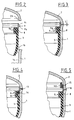
- the hydropneumatic accumulator comprises a bowl 1 and a cover 2 made of hot-rolled extra mild sheet steel, allowing deep drawing.
- a membrane 3 which separates the envelope into a first chamber 4 filled with liquid and a second chamber 5 filled with gas; this membrane is made of elastomer, for example UREPAN or EPICHLORYDRINE if the hydraulic fluid is mineral oil.
- the membrane 3 has a bead 8 which seals between the two chambers 4 and 5 by clamping between the cylindrical part 1 a of the lower bowl, and the cylindrical part 9 a of a retaining ring 9.
- a connector 10 for connection to the hydraulic circuit is laser welded to the lower bowl. After inflation with nitrogen, a filling orifice 11 formed in the cover 2 is closed by a plug 12 made of mild steel, for example a ball, electrically welded
- the part of the retaining ring 9 external to the membrane 3 has an external wall in double cone 9 b -9 c : the upper part of the bowl 1 and the lower part of the cover 2 have a conical surface 1 b or 2 b cooperating when the accumulator is mounted, with the double cone 9 b -9 c of the ring 9.
- the assembly is carried out by first fitting the bead 8 of the membrane into the retaining ring 9.
- the membrane 3 / ring 9 assembly is lowered into the bowl 1.
- the conical bearing 1 b using the bead 8 to engage in the cylindrical portion 1a of the bowl 1, until the contact of the cone 9 b on the common conical 1b.
- the sealing is then assured by the clamping of the bead 8 between the cylindrical portion 1a of the bowl and the cylindrical portion 9a of the holding rin e 9.
- the cover 2 is then set up by plating its conical bearing surface 2 b on the cone 9 c of the retaining ring.
- the dimension chains have been established in such a way that the retaining ring is always in contact with the conical surfaces of the bowl and the lid.
- the result between the edges of the bowl and the lid is a dimension L varying from 0 to a few tenths of a millimeter.
- the embodiment of Figure 5 does not require a sealing condition of the weld.
- the retaining ring 9 is extended at 9 d towards the cover 2 so as to be able to place a seal 15 between the ring and the cover.
- the weld bead is voluntarily interrupted over an area of a few millimeters, area indicated in 16, which puts the area of contact of the cones into the atmosphere. After filling the chamber 5, the internal nitrogen pressure pushes the seal 15 and the bead 8, without however extruding them since there is contact with metal parts, but these elements will always be in the sealing position as long as there will be an internal pressure.
Landscapes
- Engineering & Computer Science (AREA)
- Physics & Mathematics (AREA)
- Fluid Mechanics (AREA)
- Mechanical Engineering (AREA)
- General Engineering & Computer Science (AREA)
- Supply Devices, Intensifiers, Converters, And Telemotors (AREA)
Claims (4)
- Verfahren zum Zusammenbau eines hydropneumatischen Druckspeichers, der ein Gehäuse aufweist, das aus einer Schale (1) und einem Deckel (2) gebildet ist, die durch eine Schweißnaht (13) miteinander verbunden sind, und in dessen Inneren eine Membran (3) in abdichtender Weise eingebaut ist, die das Gehäuse in eine erste, mit Flüssigkeit gefüllte Kammer (4) und in eine zweite, mit Gas gefüllte Kammer (5) abtrennt und die an einem Haltering (9) mittels eines Wulstes (8) befestigt ist, der in eine Hohlkehle des Halterings eingreift, der die Einspannung der Membran (3) im Inneren des Gehäuses sicherstellt, wobei der obere Teil der Schale und der untere Teil des Deckels je einen konischen Bereich aufweisen, der mit einem entsprechenden konischen Bereich des Halterings zusammenwirkt, dadurch gekennzeichnet, daß der Haltering (9) im Inneren der Schale (1) so angeordnet wird, daß sich sein größter Durchmesser, der sich aus der Verschneidung von zwei entgegengesetzt gerichteten konischen Bereichen (9b und 9c) ergibt, gerade an der auszuführenden Schweißnaht befindet, und daß nach dem Positionieren des Deckels (2) auf dem konischen Bereich (9c) des Halterings (9) ein Spiel "L" zwischen den Kontaktflächen der Schale (1) und des Deckels (2) dergestalt vorhanden ist, daß der Kontakt zwischen den konischen Flächen des Halterings (9), der Schale (1) und des Deckels (2) durch das Aufeinanderbringen der Kontaktflächen Schale (1)/Deckel (2) für das Schweißen sichergestellt ist, und daß dieses Schweißen ohne Zusatz von Material erfolgt.
- Verfahren zum Zusammenbau des hydropneumatischen Druckspeichers nach Anspruch 1, dadurch gekennzeichnet, daß die Membran (3) in Höhe des Wulstes (8) an ihrer der Schale (1) zugewandten Seite eine Ausnehmung aufweist, in deren Inneren eine O-Ring-Dichtung (14) eingreift.
- Verfahren zum Zusammenbau des hydropneumatischen Druckspeichers nach Anspruch 1, dadurch gekennzeichnet, daß der Haltering (9) oberhalb des Bereiches (9c) eine Verlängerung (9d) aufweist, die zur Aufnahme einer O-Ring-Dichtung (15) dient.
- Verfahren zum Zusammenbau des hydropneumatischen Druckspeichers nach Anspruch 3, dadurch gekennzeichnet, daß die Schweißnaht (13) eine Unterbrechung (16) aufweist, so daß die Kontaktzonen zwischen den konischen Bereichen des Halterings, der Schale (1) und des Deckels (2) der Umgebungsluft ausgesetzt sind, um eine bessere Abdichtung sicherzustellen.
Applications Claiming Priority (2)
| Application Number | Priority Date | Filing Date | Title |
|---|---|---|---|
| FR8718332 | 1987-12-21 | ||
| FR8718332A FR2624926B1 (fr) | 1987-12-21 | 1987-12-21 | Accumulateur hydropneumatique |
Publications (3)
| Publication Number | Publication Date |
|---|---|
| EP0322294A1 EP0322294A1 (de) | 1989-06-28 |
| EP0322294B1 EP0322294B1 (de) | 1991-03-27 |
| EP0322294B2 true EP0322294B2 (de) | 1995-02-15 |
Family
ID=9358410
Family Applications (1)
| Application Number | Title | Priority Date | Filing Date |
|---|---|---|---|
| EP19880403230 Expired - Lifetime EP0322294B2 (de) | 1987-12-21 | 1988-12-19 | Verfahren zum Zusammenbau eines hydropneumatischen Druckspeichers |
Country Status (4)
| Country | Link |
|---|---|
| EP (1) | EP0322294B2 (de) |
| DE (1) | DE3862190D1 (de) |
| ES (1) | ES2021456T5 (de) |
| FR (1) | FR2624926B1 (de) |
Families Citing this family (2)
| Publication number | Priority date | Publication date | Assignee | Title |
|---|---|---|---|---|
| EP0437987A3 (en) * | 1990-01-19 | 1991-11-27 | Olaer Industries | Flexible composite separator for pressure accumulator, its method of manufacture, and an accumulator including such a separator |
| DE102021000139A1 (de) * | 2021-01-14 | 2022-07-14 | Hydac Technology Gmbh | Hydrospeicher |
Family Cites Families (3)
| Publication number | Priority date | Publication date | Assignee | Title |
|---|---|---|---|---|
| US2345124A (en) * | 1941-12-01 | 1944-03-28 | New York Air Brake Co | Accumulator |
| DE2325844C3 (de) * | 1973-05-22 | 1982-01-21 | Daimler-Benz Ag, 7000 Stuttgart | Hydropneumatischer Druckspeicher |
| DE2419557A1 (de) * | 1974-04-23 | 1975-11-06 | Sugimura | Speicher |
-
1987
- 1987-12-21 FR FR8718332A patent/FR2624926B1/fr not_active Expired - Fee Related
-
1988
- 1988-12-19 DE DE8888403230T patent/DE3862190D1/de not_active Expired - Lifetime
- 1988-12-19 ES ES88403230T patent/ES2021456T5/es not_active Expired - Lifetime
- 1988-12-19 EP EP19880403230 patent/EP0322294B2/de not_active Expired - Lifetime
Also Published As
| Publication number | Publication date |
|---|---|
| DE3862190D1 (de) | 1991-05-02 |
| EP0322294B1 (de) | 1991-03-27 |
| ES2021456T5 (es) | 1995-08-16 |
| FR2624926A1 (fr) | 1989-06-23 |
| FR2624926B1 (fr) | 1993-05-14 |
| EP0322294A1 (de) | 1989-06-28 |
| ES2021456B3 (es) | 1991-11-01 |
Similar Documents
| Publication | Publication Date | Title |
|---|---|---|
| EP0191703B1 (de) | Änderungen an hydraulischen Antischwingungslagern | |
| EP1535551B1 (de) | Dampfdruck-Kochtopf mit Sicherheitsvorrichtung für Überdruck, und Dichtung für solch einen Topf | |
| EP0122848B1 (de) | Verfahren zum Herstellen einer hydraulischen Verbindung | |
| EP0140171B1 (de) | Dichtung für Verbindungen von gusseisernen Rohren | |
| FR2513704A1 (fr) | Reservoir de pression economique | |
| EP3982014B1 (de) | Dichtungsfuge mit einer schürze | |
| EP0322294B2 (de) | Verfahren zum Zusammenbau eines hydropneumatischen Druckspeichers | |
| FR2754024A1 (fr) | Soufflet de transmission pour un vehicule automobile et son procede de remplacement | |
| EP0237770B1 (de) | Aufblasbare Dichtung, bei der die Anpressung durch Druckentlastung erfolgt | |
| FR2758379A1 (fr) | Cartouche d'implantation pour un raccord d'un tuyau destine a prendre place dans un logement | |
| FR2488662A1 (fr) | Dispositif reservoir de pression, notamment accumulateur de pression a vessie remplacable | |
| EP2932139A1 (de) | Dichtung für eine elektrische verbindung | |
| EP1565271A1 (de) | Abgabepumpe geeignet zum verschliessen eines behälterhalses und verpackung eines zu versprühenden produktes mit einer solchen abgabepumpe und einem behälter | |
| FR3072149A1 (fr) | Joint d'etancheite | |
| FR2530744A1 (fr) | Reservoir de pression tel qu'accumulateur de pression et son procede de fabrication | |
| EP3240650B1 (de) | Elektrohydraulische formvorrichtung | |
| EP2914883B1 (de) | Kostengünstige und hochleistungsfähige ringförmige statische metalldichtung für hohe drücke und grosse durchmesser | |
| CH638872A5 (fr) | Accumulateur de pression et son procede de fabrication. | |
| EP2182266B1 (de) | Dichtungssystem mit Dichtung für Rohrklemme mit Aufnahmemittel und Klemme | |
| FR2739668A1 (fr) | Dispositif perfectionne d'obturation a guide centreur lubrifie pour tube d'amortisseur hydraulique pressurise | |
| FR2494613A1 (fr) | Procede et dispositif d'assemblage non demontable de pieces tournantes, telles que des elements d'arbre | |
| EP0651197B1 (de) | Verfahren zum hermetischen Zusammenbauen einer Dichtung und eines Rohres und Zusammenbau einer solchen Dichtung mit einem Rohr | |
| FR2585780A3 (fr) | Composant de circuit pneumatique ou hydraulique, muni d'un agencement d'etancheite perfectionne, pour pressions de service relativement elevees | |
| FR2683887A1 (fr) | Raccord pour tubes resistant a la pression. | |
| FR2673263A1 (fr) | Ensemble formant joint pour raccordement souple entre deux elements. |
Legal Events
| Date | Code | Title | Description |
|---|---|---|---|
| PUAI | Public reference made under article 153(3) epc to a published international application that has entered the european phase |
Free format text: ORIGINAL CODE: 0009012 |
|
| AK | Designated contracting states |
Kind code of ref document: A1 Designated state(s): DE ES FR GB IT |
|
| 17P | Request for examination filed |
Effective date: 19890502 |
|
| 17Q | First examination report despatched |
Effective date: 19900725 |
|
| GRAA | (expected) grant |
Free format text: ORIGINAL CODE: 0009210 |
|
| AK | Designated contracting states |
Kind code of ref document: B1 Designated state(s): DE ES FR GB IT |
|
| REF | Corresponds to: |
Ref document number: 3862190 Country of ref document: DE Date of ref document: 19910502 |
|
| ITF | It: translation for a ep patent filed | ||
| GBT | Gb: translation of ep patent filed (gb section 77(6)(a)/1977) | ||
| PLBI | Opposition filed |
Free format text: ORIGINAL CODE: 0009260 |
|
| 26 | Opposition filed |
Opponent name: INTEGRAL HYDRAULIK & CO. Effective date: 19910724 |
|
| PLBI | Opposition filed |
Free format text: ORIGINAL CODE: 0009260 |
|
| 26 | Opposition filed |
Opponent name: HYDAC TECHNOLOGY GMBH Effective date: 19911211 Opponent name: INTEGRAL HYDRAULIK & CO. Effective date: 19910724 |
|
| PUAH | Patent maintained in amended form |
Free format text: ORIGINAL CODE: 0009272 |
|
| STAA | Information on the status of an ep patent application or granted ep patent |
Free format text: STATUS: PATENT MAINTAINED AS AMENDED |
|
| 27A | Patent maintained in amended form |
Effective date: 19950215 |
|
| AK | Designated contracting states |
Kind code of ref document: B2 Designated state(s): DE ES FR GB IT |
|
| GBTA | Gb: translation of amended ep patent filed (gb section 77(6)(b)/1977) |
Effective date: 19950215 |
|
| ITF | It: translation for a ep patent filed | ||
| REG | Reference to a national code |
Ref country code: ES Ref legal event code: DC2A Kind code of ref document: T5 Effective date: 19950816 |
|
| REG | Reference to a national code |
Ref country code: GB Ref legal event code: IF02 |
|
| PG25 | Lapsed in a contracting state [announced via postgrant information from national office to epo] |
Ref country code: FR Free format text: LAPSE BECAUSE OF NON-PAYMENT OF DUE FEES Effective date: 20040831 |
|
| REG | Reference to a national code |
Ref country code: FR Ref legal event code: ST |
|
| PGFP | Annual fee paid to national office [announced via postgrant information from national office to epo] |
Ref country code: FR Payment date: 20041027 Year of fee payment: 17 |
|
| REG | Reference to a national code |
Ref country code: GB Ref legal event code: 746 Effective date: 20070112 |
|
| PGFP | Annual fee paid to national office [announced via postgrant information from national office to epo] |
Ref country code: ES Payment date: 20071207 Year of fee payment: 20 |
|
| PGFP | Annual fee paid to national office [announced via postgrant information from national office to epo] |
Ref country code: IT Payment date: 20071212 Year of fee payment: 20 |
|
| PGFP | Annual fee paid to national office [announced via postgrant information from national office to epo] |
Ref country code: GB Payment date: 20071129 Year of fee payment: 20 |
|
| PGFP | Annual fee paid to national office [announced via postgrant information from national office to epo] |
Ref country code: DE Payment date: 20071129 Year of fee payment: 20 |
|
| REG | Reference to a national code |
Ref country code: GB Ref legal event code: PE20 Expiry date: 20081218 |
|
| REG | Reference to a national code |
Ref country code: ES Ref legal event code: FD2A Effective date: 20081220 |
|
| PG25 | Lapsed in a contracting state [announced via postgrant information from national office to epo] |
Ref country code: ES Free format text: LAPSE BECAUSE OF EXPIRATION OF PROTECTION Effective date: 20081220 |
|
| PG25 | Lapsed in a contracting state [announced via postgrant information from national office to epo] |
Ref country code: GB Free format text: LAPSE BECAUSE OF EXPIRATION OF PROTECTION Effective date: 20081218 |