EP0321745A2 - Photoionization detector for gas chromatography - Google Patents
Photoionization detector for gas chromatography Download PDFInfo
- Publication number
- EP0321745A2 EP0321745A2 EP88119926A EP88119926A EP0321745A2 EP 0321745 A2 EP0321745 A2 EP 0321745A2 EP 88119926 A EP88119926 A EP 88119926A EP 88119926 A EP88119926 A EP 88119926A EP 0321745 A2 EP0321745 A2 EP 0321745A2
- Authority
- EP
- European Patent Office
- Prior art keywords
- detector
- chamber
- lamp
- photoionization
- sweep gas
- Prior art date
- Legal status (The legal status is an assumption and is not a legal conclusion. Google has not performed a legal analysis and makes no representation as to the accuracy of the status listed.)
- Granted
Links
Images

Classifications
-
- G—PHYSICS
- G01—MEASURING; TESTING
- G01N—INVESTIGATING OR ANALYSING MATERIALS BY DETERMINING THEIR CHEMICAL OR PHYSICAL PROPERTIES
- G01N30/00—Investigating or analysing materials by separation into components using adsorption, absorption or similar phenomena or using ion-exchange, e.g. chromatography or field flow fractionation
- G01N30/02—Column chromatography
- G01N30/62—Detectors specially adapted therefor
- G01N30/64—Electrical detectors
-
- G—PHYSICS
- G01—MEASURING; TESTING
- G01N—INVESTIGATING OR ANALYSING MATERIALS BY DETERMINING THEIR CHEMICAL OR PHYSICAL PROPERTIES
- G01N27/00—Investigating or analysing materials by the use of electric, electrochemical, or magnetic means
- G01N27/62—Investigating or analysing materials by the use of electric, electrochemical, or magnetic means by investigating the ionisation of gases, e.g. aerosols; by investigating electric discharges, e.g. emission of cathode
- G01N27/64—Investigating or analysing materials by the use of electric, electrochemical, or magnetic means by investigating the ionisation of gases, e.g. aerosols; by investigating electric discharges, e.g. emission of cathode using wave or particle radiation to ionise a gas, e.g. in an ionisation chamber
- G01N27/66—Investigating or analysing materials by the use of electric, electrochemical, or magnetic means by investigating the ionisation of gases, e.g. aerosols; by investigating electric discharges, e.g. emission of cathode using wave or particle radiation to ionise a gas, e.g. in an ionisation chamber and measuring current or voltage
-
- G—PHYSICS
- G01—MEASURING; TESTING
- G01N—INVESTIGATING OR ANALYSING MATERIALS BY DETERMINING THEIR CHEMICAL OR PHYSICAL PROPERTIES
- G01N30/00—Investigating or analysing materials by separation into components using adsorption, absorption or similar phenomena or using ion-exchange, e.g. chromatography or field flow fractionation
- G01N30/02—Column chromatography
- G01N30/62—Detectors specially adapted therefor
- G01N30/64—Electrical detectors
- G01N2030/642—Electrical detectors photoionisation detectors
Definitions
- the present invention pertains to photoionization detectors useful in the field of gas chromatography.
- a special electrode arrangement for ion detection within a PID is the subject of U.S. Patent 4,013,913, awarded to Driscoll and Spaziani.
- An electrode arrangement is disclosed in this patent where an anode and cathode are positioned, with respect to the ionizing radiation, such that an annular configuration is defined with the anode directly exposed to the radiant energy and the cathode shielded from the energy source by either a metallic or an organic plastic material.
- Such an arrangement is said to produce low noise by minimizing the creation of unwanted photoelectrons from UV radiation striking the cathode.
- a PID usually includes a radiant energy source (usually high energy UV light of approximately 10 electron volts), an ionization chamber containing ion accelerator and collecting electrodes, and electronic circuitry for driving the photon source, amplifying the ion current and driving an output device.
- the sample to be detected is passed as a gas through the ionization chamber where it is exposed to the radiant energy and ionized.
- the ions formed are accelerated and collected by the electrode structures within the ionization chamber.
- the UV lamp window is in contact with the sample stream. Although this is desirable to minimize any unswept volume (dead volume), it allows the window to become fogged by nonvolatile components in the sample stream and by polymer products formed when certain GC eluates such as glycols are irradiated by the UV light. Such window coatings reduce the amount of light reaching the sample and cause a corresponding decrease in detector sensitivity. Detector performance will eventually deteriorate below that which is acceptable and then the lamp, which is quite expensive, must be replaced or the window cleaned if possible.
- a photoionization detector having a sweep gas inlet port adjacent the window to the radiation source, a vent, the detector adapted to receive a second detector mounted on its exterior without the need for lengthy, interconnection transfer tubes, and further comprising an automatic electronic control of the ionizing lamp.
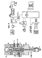
- FIGURE 1 A block diagram of the photoionization detector of the present invention is shown in FIGURE 1.
- the PID 10 consists of three main assemblies - the lamp power supply 11, an electrometer 12 and the detector proper (hereafter referred to as detector 13).
- detector 13 the detector proper
- this invention uses the electrometer supplied in the gas chromatograph, normally installed for operating a flame ionization detector, which is a very common detector available from all major chromatograph manufacturers.
- the novel features of this invention relate to the unique design elements of the detector and to the use of a "lamp saver" circuit located in the lamp power supply module.
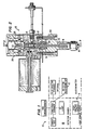
- FIGURES 2 and 3 show cross sectional view of the detector.
- the detector 13 is interfaced to the gas chromatograph column at 14.
- the sample stream is directed from the detector inlet through the glass-lined stainless steel transfer tube 15 and transfer port into the photoionization chamber 16 defined by the polarizing electrode 17, electrode spacer 18, collector electrode 19, ceramic insert 20, electrode biscuit 21, and lamp window 22.
- the transfer tube 15 rises through a mounting block 50 into the electrode biscuit 21 thrugh a tapered seal 51.
- the tapered seal has two tapered surfaces 52, 53 which pilot against matched tapered openings in the electrode biscuit and mounting block.
- the seal also accepts the polarizing electrode 17 in a recess 55.
- the sample stream is fluidically switched away from lamp window 22 by a sweep gas entering the photoionization chamber at sweep gas inlet port 23 and exits the chamber through exit transfer 24.
- Ions created from exposure of the sample within the ionization chamber 16 by UV lamp 25 contained within lamp biscuit 26 are accelerated by polarizing electrode 17 to collector electrode 19.
- Electrical connections to the electrometer input and polarizing voltage source are made via spring-loaded connectors 27 and 28.
- a novel design feature of the PID exit port 24, 29 is that it forms the female portion of a tube connection, which enables the reactor of an electrolytic conductivity detector to be directly interfaced to the PID without the use of a transfer tube as required by conventional designs.
- the electrode biscuit contains a vent exit port 30 connected to a solenoid controlled vent valve (not shown) via the vent exit tube 31, which allows unwanted sample components to be vented from the detector photoionization chamber 16 prior to the exit port 29 and entering the ELCD reactor when installed.
- venting mechanism into the PID is an additional novel feature of this invention not found in any other PID.
- This feature when combined with the sweep gas feature, using an ELCD reaction gas as the sweep gas (i.e. hydrogen or air, depending upon ELCD mode of operation) enables the PID to provide the venting and reaction gas introduction functions of the ELCD, normally performed by the detector base of the ELCD, in addition to the normal photoionization function of the PID.
- This allows the ELCD reactor to be interfaced directly to the PID, eliminating the need for ELCD detector base and the use of any transfer tubing to interface the two detectors. In this manner an unitized PID-ELCD detector system is formed, which requires the use of only one detector port.
- the "lamp saver" feature of the PID lamp supply is an additional novel feature of this invention.
- the operation of this feature can be understood with the aid of the simplified circuit schematic shown in FIGURE 4. Power to the Uv lamp is automatically removed after a user-selectable time has elapsed unless the timer is reset by a contact closure activated by a pushbutton on the supply module or a contact closure resident on and activated by another instrument such as a gas chromatograph or a purge-and-trap sample concentrator.
- the UV lamp will remain on during the entire time the detector is in use as long as the timer is set to a time longer than the chromatograph analysis time, because a ready signal (contact closure) will be generated by the chromatograph (or ancillary instrument) when it has completed a run and is ready to begin another. If not desired, the feature can be disabled by the "lamp saver" bypass switch.
- the "lamp saver" feature is not found on any other PID, and for this reason is a novel feature of this invention. This feature is useful in the operation of the PID, because many of the UV lamps used have a fairly short life of approximately 500 to 600 hours. As a result, if one forgets to turn off the PID lamp supply and it is left on at night or for a weekend, a considerable portion of the lamp's life will be wasted.
- FIGURE 5 The performance of the invention is shown in FIGURE 5.
- Response of the PID to a mixture of aromatic and chlorinated hydrocarbon compounds pertinent to United States Environmental Protection Agency methods 601 and 602 is shown in this FIGURE 5(a).
- the response of an ELCD connected in series and functioning with the PID as an unitized detector system is shown in FIGURE 5(b).
- the excellent response of the ELCD shows that no loss in peak integrity occurs by passing the sample through the PID.
Landscapes
- Chemical & Material Sciences (AREA)
- Health & Medical Sciences (AREA)
- General Health & Medical Sciences (AREA)
- Physics & Mathematics (AREA)
- Life Sciences & Earth Sciences (AREA)
- Analytical Chemistry (AREA)
- Biochemistry (AREA)
- General Physics & Mathematics (AREA)
- Immunology (AREA)
- Pathology (AREA)
- Chemical Kinetics & Catalysis (AREA)
- Electrochemistry (AREA)
- Toxicology (AREA)
- Other Investigation Or Analysis Of Materials By Electrical Means (AREA)
Abstract
Description
- The present invention pertains to photoionization detectors useful in the field of gas chromatography.
- The use of high energy photoionization for the detection of gas chromatograph (GC) eluates was first reported by J.E. Lovelock in Nature, Volume 188, Page 401, 1960. A variety of ionization techniques have been reviewed and compared also by Lovelock in Analytical Chemistry, Volume 33, page 163, 1961. The photoionization detector (PID) was first commercialized by J.N. Driscoll and F.F. Spaziani of HNU Systems, Inc., who have reviewed the development of the PID in Research/Development, Volume 27,
Page 50, 1976. Recently, various ionization techniques used in gas chromatograph detectors have been reviewed by P.L. Patterson in the Journal of Chromatographic Science,Volume 24, Page 466, 1986. - A special electrode arrangement for ion detection within a PID is the subject of U.S. Patent 4,013,913, awarded to Driscoll and Spaziani. An electrode arrangement is disclosed in this patent where an anode and cathode are positioned, with respect to the ionizing radiation, such that an annular configuration is defined with the anode directly exposed to the radiant energy and the cathode shielded from the energy source by either a metallic or an organic plastic material. Such an arrangement is said to produce low noise by minimizing the creation of unwanted photoelectrons from UV radiation striking the cathode.
- A PID usually includes a radiant energy source (usually high energy UV light of approximately 10 electron volts), an ionization chamber containing ion accelerator and collecting electrodes, and electronic circuitry for driving the photon source, amplifying the ion current and driving an output device. The sample to be detected is passed as a gas through the ionization chamber where it is exposed to the radiant energy and ionized. The ions formed are accelerated and collected by the electrode structures within the ionization chamber.
- Early PIDS had the ionization chamber pneumatically interconnected to the light source which consisted of an emission chamber driven by either a d.c. or r.f. discharge. Sealed light sources were later developed which did not have to be operated under vacuum, did not require the use of ultra-high purity gases and were not susceptible to a change in emission characteristics due to contamination of the discharge electrodes. These sources enabled reliable PIDS to be developed and allowed the PID to be commercialized.
- There are two primary problems related to present PID designs. First, the UV lamp window is in contact with the sample stream. Although this is desirable to minimize any unswept volume (dead volume), it allows the window to become fogged by nonvolatile components in the sample stream and by polymer products formed when certain GC eluates such as glycols are irradiated by the UV light. Such window coatings reduce the amount of light reaching the sample and cause a corresponding decrease in detector sensitivity. Detector performance will eventually deteriorate below that which is acceptable and then the lamp, which is quite expensive, must be replaced or the window cleaned if possible.
- It is important to minimize dead volume since it causes distortion of the gas chromatograph eluate profiles, which decreases the usefulness of the chromatographic system. Consequently, a PID design which prevents the sample stream from contacting the lamp window without the creation of any dead volume would be an obvious advance in PID technology.
- The second problem with present PID designs in the limitations that arise when a PID is connected in series with another detector such as an electrolytic conductivity detector (ELCD). In certain analyses it is analytically advantageous to connect the PID and ELCD so that the sample stream first passes through the PID and then through the ELCD. In this manner such sample components as aromatics and halogenated organics can be analyzed simultaneously with the PID and the ELCD, respectively. This enables all of the compounds of interest in such procedures as EPA methods 502.2, 601 and 602 to be analyzed using a single gas chromatographic run. It should be noted that recent EPA method 502.2 actually requires the use of a PID and an ELCD connected in series.
- Several present PID designs that are commercially available have adaptations which enable them to be serially interfaced to another detector, however, they are not truly engineered to be interfaced to the ELCD or any other detector. In the past, serially interfacing the PID and ELCD required the detectors to be mounted in their normal respective manners with a transfer tube connected from the PID exit port to the ELCD inlet port. The PID exit port was normally on the outside of the PID detector body and external to the GC oven, whereas the ELCD inlet was within the GC oven. Thus the transfer tube had to be heated and routed back into the oven to be connected to the ELCD inlet. This was usually done by routing the tube through the hole through which the PID detector inlet port protrudes into the GC oven or another drilled hole. This approach works, but suffers from the following limitations: (a) The transfer tube required to interface the PID to the ELCD is a potential source of leaks due to connections and breakage of the transfer tube (if the recommended, but fragile, materials such as fused silica are used); (b) Sensitive materials can be decomposed by any reactive surfaces of the transfer tube; (c) The integrity of the peak elution profiles can be deteriorated by cold spots and unswept volume in the transfer tube and fittings; and (d) Both detector ports of 2-port chromatographs are required for mounting the PID and ELCD detectors, precluding the use of a third detector.
- It is an object of the present invention to provide an improved photoionization detector which is adapted to the analysis of samples containing components of low volatility or components that can polymerize.
- It is another object of the present invention to provide an improved photoionization detector which is adapted to be connected serially with another detector such as an ELCD.
- It is yet another object of the present invention to provide an improved photoionization detector which is adapted to extend the lifetime of the UV lamp associated with the detector.
- It is a further object of the present invention to provide a detector chamber which may be vented.
- It is an additional object of the present invention to provide an automatic electronic control to the ionizing lamp which regulates power to the lamp for the purpose of extending lamp life.
- These and other objects are met by providing a photoionization detector having a sweep gas inlet port adjacent the window to the radiation source, a vent, the detector adapted to receive a second detector mounted on its exterior without the need for lengthy, interconnection transfer tubes, and further comprising an automatic electronic control of the ionizing lamp.
-
- FIGURE 1 is a schematic diagram of a system for gas chromatography utilizing the features of the present invention.
- FIGURE 2 is a cross-sectional view of the photoionization detector of the present invention.
- FIGURE 3 is a cross-sectional view, taken through lines 3-3 of FIGURE 2, of the photoionization detector of the present invention.
- FIGURE 4 is a schematic diagram of the lamp voltage control feature of the present invention.
- FIGURES 5(a) and 5(b) are representations of detector performance, wherein the features of the present invention are utilized.
- A block diagram of the photoionization detector of the present invention is shown in FIGURE 1. As can be seen by the dashed line divisions in this figure, the
PID 10 consists of three main assemblies - thelamp power supply 11, anelectrometer 12 and the detector proper (hereafter referred to as detector 13). As in the design of certain other PIDS, this invention uses the electrometer supplied in the gas chromatograph, normally installed for operating a flame ionization detector, which is a very common detector available from all major chromatograph manufacturers. The novel features of this invention relate to the unique design elements of the detector and to the use of a "lamp saver" circuit located in the lamp power supply module. - FIGURES 2 and 3 show cross sectional view of the detector. With reference to FIGURE 2, the
detector 13 is interfaced to the gas chromatograph column at 14. The sample stream is directed from the detector inlet through the glass-lined stainlesssteel transfer tube 15 and transfer port into thephotoionization chamber 16 defined by the polarizingelectrode 17,electrode spacer 18,collector electrode 19,ceramic insert 20,electrode biscuit 21, andlamp window 22. Thetransfer tube 15 rises through amounting block 50 into theelectrode biscuit 21 thrugh atapered seal 51. The tapered seal has twotapered surfaces electrode 17 in arecess 55. - With reference to FIGURE 3, the sample stream, is fluidically switched away from
lamp window 22 by a sweep gas entering the photoionization chamber at sweep gas inlet port 23 and exits the chamber throughexit transfer 24. - Ions created from exposure of the sample within the
ionization chamber 16 byUV lamp 25 contained withinlamp biscuit 26 are accelerated by polarizingelectrode 17 tocollector electrode 19. Electrical connections to the electrometer input and polarizing voltage source (contained within the electrometer's circuitry) are made via spring-loadedconnectors 27 and 28. - With reference again to FIGURE 2, a novel design feature of the
PID exit port 24, 29 is that it forms the female portion of a tube connection, which enables the reactor of an electrolytic conductivity detector to be directly interfaced to the PID without the use of a transfer tube as required by conventional designs. The electrode biscuit contains avent exit port 30 connected to a solenoid controlled vent valve (not shown) via thevent exit tube 31, which allows unwanted sample components to be vented from thedetector photoionization chamber 16 prior to the exit port 29 and entering the ELCD reactor when installed. - The incorporation of a venting mechanism into the PID is an additional novel feature of this invention not found in any other PID. This feature when combined with the sweep gas feature, using an ELCD reaction gas as the sweep gas (i.e. hydrogen or air, depending upon ELCD mode of operation) enables the PID to provide the venting and reaction gas introduction functions of the ELCD, normally performed by the detector base of the ELCD, in addition to the normal photoionization function of the PID. This allows the ELCD reactor to be interfaced directly to the PID, eliminating the need for ELCD detector base and the use of any transfer tubing to interface the two detectors. In this manner an unitized PID-ELCD detector system is formed, which requires the use of only one detector port.
- The "lamp saver" feature of the PID lamp supply is an additional novel feature of this invention. The operation of this feature can be understood with the aid of the simplified circuit schematic shown in FIGURE 4. Power to the Uv lamp is automatically removed after a user-selectable time has elapsed unless the timer is reset by a contact closure activated by a pushbutton on the supply module or a contact closure resident on and activated by another instrument such as a gas chromatograph or a purge-and-trap sample concentrator. In this manner, power to the UV lamp will remain on during the entire time the detector is in use as long as the timer is set to a time longer than the chromatograph analysis time, because a ready signal (contact closure) will be generated by the chromatograph (or ancillary instrument) when it has completed a run and is ready to begin another. If not desired, the feature can be disabled by the "lamp saver" bypass switch.
- The "lamp saver" feature is not found on any other PID, and for this reason is a novel feature of this invention. This feature is useful in the operation of the PID, because many of the UV lamps used have a fairly short life of approximately 500 to 600 hours. As a result, if one forgets to turn off the PID lamp supply and it is left on at night or for a weekend, a considerable portion of the lamp's life will be wasted.
- The performance of the invention is shown in FIGURE 5. Response of the PID to a mixture of aromatic and chlorinated hydrocarbon compounds pertinent to United States Environmental Protection Agency methods 601 and 602 is shown in this FIGURE 5(a). The response of an ELCD connected in series and functioning with the PID as an unitized detector system is shown in FIGURE 5(b). The excellent response of the ELCD shows that no loss in peak integrity occurs by passing the sample through the PID. Thus these novel design features can be seen to constitute definite analytical advantages. While we have described above the principles of the invention in terms of specific equipment and methods, it is to be understood that this description is made only by way of example and not as a limitation to be scope of the invention as set forth in the accompanying claims.
Claims (24)
a photoionization chamber;
the chamber having a cylindrical polarizing electrode disposed therein, and a cylindrical collector electrode between the polarizing electrode and the lamp window, the collector electrode co-axial to the polarizing electrode.
the ultra-violet lamp cooperates with a lamp saver.
an exit transfer is located between the lamp window and the vent exit.
a sweep gas inlet port is located between the exit transfer and the lamp window.
a photoionization chamber;
the chamber having a polarizing electrode;
a collector electrode;
and a sweep gas inlet port located between the electrodes and the lamp window.
the ultra-violet lamp is operatively controlled by a lamp saver means for prolonging lamp life.
the chamber further comprises an exit transfer aperture, the sweep gas inlet port located between the exit transfer aperture and the lamp window.
the chamber further comprises an insert, the insert having a central bore, the insert located between the lamp window and the electrodes, the insert adapted to direct the flow of sweep gas into proximity with the lamp window.
a photoionization detector having a lamp window and a photoionization chamber, the chamber having a sweep gas inlet port and a flow of sweep gas;
the sweep gas adapted to inhibit contact of a sample analyte with the lamp window.
the photoionization detector further comprises an exit transfer port;
the exit transfer port adapted to receive another detector;
the detector adapted to a flow of sweep gas from the sweep gas inlet port, through the exit transfer port.
the detector further comprises a threaded female aperture;
the threaded aperture forming an extension of the exit transfer port, the aperture adapted to receive a male threaded portion of a reactor.
the detector further comprises an insert within the chamber, the insert having a central bore, the exterior surface of the insert located adjacent the sweep gas inlet port.
analyte gases are introduced into a photoionization chamber, the chamber having an inlet, an exit and a vent;
analyte gases are removed from the photoionization chamber, through the vent.
further removal of analyte gases, from the chamber, occurs through the exit.
sweep gas is introduced into the chamber, and;
sweep gas and analyte gases are removed from the chamber, through the vent.
a vent, the vent located between the sample intake and sample exit of the chamber, the vent adapted to route the flow of gas in the chamber away from the sample exit and the window.
the chamber further comprises a sweep gas inlet, the inlet adjacent the window.
removing the sweep gas from the chamber so as to inhibit contact of analyte with the lamp window.
the method of chromatography further comprises a second analytical instrument;
the sweep gas is introduced from the photoionization detector into the second instrument and;
the sweep gas is utilized as a necessary reagent by the second instrument.
the second instrument is the reactor of an electrolyte conductivity detector.
a mounting block having a tapered opening;
an electrode biscuit having a tapered opening;
and
a tapered seal having two tapered surfaces, the seal adapted to engage both the electrode biscuit and mounting block, lying partially within each tapered opening.
the seal further comprises a recess adapted to receive an electrode.
the seal further comprises a central bore, the bore providing a clearance for a transfer tube.
Applications Claiming Priority (2)
| Application Number | Priority Date | Filing Date | Title |
|---|---|---|---|
| US128644 | 1987-12-04 | ||
| US07/128,644 US4804846A (en) | 1987-12-04 | 1987-12-04 | Photoionization detector for gas chromatography |
Publications (3)
| Publication Number | Publication Date |
|---|---|
| EP0321745A2 true EP0321745A2 (en) | 1989-06-28 |
| EP0321745A3 EP0321745A3 (en) | 1991-01-16 |
| EP0321745B1 EP0321745B1 (en) | 1995-04-12 |
Family
ID=22436304
Family Applications (1)
| Application Number | Title | Priority Date | Filing Date |
|---|---|---|---|
| EP88119926A Expired - Lifetime EP0321745B1 (en) | 1987-12-04 | 1988-11-30 | Photoionization detector for gas chromatography |
Country Status (4)
| Country | Link |
|---|---|
| US (1) | US4804846A (en) |
| EP (1) | EP0321745B1 (en) |
| JP (1) | JPH0758282B2 (en) |
| DE (1) | DE3853575T2 (en) |
Cited By (1)
| Publication number | Priority date | Publication date | Assignee | Title |
|---|---|---|---|---|
| WO1996002834A1 (en) * | 1994-07-15 | 1996-02-01 | Fisons Instruments S.P.A. | Photoionization detector and process |
Families Citing this family (18)
| Publication number | Priority date | Publication date | Assignee | Title |
|---|---|---|---|---|
| US5116764A (en) * | 1988-07-26 | 1992-05-26 | Raymond Annino | Dual-column, dual-detector gas detector and analyzer |
| US5206594A (en) * | 1990-05-11 | 1993-04-27 | Mine Safety Appliances Company | Apparatus and process for improved photoionization and detection |
| US5194814A (en) * | 1991-05-22 | 1993-03-16 | Tremetrics, Inc. | Electrolytic conductivity detector |
| US5289003A (en) * | 1992-05-29 | 1994-02-22 | The United States Of America As Represented By The Secretary Of The Department Of Health And Human Services | Probe for thermospray mass spectrometry |
| US5578271A (en) * | 1995-03-01 | 1996-11-26 | O.I. Corporation | Tandem photoionization detector and halogen specific detector |
| US6225633B1 (en) | 1998-10-22 | 2001-05-01 | Rae Systems, Inc. | Photo-ionization detector for volatile gas measurement and a method for self-cleaning the same |
| US7109476B2 (en) | 1999-02-09 | 2006-09-19 | Syagen Technology | Multiple ion sources involving atmospheric pressure photoionization |
| US6630664B1 (en) * | 1999-02-09 | 2003-10-07 | Syagen Technology | Atmospheric pressure photoionizer for mass spectrometry |
| US7119342B2 (en) * | 1999-02-09 | 2006-10-10 | Syagen Technology | Interfaces for a photoionization mass spectrometer |
| CA2386832C (en) | 1999-10-29 | 2009-09-29 | Mds Inc. | Atmospheric pressure photoionization (appi): a new ionization method for liquid chromatography-mass spectrometry |
| US6734435B2 (en) | 2001-05-29 | 2004-05-11 | Rae Systems, Inc. | Photo-ionization detector and method for continuous operation and real-time self-cleaning |
| DE60126264T2 (en) * | 2001-07-24 | 2007-11-22 | Schlumberger Technology B.V. | Heliumionisierungsdetektor |
| JP2003098153A (en) * | 2001-09-27 | 2003-04-03 | Yokogawa Electric Corp | Photoionization detector |
| KR100488871B1 (en) * | 2002-10-26 | 2005-05-11 | (주)백년기술 | Multichannel Photoionization Detector Using Multiphotoionization |
| US8922219B2 (en) | 2010-11-30 | 2014-12-30 | General Electric Company | Photo-ionization detectors and associated methods thereof |
| RU2523765C1 (en) * | 2012-12-24 | 2014-07-20 | Федеральное государственное бюджетное образовательное учреждение высшего профессионального образования "Тверской государственный технический университет" | Photo-ionisation detector for gas analysers |
| WO2018112733A1 (en) * | 2016-12-20 | 2018-06-28 | Honeywell International Inc. | Shielding for electrodes in photoionization detector |
| RU174543U1 (en) * | 2017-04-17 | 2017-10-19 | Федеральное государственное бюджетное образовательное учреждение высшего образования "Тверской государственный технический университет" | Photoionization gas detector |
Citations (12)
| Publication number | Priority date | Publication date | Assignee | Title |
|---|---|---|---|---|
| GB989614A (en) * | 1960-09-16 | 1965-04-22 | Nat Res Dev | Improvements in or relating to the measurement of gas or vapour concentrations |
| US3238367A (en) * | 1963-02-20 | 1966-03-01 | Beckman Instruments Inc | Device for the analysis of a fluent material by bombarding the same with photoelectrons |
| US3446964A (en) * | 1966-02-24 | 1969-05-27 | Beckman Instruments Inc | Method of suppressing photoionization of a gas sample in an electron capture detector |
| US3933432A (en) * | 1974-10-29 | 1976-01-20 | Hnu Systems Inc. | Photoionization |
| US4013913A (en) * | 1976-01-19 | 1977-03-22 | Hnu Systems Inc. | Ion detection electrode arrangement |
| US4202666A (en) * | 1978-02-24 | 1980-05-13 | Tracor, Inc. | Method and apparatus for preventing the destruction of an alkali source of a nitrogen-phosphorous detector |
| EP0015495A1 (en) * | 1979-02-27 | 1980-09-17 | Hewlett-Packard Company | Electron capture detector |
| US4266196A (en) * | 1978-03-31 | 1981-05-05 | Hitachi, Ltd. | Gas detecting means utilizing electric discharge |
| EP0184892A1 (en) * | 1984-12-14 | 1986-06-18 | The Perkin-Elmer Corporation | Ionization detector for gas chromatography and method therefor |
| GB2183897A (en) * | 1985-10-30 | 1987-06-10 | Perkin Elmer Corp | Ionization detectors for gas chromatography |
| DD248880A1 (en) * | 1986-05-05 | 1987-08-19 | Adw Ddr | DETECTOR FOR DETECTING GAS CHROMATOGRAPHIC ISOLATED SUBSTANCES |
| US4792396A (en) * | 1987-11-03 | 1988-12-20 | Rheodyne Incorporated | Multi-size injector port system |
Family Cites Families (7)
| Publication number | Priority date | Publication date | Assignee | Title |
|---|---|---|---|---|
| JPS4219671Y1 (en) * | 1964-02-15 | 1967-11-14 | ||
| GB1473389A (en) * | 1973-05-09 | 1977-05-11 | Dexploitation Des Brevets Ocla | Pipe couplings |
| JPS5522741B2 (en) * | 1975-01-16 | 1980-06-18 | ||
| US4063156A (en) * | 1976-02-27 | 1977-12-13 | Varian Associates, Inc. | Assymetric cylinder electron capture detector |
| SU960617A1 (en) * | 1980-12-29 | 1982-09-23 | Всесоюзный Научно-Исследовательский И Проектно-Конструкторский Институт Комплексной Автоматизации Нефтяной И Газовой Промышленности | Ionization method of analysis |
| JPS5938561B2 (en) * | 1981-08-17 | 1984-09-18 | 日本電信電話株式会社 | Sealed optical fiber core movement prevention device |
| SU1173292A1 (en) * | 1984-02-28 | 1985-08-15 | Всесоюзный научно-исследовательский и конструкторский институт хроматографии | Method of ionization detection of gas admixtures |
-
1987
- 1987-12-04 US US07/128,644 patent/US4804846A/en not_active Expired - Lifetime
-
1988
- 1988-11-30 DE DE3853575T patent/DE3853575T2/en not_active Expired - Fee Related
- 1988-11-30 EP EP88119926A patent/EP0321745B1/en not_active Expired - Lifetime
- 1988-12-02 JP JP63304249A patent/JPH0758282B2/en not_active Expired - Lifetime
Patent Citations (12)
| Publication number | Priority date | Publication date | Assignee | Title |
|---|---|---|---|---|
| GB989614A (en) * | 1960-09-16 | 1965-04-22 | Nat Res Dev | Improvements in or relating to the measurement of gas or vapour concentrations |
| US3238367A (en) * | 1963-02-20 | 1966-03-01 | Beckman Instruments Inc | Device for the analysis of a fluent material by bombarding the same with photoelectrons |
| US3446964A (en) * | 1966-02-24 | 1969-05-27 | Beckman Instruments Inc | Method of suppressing photoionization of a gas sample in an electron capture detector |
| US3933432A (en) * | 1974-10-29 | 1976-01-20 | Hnu Systems Inc. | Photoionization |
| US4013913A (en) * | 1976-01-19 | 1977-03-22 | Hnu Systems Inc. | Ion detection electrode arrangement |
| US4202666A (en) * | 1978-02-24 | 1980-05-13 | Tracor, Inc. | Method and apparatus for preventing the destruction of an alkali source of a nitrogen-phosphorous detector |
| US4266196A (en) * | 1978-03-31 | 1981-05-05 | Hitachi, Ltd. | Gas detecting means utilizing electric discharge |
| EP0015495A1 (en) * | 1979-02-27 | 1980-09-17 | Hewlett-Packard Company | Electron capture detector |
| EP0184892A1 (en) * | 1984-12-14 | 1986-06-18 | The Perkin-Elmer Corporation | Ionization detector for gas chromatography and method therefor |
| GB2183897A (en) * | 1985-10-30 | 1987-06-10 | Perkin Elmer Corp | Ionization detectors for gas chromatography |
| DD248880A1 (en) * | 1986-05-05 | 1987-08-19 | Adw Ddr | DETECTOR FOR DETECTING GAS CHROMATOGRAPHIC ISOLATED SUBSTANCES |
| US4792396A (en) * | 1987-11-03 | 1988-12-20 | Rheodyne Incorporated | Multi-size injector port system |
Non-Patent Citations (2)
| Title |
|---|
| ALL-UNION CHROMATOGRAPHY RESEARCH INSTITUTE, vol. 52, no. 11, November 1986, pages 5-7, Plenum Publishing Corp.; S.S. VASHCHUN et al.: "Sealed photoionization detector for gas-chromatographic analysis of traces of organic substances in air", Figure 1; page 982, paragraph 4. * |
| JOURNAL OF HIGH RESOLUTION CHROMATOGRAPHY, vol. 2, no. 5, May 1979, pages 243-245; F. POY: "A new approach to the simultaneous multidetection technique with electron capture and flame ionisation in series", Figure 1; page 243, column 1, paragraph 5 - column 2, paragraph 1. * |
Cited By (1)
| Publication number | Priority date | Publication date | Assignee | Title |
|---|---|---|---|---|
| WO1996002834A1 (en) * | 1994-07-15 | 1996-02-01 | Fisons Instruments S.P.A. | Photoionization detector and process |
Also Published As
| Publication number | Publication date |
|---|---|
| EP0321745A3 (en) | 1991-01-16 |
| JPH0758282B2 (en) | 1995-06-21 |
| JPH01301160A (en) | 1989-12-05 |
| EP0321745B1 (en) | 1995-04-12 |
| DE3853575T2 (en) | 1995-08-24 |
| US4804846A (en) | 1989-02-14 |
| DE3853575D1 (en) | 1995-05-18 |
Similar Documents
| Publication | Publication Date | Title |
|---|---|---|
| US4804846A (en) | Photoionization detector for gas chromatography | |
| US4708782A (en) | Chromatography column-electrophoresis system | |
| US4849628A (en) | Atmospheric sampling glow discharge ionization source | |
| EP0260635B1 (en) | Electrophoresis-mass spectrometry probe | |
| EP1733220B1 (en) | Photoionization detector | |
| US6437327B2 (en) | Mass spectrometry of solution and apparatus therefor | |
| US5968837A (en) | Photo-ionization ion mobility spectrometry | |
| CA1158891A (en) | Selective photoionization gas chromatograph detector system | |
| JPH04313050A (en) | Glow discharge spectrometer and glow discharge spectrochemical analysis method | |
| JP2009531652A (en) | Methods and apparatus for concentration and fractionation of analytes for chemical analysis | |
| US4304997A (en) | Electron capture detector with thermionic emission electron source | |
| CA2079800A1 (en) | Gas chromatograph-mass spectrometer (gc/ms) system for quantitative analysis of reactive chemical compounds | |
| US4740695A (en) | Ionization detectors for gas chromatography | |
| US5578271A (en) | Tandem photoionization detector and halogen specific detector | |
| CN112133623A (en) | VOCs (volatile organic compounds) navigation monitoring device | |
| US4264817A (en) | Coaxial electron capture detector with thermionic emission electron source | |
| EP0292974B1 (en) | Atmospheric sampling glow discharge ionization source | |
| CN209856440U (en) | Three-way switching valve applied to gas chromatography mass spectrometer for connecting thermal desorption | |
| US6107805A (en) | Extended detection zone in an ionization detector | |
| EP0831325B1 (en) | Method and apparatus for ion discrimination in an electron capture detector | |
| EP0387041A1 (en) | Nitrogen specific detector | |
| SU1444659A1 (en) | Photoionization detector for capillar gas chromatography | |
| SU1312480A1 (en) | Photoionization detector | |
| RU36889U1 (en) | LIQUID SAMPLE PREPARATION DEVICE FOR ISOTOPIC ANALYSIS OF HYDROGEN | |
| Chiu et al. | Chromatographic separation and identification of PCDD/PCDF isomers by CI and EI mass spectrometry |
Legal Events
| Date | Code | Title | Description |
|---|---|---|---|
| PUAI | Public reference made under article 153(3) epc to a published international application that has entered the european phase |
Free format text: ORIGINAL CODE: 0009012 |
|
| AK | Designated contracting states |
Kind code of ref document: A2 Designated state(s): AT BE CH DE ES FR GB GR IT LI LU NL SE |
|
| RBV | Designated contracting states (corrected) |
Designated state(s): BE DE FR GB NL |
|
| RIN1 | Information on inventor provided before grant (corrected) |
Inventor name: WILLIAMS, KARL M. Inventor name: HALL, RANDALL, C. |
|
| RHK1 | Main classification (correction) |
Ipc: G01N 30/64 |
|
| PUAL | Search report despatched |
Free format text: ORIGINAL CODE: 0009013 |
|
| AK | Designated contracting states |
Kind code of ref document: A3 Designated state(s): AT BE CH DE ES FR GB GR IT LI LU NL SE |
|
| 17P | Request for examination filed |
Effective date: 19910107 |
|
| 17Q | First examination report despatched |
Effective date: 19921027 |
|
| GRAA | (expected) grant |
Free format text: ORIGINAL CODE: 0009210 |
|
| AK | Designated contracting states |
Kind code of ref document: B1 Designated state(s): BE DE FR GB NL |
|
| REF | Corresponds to: |
Ref document number: 3853575 Country of ref document: DE Date of ref document: 19950518 |
|
| ET | Fr: translation filed | ||
| PLBE | No opposition filed within time limit |
Free format text: ORIGINAL CODE: 0009261 |
|
| STAA | Information on the status of an ep patent application or granted ep patent |
Free format text: STATUS: NO OPPOSITION FILED WITHIN TIME LIMIT |
|
| 26N | No opposition filed | ||
| PGFP | Annual fee paid to national office [announced via postgrant information from national office to epo] |
Ref country code: FR Payment date: 19991109 Year of fee payment: 12 |
|
| PGFP | Annual fee paid to national office [announced via postgrant information from national office to epo] |
Ref country code: GB Payment date: 19991124 Year of fee payment: 12 |
|
| PGFP | Annual fee paid to national office [announced via postgrant information from national office to epo] |
Ref country code: NL Payment date: 19991130 Year of fee payment: 12 |
|
| PG25 | Lapsed in a contracting state [announced via postgrant information from national office to epo] |
Ref country code: GB Free format text: LAPSE BECAUSE OF NON-PAYMENT OF DUE FEES Effective date: 20001130 |
|
| PG25 | Lapsed in a contracting state [announced via postgrant information from national office to epo] |
Ref country code: NL Free format text: LAPSE BECAUSE OF NON-PAYMENT OF DUE FEES Effective date: 20010601 |
|
| GBPC | Gb: european patent ceased through non-payment of renewal fee |
Effective date: 20001130 |
|
| PG25 | Lapsed in a contracting state [announced via postgrant information from national office to epo] |
Ref country code: FR Free format text: LAPSE BECAUSE OF NON-PAYMENT OF DUE FEES Effective date: 20010731 |
|
| NLV4 | Nl: lapsed or anulled due to non-payment of the annual fee |
Effective date: 20010601 |
|
| REG | Reference to a national code |
Ref country code: FR Ref legal event code: ST |
|
| PGFP | Annual fee paid to national office [announced via postgrant information from national office to epo] |
Ref country code: DE Payment date: 20041130 Year of fee payment: 17 Ref country code: BE Payment date: 20041130 Year of fee payment: 17 |
|
| PG25 | Lapsed in a contracting state [announced via postgrant information from national office to epo] |
Ref country code: BE Free format text: LAPSE BECAUSE OF NON-PAYMENT OF DUE FEES Effective date: 20051130 |
|
| PG25 | Lapsed in a contracting state [announced via postgrant information from national office to epo] |
Ref country code: DE Free format text: LAPSE BECAUSE OF NON-PAYMENT OF DUE FEES Effective date: 20060601 |
|
| BERE | Be: lapsed |
Owner name: *O.I. CORP. Effective date: 20051130 |