EP0184892A1 - Ionization detector for gas chromatography and method therefor - Google Patents
Ionization detector for gas chromatography and method therefor Download PDFInfo
- Publication number
- EP0184892A1 EP0184892A1 EP85305196A EP85305196A EP0184892A1 EP 0184892 A1 EP0184892 A1 EP 0184892A1 EP 85305196 A EP85305196 A EP 85305196A EP 85305196 A EP85305196 A EP 85305196A EP 0184892 A1 EP0184892 A1 EP 0184892A1
- Authority
- EP
- European Patent Office
- Prior art keywords
- gas
- chamber
- electrons
- detector
- effluent
- Prior art date
- Legal status (The legal status is an assumption and is not a legal conclusion. Google has not performed a legal analysis and makes no representation as to the accuracy of the status listed.)
- Granted
Links
- 238000000034 method Methods 0.000 title claims description 7
- 238000004817 gas chromatography Methods 0.000 title claims description 6
- XKRFYHLGVUSROY-UHFFFAOYSA-N Argon Chemical compound [Ar] XKRFYHLGVUSROY-UHFFFAOYSA-N 0.000 claims abstract description 15
- 230000005855 radiation Effects 0.000 claims abstract description 12
- 229910052786 argon Inorganic materials 0.000 claims abstract description 7
- 238000001514 detection method Methods 0.000 claims abstract description 5
- 239000007789 gas Substances 0.000 claims description 22
- 239000003574 free electron Substances 0.000 claims description 6
- 230000001678 irradiating effect Effects 0.000 claims description 5
- 229910045601 alloy Inorganic materials 0.000 claims description 3
- 239000000956 alloy Substances 0.000 claims description 3
- 150000001875 compounds Chemical class 0.000 claims description 3
- 229910052787 antimony Inorganic materials 0.000 claims description 2
- WATWJIUSRGPENY-UHFFFAOYSA-N antimony atom Chemical compound [Sb] WATWJIUSRGPENY-UHFFFAOYSA-N 0.000 claims description 2
- QVGXLLKOCUKJST-UHFFFAOYSA-N atomic oxygen Chemical class [O] QVGXLLKOCUKJST-UHFFFAOYSA-N 0.000 claims description 2
- 229910052792 caesium Inorganic materials 0.000 claims description 2
- TVFDJXOCXUVLDH-UHFFFAOYSA-N caesium atom Chemical compound [Cs] TVFDJXOCXUVLDH-UHFFFAOYSA-N 0.000 claims description 2
- 239000001301 oxygen Chemical class 0.000 claims description 2
- 229910052760 oxygen Chemical class 0.000 claims description 2
- 239000007787 solid Substances 0.000 claims description 2
- 238000005259 measurement Methods 0.000 claims 2
- DGAQECJNVWCQMB-PUAWFVPOSA-M Ilexoside XXIX Chemical compound C[C@@H]1CC[C@@]2(CC[C@@]3(C(=CC[C@H]4[C@]3(CC[C@@H]5[C@@]4(CC[C@@H](C5(C)C)OS(=O)(=O)[O-])C)C)[C@@H]2[C@]1(C)O)C)C(=O)O[C@H]6[C@@H]([C@H]([C@@H]([C@H](O6)CO)O)O)O.[Na+] DGAQECJNVWCQMB-PUAWFVPOSA-M 0.000 claims 1
- ZLMJMSJWJFRBEC-UHFFFAOYSA-N Potassium Chemical compound [K] ZLMJMSJWJFRBEC-UHFFFAOYSA-N 0.000 claims 1
- 229910052700 potassium Inorganic materials 0.000 claims 1
- 239000011591 potassium Substances 0.000 claims 1
- 229910052708 sodium Inorganic materials 0.000 claims 1
- 239000011734 sodium Substances 0.000 claims 1
- 239000011888 foil Substances 0.000 abstract description 12
- 239000010935 stainless steel Substances 0.000 abstract description 6
- 229910001220 stainless steel Inorganic materials 0.000 abstract description 6
- 239000000463 material Substances 0.000 abstract description 3
- RYGMFSIKBFXOCR-UHFFFAOYSA-N Copper Chemical compound [Cu] RYGMFSIKBFXOCR-UHFFFAOYSA-N 0.000 abstract description 2
- 239000012159 carrier gas Substances 0.000 abstract description 2
- 239000004020 conductor Substances 0.000 abstract description 2
- 239000011889 copper foil Substances 0.000 abstract description 2
- 230000005264 electron capture Effects 0.000 description 8
- 230000004044 response Effects 0.000 description 7
- IJGRMHOSHXDMSA-UHFFFAOYSA-N Atomic nitrogen Chemical compound N#N IJGRMHOSHXDMSA-UHFFFAOYSA-N 0.000 description 4
- 239000010453 quartz Substances 0.000 description 4
- VYPSYNLAJGMNEJ-UHFFFAOYSA-N silicon dioxide Inorganic materials O=[Si]=O VYPSYNLAJGMNEJ-UHFFFAOYSA-N 0.000 description 4
- 238000010276 construction Methods 0.000 description 3
- 150000002500 ions Chemical class 0.000 description 3
- 230000004048 modification Effects 0.000 description 3
- 238000012986 modification Methods 0.000 description 3
- VLKZOEOYAKHREP-UHFFFAOYSA-N n-Hexane Chemical compound CCCCCC VLKZOEOYAKHREP-UHFFFAOYSA-N 0.000 description 3
- 229920001343 polytetrafluoroethylene Polymers 0.000 description 3
- 239000004810 polytetrafluoroethylene Substances 0.000 description 3
- HEDRZPFGACZZDS-UHFFFAOYSA-N Chloroform Chemical compound ClC(Cl)Cl HEDRZPFGACZZDS-UHFFFAOYSA-N 0.000 description 2
- IMNFDUFMRHMDMM-UHFFFAOYSA-N N-Heptane Chemical compound CCCCCCC IMNFDUFMRHMDMM-UHFFFAOYSA-N 0.000 description 2
- 230000036541 health Effects 0.000 description 2
- 230000005865 ionizing radiation Effects 0.000 description 2
- 229910052757 nitrogen Inorganic materials 0.000 description 2
- 230000002000 scavenging effect Effects 0.000 description 2
- SCYULBFZEHDVBN-UHFFFAOYSA-N 1,1-Dichloroethane Chemical compound CC(Cl)Cl SCYULBFZEHDVBN-UHFFFAOYSA-N 0.000 description 1
- 229910001111 Fine metal Inorganic materials 0.000 description 1
- XSTXAVWGXDQKEL-UHFFFAOYSA-N Trichloroethylene Chemical group ClC=C(Cl)Cl XSTXAVWGXDQKEL-UHFFFAOYSA-N 0.000 description 1
- 239000003513 alkali Substances 0.000 description 1
- 239000004411 aluminium Substances 0.000 description 1
- 229910052782 aluminium Inorganic materials 0.000 description 1
- XAGFODPZIPBFFR-UHFFFAOYSA-N aluminium Chemical compound [Al] XAGFODPZIPBFFR-UHFFFAOYSA-N 0.000 description 1
- 238000004458 analytical method Methods 0.000 description 1
- 238000004140 cleaning Methods 0.000 description 1
- 238000011109 contamination Methods 0.000 description 1
- 230000004907 flux Effects 0.000 description 1
- 239000001307 helium Substances 0.000 description 1
- 229910052734 helium Inorganic materials 0.000 description 1
- SWQJXJOGLNCZEY-UHFFFAOYSA-N helium atom Chemical compound [He] SWQJXJOGLNCZEY-UHFFFAOYSA-N 0.000 description 1
- 238000000752 ionisation method Methods 0.000 description 1
- 239000007788 liquid Substances 0.000 description 1
- 239000007769 metal material Substances 0.000 description 1
- 239000004033 plastic Substances 0.000 description 1
- 229920003023 plastic Polymers 0.000 description 1
- -1 polytetrafluoroethylene Polymers 0.000 description 1
- 230000002285 radioactive effect Effects 0.000 description 1
- 239000012857 radioactive material Substances 0.000 description 1
- 239000000941 radioactive substance Substances 0.000 description 1
- 230000009467 reduction Effects 0.000 description 1
- 230000035945 sensitivity Effects 0.000 description 1
- 238000000926 separation method Methods 0.000 description 1
- UBOXGVDOUJQMTN-UHFFFAOYSA-N trichloroethylene Natural products ClCC(Cl)Cl UBOXGVDOUJQMTN-UHFFFAOYSA-N 0.000 description 1
Images

Classifications
-
- G—PHYSICS
- G01—MEASURING; TESTING
- G01N—INVESTIGATING OR ANALYSING MATERIALS BY DETERMINING THEIR CHEMICAL OR PHYSICAL PROPERTIES
- G01N30/00—Investigating or analysing materials by separation into components using adsorption, absorption or similar phenomena or using ion-exchange, e.g. chromatography or field flow fractionation
- G01N30/02—Column chromatography
- G01N30/62—Detectors specially adapted therefor
- G01N30/64—Electrical detectors
-
- G—PHYSICS
- G01—MEASURING; TESTING
- G01N—INVESTIGATING OR ANALYSING MATERIALS BY DETERMINING THEIR CHEMICAL OR PHYSICAL PROPERTIES
- G01N27/00—Investigating or analysing materials by the use of electric, electrochemical, or magnetic means
- G01N27/62—Investigating or analysing materials by the use of electric, electrochemical, or magnetic means by investigating the ionisation of gases, e.g. aerosols; by investigating electric discharges, e.g. emission of cathode
- G01N27/64—Investigating or analysing materials by the use of electric, electrochemical, or magnetic means by investigating the ionisation of gases, e.g. aerosols; by investigating electric discharges, e.g. emission of cathode using wave or particle radiation to ionise a gas, e.g. in an ionisation chamber
- G01N27/66—Investigating or analysing materials by the use of electric, electrochemical, or magnetic means by investigating the ionisation of gases, e.g. aerosols; by investigating electric discharges, e.g. emission of cathode using wave or particle radiation to ionise a gas, e.g. in an ionisation chamber and measuring current or voltage
Definitions
- This invention pertains to gas chromatography detectors of the ionization type.
- Ionization detectors for gas chromatography are well known in the art. A comprehensive survey of such detectors as of 1961 may be found in an article entitled "Ionization Methods for the Analysis of Gases and Vapors" by J. E. Lovelock, Analytical Chemistry, Volume 33, No.2, February 1961, pages 162 - 178.
- the detectors reviewed in that article include, inter alia, the cross section ionization detector, the argon detector, and the electron capture detector. These detectors are characterised by the fact that each includes a source of ionizing radiation, i.e. a radioactive material.
- radioactive substances in chromatographic detectors necessarily introduces certain health risks into the laboratory and complicates such tasks as cleaning detectors after use. Because of these health risks, they are also subject to certain governmental controls which complicate their application and use.
- Ionization detectors have been developed which avoid the need for radioactive elements. However, in many cases, these are not suitable for use as argon and electron capture detectors for various reasons, including the fact that they may require gases other than the carrier or sample. Examples are the photoionization detector referred to in the above-mentioned Lovelock article and the flame ionization detector.
- the present invention thus relates to a detector for use in gas chromatography of the type which includes a detection chamber, an electrical potential established across the chamber, and means for supplying free electrons to the chamber.
- the necessary electrons are supplied by irradiating a photoemissive element with ultra-violet radiation, thus avoiding the use of ionizing radiation, additional gases and heated filaments.
- a detector for use in gas chromatography including a detection chamber, means for establishing an electrical potential across the chamber, and means for supplying free electrons to the chamber is characterised in that the electron supplying means comprises a solid photoemissive element adjacent the chamber and means for irradiating the photoemissive element with ultra-violet radiation to release electrons therefrom.
- the detector shown in Figure 1 is of the type wherein the electrons raise argon to its metastable state.
- the body 10 of the detector is a block of a substantially inert, non-metallic material, in this instance, polytetrafluoroethylene (PTFE).
- the block is drilled to provide a substantially horizontal passage 12 extending from a recess 14 in the left side of body 10 as viewed in Figure 1.
- the passage 12 is co-axial with a smaller passage 16 which continues out of the right hand side of the body 10.
- the passage 12 is intersected by a vertical passage 18 which communicates with a well 20 extending out of the bottom of body 10 and a larger tapped opening 22 which extends out the top of body 10.
- the end of a chromatographic column 24 is connected into the passage 12 by means of a conventional stainless steel, liquid chromatograph column end fitting 26 carrying a two micron frit disc 28.
- the fitting is push-fitted into the recess 14 and is in electrical connection with a tubular, copper foil electrode 30 lining the passage 12.
- the electrode 30, fitting 26 and column 24 comprise the cathode of the detector.
- the anode comprises a stainless steel tube 32 inserted into the passage 16. In one embodiment the tube 32 had an outer diameter of 1/16 inch (1.6 mm) and an inner diameter of 0.020 inch (0.51 mm).
- a threaded plug 34 Screwed into the tapped opening 22 is a threaded plug 34 which is hollow and carries at its end a holder 36 to which is secured, as by cementing, a small piece of photoemissive foil 38.
- This foil may be any material which is activated by ultra-violet radiation. In one embodiment, approximately three square millimetres of an antimony/caesium (Sb/Cs) alloy foil emitter from an EMI 9781R photoemitter was employed. Other stable photoemitters could also be employed including, for example, the multi-alkali (Na-K-Sb-Cs) photocathode from a Hamamatsu R955 photo-multiplier tube. This material has a high radiation sensitivity between 930 nm and 160 nm.
- the foil 38 was electrically connected to the cathode by means of a suitable connector 40 and conductor 42.
- the ultra-violet source for the detector was a Hamamatsu "pencil" ultra-
- Ultra-violet radiation from the lamp 44 bombards the photoemissive foil 38, resulting in a cloud of electrons in the detection chamber formed by passage 12.
- argon or a similarly acting gas such as helium
- the argon atoms are raised to their metastable state by electron collisions and then ionize the sample molecules as explained by Lovelock. This causes a current flow across the applied potential between anode 32 and cathode 30 produced by the power supply 46. This current flow is amplified by amplifier 48 and recorded by recorder 50.
- the position of the anode 32 with respect to the cathode 30 determines the level of response at a given applied potential.
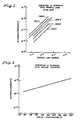
- the response increases with applied potential at a given electrode separation, as illustrated in Figure 2.
- a good general working condition is a 5 mm electrode gap and fifteen hundred volts applied potential.
- an increase of applied potential to two thousand volts provides an order of magnitude increase in response, as shown by the graph of Figure 3.
- the area of emitter foil which is exposed is exposed.
- the electron flux is proportional to the surface area of the emitter exposed to the ultra-violet light and also to the intensity of the radiation.
- the anode 32 should present a smooth, polished, rounded surface. This avoids arcing at high voltages.
- Various modifications are also possible. These include, for example, a stainless steel construction utilising a minimum of plastics in order to electrically isolate the anode.
- the ultra-violet radiation may be introduced via a quartz light pipe and noise reduction may be achieved by introduction of a third electrode to collect the ions produced, as in Lovelock's triode detector.
- FIG. 4 A further example is illustrated in Figures 4 and 5.
- the use of photoemission as an electron source is employed in an electron capture detector.
- an ion chamber which contains a cloud of free electrons is maintained at a potential just sufficient for the collection of all the free electrons produced.
- a gas or vapour capable of capturing free electrons, a corresponding decrease in current flow is readily observable.
- This is a very sensitive detector for certain specific components, in particular, oxygen and halogenated compounds. Nitrogen is the most commonly used carrier gas.
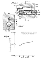
- the electron capture detector illustrated in Figures 4 and 5 comprises a metallic body 52 which may be, for example, of stainless steel or aluminium. It has a horizontal cylindrical bore 54 therethrough and a parallel, cylindrical recess 56 extending substantially therethrough. The bore 54 and the recess 56 are joined by a vertical slot 58. The left hand end of the recess 56, as viewed in Figure 4, is provided with a flare 60 so as to receive and conform to the shape of an ultra-violet lamp 62.
- the inner surfaces of recess 56, slot 58 and bore 54 are highly polished to enhance the reflection of ultra-violet radiation.
- a quartz tube 64 is mounted within the bore 54. In one embodiment, this tube was 45 mm long and had an internal diameter of 14 mm. The ends of the tube are terminated by PTFE plugs 66, 68. The plugs 66, 68 have identical co-axial openings therethrough for receiving respective cathode 70 and anode 72, each of which is formed from a stainless steel tube of 1/16 inch (1.6 mm) outside diameter and 1/32 inch (0.793 mm) inside diameter. In addition, the plug 66 is provided with scavenging holes 74. Mounted within and against the lower inner circumference of the quartz tube 64 is a piece of photoemissive foil 76 electrically connected to the cathode 70 by means of a lead 78. In an actual embodiment, the foil 76 was 15 x 25 mm in size.
- the ultra-violet lamp 62 has a Hamamatsu ultra-violet lamp and, as will be apparent from the drawings, its radiation was caused to pass directly through the slot 58 and the quartz tube 64 onto the surface of the photoemissive foil 76.
- the standing current thereby achieved at various applied voltages is shown in the graph of Figure 6.
- a detector constructed in accordance with the foregoing description was set up with a nitrogen flow of 50 ml per minute passing in through the cathode 70.
- This detector responded well to samples of dichloroethane, chloroform, and trichloroethylene. However, hexane and heptane resulted in substantially no response. This clearly illustrated that the detector operated in the electron capture mode, as only halogenated compounds gave suitable responses.
- the ultra-violet lamp may be totally contained within the detector body so that ultra-violet energy may radiate over a cylinder the length of the emitter.
- ultra-violet energy may be passed into a cell through a light pipe having a hemispherical end to ensure even distribution of radiation.
- Another modification employs the ultra-violet lamp as an anode by covering it with a fine metal mesh.
- scavenging gas may be admitted into the detector cell, ideally as an annular flow close to the walls of the detector cell, while the sample enters the cell axially. This helps protect the emitter from contamination.
Landscapes
- Chemical & Material Sciences (AREA)
- Health & Medical Sciences (AREA)
- Immunology (AREA)
- Pathology (AREA)
- Analytical Chemistry (AREA)
- Biochemistry (AREA)
- General Health & Medical Sciences (AREA)
- General Physics & Mathematics (AREA)
- Physics & Mathematics (AREA)
- Life Sciences & Earth Sciences (AREA)
- Toxicology (AREA)
- Chemical Kinetics & Catalysis (AREA)
- Electrochemistry (AREA)
- Other Investigation Or Analysis Of Materials By Electrical Means (AREA)
- Photometry And Measurement Of Optical Pulse Characteristics (AREA)
- Investigating Or Analysing Materials By Optical Means (AREA)
Abstract
Description
- This invention pertains to gas chromatography detectors of the ionization type.
- Ionization detectors for gas chromatography are well known in the art. A comprehensive survey of such detectors as of 1961 may be found in an article entitled "Ionization Methods for the Analysis of Gases and Vapors" by J. E. Lovelock, Analytical Chemistry, Volume 33, No.2, February 1961, pages 162 - 178. The detectors reviewed in that article include, inter alia, the cross section ionization detector, the argon detector, and the electron capture detector. These detectors are characterised by the fact that each includes a source of ionizing radiation, i.e. a radioactive material.
- The use of radioactive substances in chromatographic detectors necessarily introduces certain health risks into the laboratory and complicates such tasks as cleaning detectors after use. Because of these health risks, they are also subject to certain governmental controls which complicate their application and use.
- Ionization detectors have been developed which avoid the need for radioactive elements. However, in many cases, these are not suitable for use as argon and electron capture detectors for various reasons, including the fact that they may require gases other than the carrier or sample. Examples are the photoionization detector referred to in the above-mentioned Lovelock article and the flame ionization detector.
- More recently, an electron capture detector has been developed which utilised a thermionic emission electron source, and is described in U.S. patent no: 4,304,997. However, there are certain problems inherent in a thermionic detector. One such problem is that the emitting filament may be "poisoned" by components of many samples, i.e. components may be adsorbed on the surface and thereby reduce its thermal emission.
- The present invention thus relates to a detector for use in gas chromatography of the type which includes a detection chamber, an electrical potential established across the chamber, and means for supplying free electrons to the chamber. According to the present invention, the necessary electrons are supplied by irradiating a photoemissive element with ultra-violet radiation, thus avoiding the use of ionizing radiation, additional gases and heated filaments. In other words, a detector for use in gas chromatography including a detection chamber, means for establishing an electrical potential across the chamber, and means for supplying free electrons to the chamber is characterised in that the electron supplying means comprises a solid photoemissive element adjacent the chamber and means for irradiating the photoemissive element with ultra-violet radiation to release electrons therefrom.
- Examples of detector in accordance with the invention will now be described with reference to the accompanying drawings, in which:-
- Figure 1 is an illustration in partial cross-section of an argon detector;
- Figure 2 is a graph illustrating the response of the detector of Figure 1 with sample loads;
- Figure 3 is a graph illustrating the variation in the response of the detector of Figure 1 with applied potential;
- Figure 4 is a cross-section of an electron capture detector;
- Figure 5 is a cross-section taken substantially along the line 5 - 5 of Figure 4; and
- Figure 6 is a graph showing the variation in standing current with applied voltage of the detector of Figures 4 and 5.
- The detector shown in Figure 1 is of the type wherein the electrons raise argon to its metastable state. The
body 10 of the detector is a block of a substantially inert, non-metallic material, in this instance, polytetrafluoroethylene (PTFE). The block is drilled to provide a substantiallyhorizontal passage 12 extending from arecess 14 in the left side ofbody 10 as viewed in Figure 1. Thepassage 12 is co-axial with asmaller passage 16 which continues out of the right hand side of thebody 10. Thepassage 12 is intersected by a vertical passage 18 which communicates with a well 20 extending out of the bottom ofbody 10 and a larger tappedopening 22 which extends out the top ofbody 10. - The end of a
chromatographic column 24 is connected into thepassage 12 by means of a conventional stainless steel, liquid chromatograph column end fitting 26 carrying a two micronfrit disc 28. The fitting is push-fitted into therecess 14 and is in electrical connection with a tubular,copper foil electrode 30 lining thepassage 12. Theelectrode 30, fitting 26 andcolumn 24 comprise the cathode of the detector. The anode comprises astainless steel tube 32 inserted into thepassage 16. In one embodiment thetube 32 had an outer diameter of 1/16 inch (1.6 mm) and an inner diameter of 0.020 inch (0.51 mm). - Screwed into the tapped
opening 22 is a threadedplug 34 which is hollow and carries at its end aholder 36 to which is secured, as by cementing, a small piece of photoemissive foil 38. This foil may be any material which is activated by ultra-violet radiation. In one embodiment, approximately three square millimetres of an antimony/caesium (Sb/Cs) alloy foil emitter from an EMI 9781R photoemitter was employed. Other stable photoemitters could also be employed including, for example, the multi-alkali (Na-K-Sb-Cs) photocathode from a Hamamatsu R955 photo-multiplier tube. This material has a high radiation sensitivity between 930 nm and 160 nm. The foil 38 was electrically connected to the cathode by means of asuitable connector 40 andconductor 42. The ultra-violet source for the detector was a Hamamatsu "pencil"ultra-violet lamp 44 inserted into thewell 20. - Ultra-violet radiation from the
lamp 44 bombards the photoemissive foil 38, resulting in a cloud of electrons in the detection chamber formed bypassage 12. When argon (or a similarly acting gas such as helium) is used as the carrier to elute samples from thechromatographic column 24, the argon atoms are raised to their metastable state by electron collisions and then ionize the sample molecules as explained by Lovelock. This causes a current flow across the applied potential betweenanode 32 andcathode 30 produced by thepower supply 46. This current flow is amplified byamplifier 48 and recorded byrecorder 50. - The position of the
anode 32 with respect to thecathode 30 determines the level of response at a given applied potential. The response increases with applied potential at a given electrode separation, as illustrated in Figure 2. A good general working condition is a 5 mm electrode gap and fifteen hundred volts applied potential. For more sensitive modes of operation, an increase of applied potential to two thousand volts provides an order of magnitude increase in response, as shown by the graph of Figure 3. - Another factor affecting operation of the detector is the area of emitter foil which is exposed. Obviously, the electron flux is proportional to the surface area of the emitter exposed to the ultra-violet light and also to the intensity of the radiation. Furthermore, it is important that the
anode 32 should present a smooth, polished, rounded surface. This avoids arcing at high voltages. Various modifications are also possible. These include, for example, a stainless steel construction utilising a minimum of plastics in order to electrically isolate the anode. Also, the ultra-violet radiation may be introduced via a quartz light pipe and noise reduction may be achieved by introduction of a third electrode to collect the ions produced, as in Lovelock's triode detector. - A further example is illustrated in Figures 4 and 5. In this example, the use of photoemission as an electron source is employed in an electron capture detector. As is well known, in an electron capture detector, an ion chamber which contains a cloud of free electrons is maintained at a potential just sufficient for the collection of all the free electrons produced. When there is introduced into such an ion chamber, a gas or vapour capable of capturing free electrons, a corresponding decrease in current flow is readily observable. This is a very sensitive detector for certain specific components, in particular, oxygen and halogenated compounds. Nitrogen is the most commonly used carrier gas.
- The electron capture detector illustrated in Figures 4 and 5 comprises a
metallic body 52 which may be, for example, of stainless steel or aluminium. It has a horizontalcylindrical bore 54 therethrough and a parallel,cylindrical recess 56 extending substantially therethrough. Thebore 54 and therecess 56 are joined by avertical slot 58. The left hand end of therecess 56, as viewed in Figure 4, is provided with aflare 60 so as to receive and conform to the shape of anultra-violet lamp 62. The inner surfaces ofrecess 56,slot 58 and bore 54 are highly polished to enhance the reflection of ultra-violet radiation. - A
quartz tube 64 is mounted within thebore 54. In one embodiment, this tube was 45 mm long and had an internal diameter of 14 mm. The ends of the tube are terminated by PTFE plugs 66, 68. Theplugs 66, 68 have identical co-axial openings therethrough for receiving respective cathode 70 andanode 72, each of which is formed from a stainless steel tube of 1/16 inch (1.6 mm) outside diameter and 1/32 inch (0.793 mm) inside diameter. In addition, the plug 66 is provided with scavenging holes 74. Mounted within and against the lower inner circumference of thequartz tube 64 is a piece ofphotoemissive foil 76 electrically connected to the cathode 70 by means of alead 78. In an actual embodiment, thefoil 76 was 15 x 25 mm in size. - The
ultra-violet lamp 62 has a Hamamatsu ultra-violet lamp and, as will be apparent from the drawings, its radiation was caused to pass directly through theslot 58 and thequartz tube 64 onto the surface of thephotoemissive foil 76. The standing current thereby achieved at various applied voltages is shown in the graph of Figure 6. - A detector constructed in accordance with the foregoing description was set up with a nitrogen flow of 50 ml per minute passing in through the cathode 70. This detector responded well to samples of dichloroethane, chloroform, and trichloroethylene. However, hexane and heptane resulted in substantially no response. This clearly illustrated that the detector operated in the electron capture mode, as only halogenated compounds gave suitable responses.
- A number of variations may be made in the design and construction of this modification of electron detector cell. For example, the ultra-violet lamp may be totally contained within the detector body so that ultra-violet energy may radiate over a cylinder the length of the emitter. Alternatively, ultra-violet energy may be passed into a cell through a light pipe having a hemispherical end to ensure even distribution of radiation. These techniques enable construction of a smaller cell which can be more readily scavenged. Another modification employs the ultra-violet lamp as an anode by covering it with a fine metal mesh. Furthermore, scavenging gas may be admitted into the detector cell, ideally as an annular flow close to the walls of the detector cell, while the sample enters the cell axially. This helps protect the emitter from contamination.
Claims (9)
Applications Claiming Priority (2)
| Application Number | Priority Date | Filing Date | Title |
|---|---|---|---|
| GB848431663A GB8431663D0 (en) | 1984-12-14 | 1984-12-14 | Ionization detector |
| GB8431663 | 1984-12-14 |
Publications (2)
| Publication Number | Publication Date |
|---|---|
| EP0184892A1 true EP0184892A1 (en) | 1986-06-18 |
| EP0184892B1 EP0184892B1 (en) | 1992-08-19 |
Family
ID=10571221
Family Applications (1)
| Application Number | Title | Priority Date | Filing Date |
|---|---|---|---|
| EP85305196A Expired EP0184892B1 (en) | 1984-12-14 | 1985-07-22 | Ionization detector for gas chromatography and method therefor |
Country Status (6)
| Country | Link |
|---|---|
| US (1) | US4740695A (en) |
| EP (1) | EP0184892B1 (en) |
| JP (1) | JPH0625753B2 (en) |
| CA (1) | CA1233878A (en) |
| DE (1) | DE3586529T2 (en) |
| GB (1) | GB8431663D0 (en) |
Cited By (4)
| Publication number | Priority date | Publication date | Assignee | Title |
|---|---|---|---|---|
| EP0321745A2 (en) * | 1987-12-04 | 1989-06-28 | O.I. Corporation | Photoionization detector for gas chromatography |
| GB2173635B (en) * | 1985-03-15 | 1989-11-01 | Secr Defence | An electron capture detector |
| GB2255440A (en) * | 1991-03-12 | 1992-11-04 | Mks Instr Inc | Ionisation gauge. |
| GB2315154A (en) * | 1996-07-09 | 1998-01-21 | Bruker Saxonia Analytik Gmbh | Electron capture detector |
Families Citing this family (9)
| Publication number | Priority date | Publication date | Assignee | Title |
|---|---|---|---|---|
| GB2183897B (en) * | 1985-10-30 | 1990-07-11 | Perkin Elmer Corp | Ionization detectors for gas chromatography |
| US4988870A (en) * | 1989-10-10 | 1991-01-29 | Und-Sem Foundation | Open-split interface for mass spectrometers |
| US5760291A (en) * | 1996-09-03 | 1998-06-02 | Hewlett-Packard Co. | Method and apparatus for mixing column effluent and make-up gas in an electron capture detector |
| US5739699A (en) * | 1996-09-03 | 1998-04-14 | Hewlett-Packard Company | Method and apparatus for ion discrimination in an electron capture detector |
| US5804828A (en) * | 1996-09-30 | 1998-09-08 | Hewlett-Packard Company | Method and apparatus for optimizing the sensitivity and linearity of an electron capture detector |
| US5892364A (en) * | 1997-09-11 | 1999-04-06 | Monagle; Matthew | Trace constituent detection in inert gases |
| US9310308B2 (en) | 2012-12-07 | 2016-04-12 | Ldetek Inc. | Micro-plasma emission detector unit and method |
| US10126278B2 (en) | 2016-03-04 | 2018-11-13 | Ldetek Inc. | Thermal stress resistant micro-plasma emission detector unit |
| WO2019144228A1 (en) | 2018-01-23 | 2019-08-01 | Ldetek Inc. | Valve assembly for a gas chromatograph |
Citations (3)
| Publication number | Priority date | Publication date | Assignee | Title |
|---|---|---|---|---|
| US3238367A (en) * | 1963-02-20 | 1966-03-01 | Beckman Instruments Inc | Device for the analysis of a fluent material by bombarding the same with photoelectrons |
| GB1088922A (en) * | 1964-05-29 | 1967-10-25 | Philips Electronic Associated | Improvements in or relating to gas chromatography detectors |
| DD119874A1 (en) * | 1975-06-06 | 1976-05-12 |
Family Cites Families (8)
| Publication number | Priority date | Publication date | Assignee | Title |
|---|---|---|---|---|
| US2950381A (en) * | 1960-04-15 | 1960-08-23 | Ronald F Brennen | Welding electrode feeding apparatus |
| JPS4219671Y1 (en) * | 1964-02-15 | 1967-11-14 | ||
| US3824684A (en) * | 1973-08-27 | 1974-07-23 | Black & Decker Mfg Co | Method of assembling an electric motor device and heat sink |
| JPS5522741B2 (en) * | 1975-01-16 | 1980-06-18 | ||
| GB1571799A (en) * | 1975-12-15 | 1980-07-16 | Secr Defence | Detection of polar vapours |
| US4377749A (en) * | 1981-02-25 | 1983-03-22 | Young Robert A | Photoionizer |
| US4413185A (en) * | 1981-04-29 | 1983-11-01 | Her Majesty The Queen In Right Of Canada, As Represented By The Minister Of National Defence | Selective photoionization gas chromatograph detector |
| US4476392A (en) * | 1981-12-28 | 1984-10-09 | Young Robert A | Photoelectron source for use in a gas chromatograph detector and mass spectrometer ion source |
-
1984
- 1984-12-14 GB GB848431663A patent/GB8431663D0/en active Pending
-
1985
- 1985-07-22 EP EP85305196A patent/EP0184892B1/en not_active Expired
- 1985-07-22 DE DE8585305196T patent/DE3586529T2/en not_active Expired - Fee Related
- 1985-10-15 US US06/787,563 patent/US4740695A/en not_active Expired - Lifetime
- 1985-10-18 CA CA000493359A patent/CA1233878A/en not_active Expired
- 1985-12-13 JP JP60279392A patent/JPH0625753B2/en not_active Expired - Lifetime
Patent Citations (3)
| Publication number | Priority date | Publication date | Assignee | Title |
|---|---|---|---|---|
| US3238367A (en) * | 1963-02-20 | 1966-03-01 | Beckman Instruments Inc | Device for the analysis of a fluent material by bombarding the same with photoelectrons |
| GB1088922A (en) * | 1964-05-29 | 1967-10-25 | Philips Electronic Associated | Improvements in or relating to gas chromatography detectors |
| DD119874A1 (en) * | 1975-06-06 | 1976-05-12 |
Cited By (9)
| Publication number | Priority date | Publication date | Assignee | Title |
|---|---|---|---|---|
| GB2173635B (en) * | 1985-03-15 | 1989-11-01 | Secr Defence | An electron capture detector |
| EP0321745A2 (en) * | 1987-12-04 | 1989-06-28 | O.I. Corporation | Photoionization detector for gas chromatography |
| EP0321745A3 (en) * | 1987-12-04 | 1991-01-16 | O.I. Corporation | Photoionization detector for gas chromatography |
| GB2255440A (en) * | 1991-03-12 | 1992-11-04 | Mks Instr Inc | Ionisation gauge. |
| US5198772A (en) * | 1991-03-12 | 1993-03-30 | Mks Instruments, Inc. | Removable discharge initiating means for cold cathode discharge ionization gauge |
| GB2255440B (en) * | 1991-03-12 | 1995-01-25 | Mks Instr Inc | Improved discharge initiating means for cold cathode discharge ionization gauge |
| GB2315154A (en) * | 1996-07-09 | 1998-01-21 | Bruker Saxonia Analytik Gmbh | Electron capture detector |
| US6023169A (en) * | 1996-07-09 | 2000-02-08 | Bruker-Saxonia Analytik Gmbh | Electron capture detector |
| GB2315154B (en) * | 1996-07-09 | 2001-01-24 | Bruker Saxonia Analytik Gmbh | Electron capture detector |
Also Published As
| Publication number | Publication date |
|---|---|
| GB8431663D0 (en) | 1985-01-30 |
| US4740695A (en) | 1988-04-26 |
| CA1233878A (en) | 1988-03-08 |
| JPS61144564A (en) | 1986-07-02 |
| JPH0625753B2 (en) | 1994-04-06 |
| EP0184892B1 (en) | 1992-08-19 |
| DE3586529T2 (en) | 1993-01-21 |
| DE3586529D1 (en) | 1992-09-24 |
Similar Documents
| Publication | Publication Date | Title |
|---|---|---|
| US6333632B1 (en) | Alternating current discharge ionization detector | |
| EP0184892A1 (en) | Ionization detector for gas chromatography and method therefor | |
| US5889404A (en) | Discharge ionization detector having efficient transfer of metastables for ionization of sample molecules | |
| US4789783A (en) | Discharge ionization detector | |
| US6023169A (en) | Electron capture detector | |
| US4812040A (en) | Hollow cathode plasma plume | |
| US4304997A (en) | Electron capture detector with thermionic emission electron source | |
| US3176135A (en) | Apparatus for detecting and analysing low gaseous concentrations | |
| US3478205A (en) | Ionization detector electrode assembly and method of analyzing gas and vapor substances | |
| EP1279955B2 (en) | Helium ionization detector | |
| JP3907796B2 (en) | Electron capture type detection device and electron capture type detection method | |
| US4264817A (en) | Coaxial electron capture detector with thermionic emission electron source | |
| US5920072A (en) | Ionization detector | |
| US4137453A (en) | Methods and apparatus for improving electron capture detectors by collection of ions | |
| EP0292974A2 (en) | Atmospheric sampling glow discharge ionization source | |
| US4873862A (en) | Ionization detectors for gas chromatography | |
| EP0831325B1 (en) | Method and apparatus for ion discrimination in an electron capture detector | |
| US4713548A (en) | Electron attachment apparatus and method | |
| US4837441A (en) | Ionization detectors for gas chromatography | |
| US3110809A (en) | Apparatus for detecting and analyzing low gaseous concentrations | |
| US5126676A (en) | Gas amplified ionization detector for gas chromatography | |
| Simmonds | Electron-capture detector with a photoemissive electron source | |
| US6107805A (en) | Extended detection zone in an ionization detector | |
| US4051376A (en) | Ionization detectors | |
| US3400264A (en) | Dual column gas chromatography apparatus |
Legal Events
| Date | Code | Title | Description |
|---|---|---|---|
| PUAI | Public reference made under article 153(3) epc to a published international application that has entered the european phase |
Free format text: ORIGINAL CODE: 0009012 |
|
| AK | Designated contracting states |
Kind code of ref document: A1 Designated state(s): CH DE FR GB LI NL |
|
| 17P | Request for examination filed |
Effective date: 19861029 |
|
| 17Q | First examination report despatched |
Effective date: 19880331 |
|
| GRAA | (expected) grant |
Free format text: ORIGINAL CODE: 0009210 |
|
| AK | Designated contracting states |
Kind code of ref document: B1 Designated state(s): CH DE FR GB LI NL |
|
| REF | Corresponds to: |
Ref document number: 3586529 Country of ref document: DE Date of ref document: 19920924 |
|
| ET | Fr: translation filed | ||
| PLBE | No opposition filed within time limit |
Free format text: ORIGINAL CODE: 0009261 |
|
| STAA | Information on the status of an ep patent application or granted ep patent |
Free format text: STATUS: NO OPPOSITION FILED WITHIN TIME LIMIT |
|
| 26N | No opposition filed | ||
| REG | Reference to a national code |
Ref country code: GB Ref legal event code: 732E |
|
| PGFP | Annual fee paid to national office [announced via postgrant information from national office to epo] |
Ref country code: NL Payment date: 20000703 Year of fee payment: 16 Ref country code: GB Payment date: 20000703 Year of fee payment: 16 Ref country code: DE Payment date: 20000703 Year of fee payment: 16 |
|
| PGFP | Annual fee paid to national office [announced via postgrant information from national office to epo] |
Ref country code: CH Payment date: 20000705 Year of fee payment: 16 |
|
| PGFP | Annual fee paid to national office [announced via postgrant information from national office to epo] |
Ref country code: FR Payment date: 20000706 Year of fee payment: 16 |
|
| PG25 | Lapsed in a contracting state [announced via postgrant information from national office to epo] |
Ref country code: GB Free format text: LAPSE BECAUSE OF NON-PAYMENT OF DUE FEES Effective date: 20010722 |
|
| PG25 | Lapsed in a contracting state [announced via postgrant information from national office to epo] |
Ref country code: LI Free format text: LAPSE BECAUSE OF NON-PAYMENT OF DUE FEES Effective date: 20010731 Ref country code: CH Free format text: LAPSE BECAUSE OF NON-PAYMENT OF DUE FEES Effective date: 20010731 |
|
| PG25 | Lapsed in a contracting state [announced via postgrant information from national office to epo] |
Ref country code: NL Free format text: LAPSE BECAUSE OF NON-PAYMENT OF DUE FEES Effective date: 20020201 |
|
| GBPC | Gb: european patent ceased through non-payment of renewal fee |
Effective date: 20010722 |
|
| REG | Reference to a national code |
Ref country code: CH Ref legal event code: PL |
|
| PG25 | Lapsed in a contracting state [announced via postgrant information from national office to epo] |
Ref country code: FR Free format text: LAPSE BECAUSE OF NON-PAYMENT OF DUE FEES Effective date: 20020329 |
|
| NLV4 | Nl: lapsed or anulled due to non-payment of the annual fee |
Effective date: 20020201 |
|
| PG25 | Lapsed in a contracting state [announced via postgrant information from national office to epo] |
Ref country code: DE Free format text: LAPSE BECAUSE OF NON-PAYMENT OF DUE FEES Effective date: 20020501 |
|
| REG | Reference to a national code |
Ref country code: FR Ref legal event code: ST |