EP0321737B1 - Miniaturisierte Referenzelektroden - Google Patents
Miniaturisierte Referenzelektroden Download PDFInfo
- Publication number
- EP0321737B1 EP0321737B1 EP88119781A EP88119781A EP0321737B1 EP 0321737 B1 EP0321737 B1 EP 0321737B1 EP 88119781 A EP88119781 A EP 88119781A EP 88119781 A EP88119781 A EP 88119781A EP 0321737 B1 EP0321737 B1 EP 0321737B1
- Authority
- EP
- European Patent Office
- Prior art keywords
- reference electrode
- opening
- silver
- electrode according
- ratio
- Prior art date
- Legal status (The legal status is an assumption and is not a legal conclusion. Google has not performed a legal analysis and makes no representation as to the accuracy of the status listed.)
- Expired - Lifetime
Links
- 239000003792 electrolyte Substances 0.000 claims abstract description 13
- GTKRFUAGOKINCA-UHFFFAOYSA-M chlorosilver;silver Chemical compound [Ag].[Ag]Cl GTKRFUAGOKINCA-UHFFFAOYSA-M 0.000 claims abstract description 11
- 229910021607 Silver chloride Inorganic materials 0.000 claims description 15
- BQCADISMDOOEFD-UHFFFAOYSA-N Silver Chemical compound [Ag] BQCADISMDOOEFD-UHFFFAOYSA-N 0.000 claims description 14
- 239000004332 silver Substances 0.000 claims description 14
- HKZLPVFGJNLROG-UHFFFAOYSA-M silver monochloride Chemical compound [Cl-].[Ag+] HKZLPVFGJNLROG-UHFFFAOYSA-M 0.000 claims description 13
- 229910052709 silver Inorganic materials 0.000 claims description 12
- WCUXLLCKKVVCTQ-UHFFFAOYSA-M Potassium chloride Chemical group [Cl-].[K+] WCUXLLCKKVVCTQ-UHFFFAOYSA-M 0.000 claims description 10
- 238000009792 diffusion process Methods 0.000 claims description 9
- 239000011159 matrix material Substances 0.000 claims description 8
- 239000000758 substrate Substances 0.000 claims description 8
- 229920002401 polyacrylamide Polymers 0.000 claims description 7
- 229910001508 alkali metal halide Inorganic materials 0.000 claims description 5
- 150000008045 alkali metal halides Chemical class 0.000 claims description 5
- 239000001103 potassium chloride Substances 0.000 claims description 5
- 235000011164 potassium chloride Nutrition 0.000 claims description 5
- FAPWRFPIFSIZLT-UHFFFAOYSA-M Sodium chloride Chemical compound [Na+].[Cl-] FAPWRFPIFSIZLT-UHFFFAOYSA-M 0.000 claims description 4
- 239000011780 sodium chloride Substances 0.000 claims description 2
- 239000012530 fluid Substances 0.000 claims 1
- 230000000694 effects Effects 0.000 abstract description 3
- 239000000499 gel Substances 0.000 description 13
- 229940075397 calomel Drugs 0.000 description 12
- ZOMNIUBKTOKEHS-UHFFFAOYSA-L dimercury dichloride Chemical compound Cl[Hg][Hg]Cl ZOMNIUBKTOKEHS-UHFFFAOYSA-L 0.000 description 12
- 150000002500 ions Chemical class 0.000 description 5
- 238000005259 measurement Methods 0.000 description 5
- 238000012360 testing method Methods 0.000 description 5
- 239000000178 monomer Substances 0.000 description 4
- 238000002474 experimental method Methods 0.000 description 2
- 238000000034 method Methods 0.000 description 2
- 229920003023 plastic Polymers 0.000 description 2
- 239000004033 plastic Substances 0.000 description 2
- 230000000379 polymerizing effect Effects 0.000 description 2
- VHUUQVKOLVNVRT-UHFFFAOYSA-N Ammonium hydroxide Chemical compound [NH4+].[OH-] VHUUQVKOLVNVRT-UHFFFAOYSA-N 0.000 description 1
- 239000004593 Epoxy Substances 0.000 description 1
- 239000004676 acrylonitrile butadiene styrene Substances 0.000 description 1
- 239000000908 ammonium hydroxide Substances 0.000 description 1
- 238000007772 electroless plating Methods 0.000 description 1
- 239000011521 glass Substances 0.000 description 1
- 230000000670 limiting effect Effects 0.000 description 1
- 239000000463 material Substances 0.000 description 1
- 229910052724 xenon Inorganic materials 0.000 description 1
- FHNFHKCVQCLJFQ-UHFFFAOYSA-N xenon atom Chemical compound [Xe] FHNFHKCVQCLJFQ-UHFFFAOYSA-N 0.000 description 1
Images


Classifications
-
- G—PHYSICS
- G01—MEASURING; TESTING
- G01N—INVESTIGATING OR ANALYSING MATERIALS BY DETERMINING THEIR CHEMICAL OR PHYSICAL PROPERTIES
- G01N27/00—Investigating or analysing materials by the use of electric, electrochemical, or magnetic means
- G01N27/26—Investigating or analysing materials by the use of electric, electrochemical, or magnetic means by investigating electrochemical variables; by using electrolysis or electrophoresis
- G01N27/28—Electrolytic cell components
- G01N27/30—Electrodes, e.g. test electrodes; Half-cells
- G01N27/301—Reference electrodes
Definitions
- This invention relates to reference electrodes for use in potentiometric measurements.
- Reference electrodes provide a reference potential in electrochemical cells used for the measurement of ion activity.
- a reference electrode is typically used with an ion selective electrode to obtain a potentiometric signal relating to ion activity in a solution in which the two electrodes are introduced.
- a reference electrode is supposed to provide a stable and unchanging reference potential.
- the present invention is a miniaturized reference electrode which can be constructed inexpensively, and can be disposed of even after a single use. Preferably, however, the same electrode can be used a number of times, over 200 times, in fact.
- the reference electrode of this invention also reaches equilibrium rapidly typically less than twenty seconds, and is stable over a broad temperature and pressure range.
- the reference electrode of this invention includes a silver-silver chloride chip and a housing having an internal cavity filled with electrolyte.
- the cavity has a first opening across which the chip is disposed, and a second opening spaced from the first opening.
- the ratio of the area of the first opening to the area of the second opening ranges from about 14.0 to about 728.0.
- the ratio of the distance between the first and second openings to the area of the first opening is about 2.0 cm ⁇ 1 to about 66.0 cm ⁇ 1.
- extremely small reference electrodes can be constructed wherein the area of the second opening ranges from about 8.00 x 10 ⁇ 5 cm2 to about 3.3 x 10 ⁇ 4 cm2.
- Such reference electrodes are extremely small and can be designed by varying the amount of silver-silver chloride matrix in the electrode to be disposable after a single use or after multiple uses.
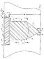
- the reference electrode 8 of the present invention includes a housing 10 ( Figure 1).
- Housing 10 includes a first opening 12 across which a silver-silver chloride chip 14 is disposed.
- Housing 10 further includes a second opening 16 which will be exposed to the testing medium of interest. Between openings 12 and 16, housing 10 has an internal cavity 18 which is filled with electrolyte 20.
- Reference electrode 8 of this invention is capable of reaching stability within a relatively short period of time (e.g., typically less than 20 seconds) due to its unique proportions and size.
- the ratio of the area of first opening 12 to the area of second opening 16 ranges from about 14.0 to about 728.0. Preferably, this ratio is about 143.3.
- openings 12 and 16 are circular; however, their circular shapes are not critical.
- the area of first opening 12 is about 1.82 x 10 ⁇ 2 cm2, and the area of the second opening is about 1.27 x 10 ⁇ 4 cm2.
- the ratio of distance "d” i.e., the distance between openings 12 and 16
- the area of first opening 12 ranges from about 2.0 cm ⁇ 1 to about 66.0 cm ⁇ 1.
- this second ratio is about 13.3 cm ⁇ 1.
- Cavity 18 can be divided into two zones: reservoir 22 and diffusion chamber 24.
- Reservoir 22 includes a cylindrical portion 26 which has the diameter of opening 12, and a tapering conical portion 28 which tapers from the diameter of cylindrical portion 26 to the diameter of diffusion chamber 24.
- Diffusion chamber 24 is cylindrical, it has the diameter of opening 16. Diffusion chamber 24 has a length ranging from about 1.02 x 10 ⁇ 2 cm to about 1.78 x 10 ⁇ 2 cm, preferably 1.27 x 10 ⁇ 2 cm. The ratio of the volume of the diffusion chamber to the volume of the rest of the internal cavity (reservoir 22) is about 5.90 x 10 ⁇ 5 to about 1.30 x 10 ⁇ 2, preferably 5.18 x 10 ⁇ 4.
- Silver/silver chloride chip 14 preferably comprises a silver-silver chloride matrix layer 30 which is applied to all surfaces of a substrate 32.
- Substrate 32 can be any inert material such as a plastic or glass.
- substrate 32 is made of a plastic such as acrylonitrile-butadiene-styrene (ABS).
- ABS acrylonitrile-butadiene-styrene
- the silver-silver chloride matrix layer 30 preferably includes a layer of silver which is deposited directly on substrate 32, and a layer of silver chloride which overlays the silver layer and is exposed directly to electrolyte 20. The silver and the silver chloride layers are applied to chip 32 by conventional electroless plating techniques.
- the silver layer is thicker than the silver chloride layer.
- the ratio of the thickness of the silver layer to the thickness of the silver chloride layer is 4 to 1.
- the exact thicknesses of the two layers depends in large part upon how long the reference electrode is designed to last. The thicknesses also depend on the two layers filling any irregularities in the surface of the substrate. If depressions or peaks in the substrate surface are not filled or covered, a non-homogeneous layer is formed which can reduce the effective surface area of the silver-silver chloride matrix layer.
- the silver layer can be about 1.27 x 10 ⁇ 4 cm thick, and the silver chloride layer can be 3.18 x 10 ⁇ 5 cm thick.
- a reference electrode of this invention has been constructed which can be used for over 200 separate measurements where the thickness of the silver layer is 2.54 x 10 ⁇ 4 cm and the thickness of the silver chloride layer is 6.35 x 10 ⁇ 5 cm.
- Silver/silver chloride chip 14 is positioned in a recess 34 adjacent opening 12 so that the silver-silver chloride matrix 30 of chip 14 is positioned across opening 12 in direct physical contact with electrolyte 20. Electrical contact to matrix 30 is established from the back side 31 of chip 14 by removing from the back side only the silver chloride layer, leaving the silver layer. The silver chloride layer is removed by exposing it to concentrated ammonium hydroxide. Once the silver chloride layer is removed, an electrical circuit is completed by the attachment of an electrical lead with conductive epoxy to the exposed silver layer of the back side 31 of chip 14.
- Electrolyte 20 fills internal cavity 18 completely-including reservoir 22 and diffusion chamber 24.
- Electrolyte 20 advantageously is a polyacrylamide gel which is impregnated with an alkali metal halide.
- Polyacrylamide gels can be polymerized externally, according to conventional procedures, and then packed into internal cavity 18 manually. It has been found that when the gel is packed manually into cavity 18, pockets of air can be introduced into the gel.
- the amount of polymerized gel can differ between reference electrodes packed manually. The differences in gel amounts lead to differences in impedance between electrodes. Accordingly, polymerizing the gel in place in cavity 18 is preferred.
- the polyacrylamide gel of electrolyte 20 can be polymerized in place by addition of the polyacrylamide in its monomer form into cavity 18 and exposing the monomer to an appropriate lamp source (e.g. a lamp source such as a Black-Ray lamp or a xenon flash tube).
- an appropriate lamp source e.g. a lamp source such as a Black-Ray lamp or a xenon flash tube.
- the advantage of polymerizing the polyacrylamide gel in place is that a precise amount of the relatively non-viscous monomer can be introduced into cavity 18 so that the cavity can be filled without any air pockets. When the monomer is then polymerized to form the gel, the gel conforms to the precise internal dimensions of cavity 18 and will completely fill it without air pockets.
- the alkali metal halide in the gel should be selected from potassium chloride or sodium chloride. The concentration of the alkali metal halide in the gel ranges from about .10 M to about .30 M, preferably .15 M.
- a reference electrode constructed according to the teachings of this invention will have an impedance from about 12 to about 25 kiloohms. This impedance has been found to be lower than the impedance of ion selective electrodes such as the one disclosed in U.S. Patent Application 056,605 filed June 1, 1987 entitled “Apparatus for Measuring Electrolytes", which application is incorporated herein by reference. Such a reference electrode can be used in tandem with the ion selective electrode in the aforesaid patent application.
- the reference electrode of the present invention can stabilize quickly when exposed to a solution containing electrolytes to be measured.
- the rapidity with which the reference electrode of this invention can reach a stable plateau is illustrated by Figure 5.
- the data plotted on Figure 5 is attained by constructing a test apparatus which includes a thermostated beaker filled with .15 M potassium chloride into which three electrodes are placed: the reference electrode of this invention, and two commercially available calomel electrodes (Corning calomel electrode model no. 80062). The two calomel electrodes are preconditioned in the potassium chloride solution for about 20 minutes. The electrolyte inside the reference electrode in this experiment was also .15 M potassium chloride.
- the potential between the two calomel electrodes is measured over time, for about three minutes. This acts as a control potential in determining any potential fluctuations as a result of changes within the control solution itself, or any changes due to temperature, pressure and the like. If the potential measured between the two calomel electrodes is relatively constant over the three minute test period, it establishes that the calomel electrodes are working properly.
- the stability of the reference electrode can be measured.
- the stability of the reference electrode is measured against one of the two calomel electrodes.
- the reference electrode is not introduced into the testing solution until after the proper functioning of the calomel electrodes is established.
- the potential between the reference electrode and one of the calomel electrodes is monitored continuously.
- These reference measurements are depicted in Figure 5 for the first three minutes after the reference electrode is introduced to the solution. While the reference electrode is in the solution, the potential between the two calomel electrodes is also monitored to insure that the calomel electrodes are functioning properly while the reference electrode is in solution.
- the data in Figure 5 illustrates that the reference electrode of this invention reaches stability in less than 20 seconds, and maintains that stability for over three minutes. In Applicant's experience, that stability will essentially be maintained for its useful life.
- the reference electrode used in the experiment of Figure 5 had a first opening with an area of 1.82 x 10 ⁇ 2 cm2, and a second opening with an area of 1.27 x 10 ⁇ 4 cm ⁇ 2.
- the ratio "d" was 13.3 cm ⁇ 1.
- Reference electrode of the present invention has a long shelf life between the time it is constructed and the time it is tested.
- Reference electrodes have been constructed according to the teachings of the present invention which exhibit stability even after three years of storage.
- the reference electrode of the present invention provides an inexpensive electrode which can be constructed to be disposable after one or multiple uses. Furthermore, it can reach a stable condition in a relatively short period of time in contrast to many prior art reference electrodes.
- the embodiments in which an exclusive property of privileges claimed are defined by the claims which follow.
Landscapes
- Chemical & Material Sciences (AREA)
- Life Sciences & Earth Sciences (AREA)
- Health & Medical Sciences (AREA)
- General Physics & Mathematics (AREA)
- Pathology (AREA)
- Electrochemistry (AREA)
- Physics & Mathematics (AREA)
- Analytical Chemistry (AREA)
- Biochemistry (AREA)
- General Health & Medical Sciences (AREA)
- Molecular Biology (AREA)
- Immunology (AREA)
- Chemical Kinetics & Catalysis (AREA)
- Battery Electrode And Active Subsutance (AREA)
- Investigating Or Analyzing Materials By The Use Of Electric Means (AREA)
- Measurement Of Radiation (AREA)
- Electron Sources, Ion Sources (AREA)
- Investigating Or Analysing Biological Materials (AREA)
- Measurement Of The Respiration, Hearing Ability, Form, And Blood Characteristics Of Living Organisms (AREA)
- Hybrid Cells (AREA)
- Lasers (AREA)
- Measuring Oxygen Concentration In Cells (AREA)
Claims (16)
- Eine Bezugselektrode, bestehend aus:
einem Silber-Silberchlorid-Chip (14) und
einem Gehäuse (10) mit einem inneren Hohlraum (18), der mit Elektrolyt (20) gefüllt ist, wobei der Hohlraum (18) eine erste Öffnung (12) hat, wobei der Chip (14) derart angeordnet ist, daß er sich über der ersten Öffnung (12) erstreckt und diese im wesentlichen überdeckt, und eine zweite Öffnung (16), die zur ersten Öffnung (12) beabstandet ist,
wobei das Verhältnis der Fläche der ersten Öffnung (12) zur Fläche der zweiten Öffnung (16) 14,0 bis 728,0 beträgt, und
das Verhältnis des Abstandes zwischen der ersten und der zweiten Öffnung (12,16) zur Fläche der ersten Öffnung (12) 2,0 cm⁻¹ bis 66,0 cm⁻¹ beträgt. - Die Bezugselektrode nach Anspruch 1, dadurch gekennzeichnet, daß das Verhältnis der Flächen der ersten und der zweiten Öffnung (12,16) 143,3 beträgt.
- Die Bezugselektrode nach einem oder mehreren der vorhergehenden Ansprüche, dadurch gekennzeichnet, daß das Verhältnis dieses Abstandes zur Fläche der ersten Öffnung (12) 13,3 cm⁻¹ beträgt.
- Die Bezugselektrode nach einem oder mehreren der vorhergehenden Ansprüche, dadurch gekennzeichnet, daß die Fläche der zweiten Öffnung (16) 8,00 x 10⁻⁵ cm² bis 3,3 x 10⁻⁴ cm² beträgt.
- Die Bezugselektrode nach einem oder mehreren der vorhergehenden Ansprüche, dadurch gekennzeichnet, daß die Fläche der zweiten Öffnung (16) etwa 1,27 x 10⁻⁴ cm²
- Die Bezugselektrode nach einem oder mehreren der vorhergehenden Ansprüche, dadurch gekennzeichnet, daß die Fläche der ersten Öffnung (12) etwa 1,82 x 10⁻² cm² beträgt.
- Die Bezugselektrode nach einem oder mehreren der vorhergehenden Ansprüche, dadurch gekennzeichnet, daß der Chip (14) aus einem inerten Substrat (32) mit einer Silber-Silberchlorid-Matrix (30) besteht.
- Die Bezugselektrode nach Anspruch 7, dadurch gekennzeichnet, daß die Silber-Silberchlorid-Matrix (30) aus einer Silberchloridschicht auf einer Silberschicht besteht, wobei die Silberschicht auf das Substrat (32) aufgebracht worden ist.
- Die Bezugselektrode nach Anspruch 8, dadurch gekennzeichnet, daß das Verhältnis der Stärke der Silberschicht zu der Stärke der Silberchloridschicht 4:1 ist.
- Die Bezugselektrode nach einem oder mehreren der vorhergehenden Ansprüche, dadurch gekennzeichnet, daß das Elektrolyt (20) aus einem Polyacrylamidgel besteht, das mit einem Alkalimetallhalogenid getränkt ist.
- Die Bezugselektrode nach Anspruch 10, dadurch gekennzeichnet, daß das Alkalimetallhalogenid aus Kaliumchlorid oder Natriumchlorid gewählt wird.
- Die Bezugselektrode nach einem der Ansprüche 10-11, dadurch gekennzeichnet, daß das Polyacrylamid in dem Gehäuse (10) polymerisiert wird.
- Die Bezugselektrode nach einem oder mehreren der vorhergehenden Ansprüche, dadurch gekennzeichnet, daß die Impedanz der Elektrode 12 bis 25 Kiloohm beträgt.
- Die Bezugselektrode nach einem oder mehreren der vorhergehenden Ansprüche, dadurch gekennzeichnet, daß sie desweiteren eine Diffusionskammer (24) angrenzend an die zweite Öffnung (16) enthält, wobei die Diffusionskammer (16) mit dem inneren Hohlraum (18) kommuniziert.
- Die Bezugselektrode nach Anspruch 14, dadurch gekennzeichnet, daß das Verhältnis des Volumens der Diffusionskammer (24) zum Volumen des inneren Hohlraums (18) 5,90 x 10⁻⁵ bis 1,30 x 10⁻² beträgt.
- Die Bezugselektrode nach Anspruch 15, dadurch gekennzeichnet, daß das Verhältnis der Volumen etwa 5,18 x 10⁻⁴ ist.
Applications Claiming Priority (2)
| Application Number | Priority Date | Filing Date | Title |
|---|---|---|---|
| US07/136,886 US4836908A (en) | 1987-12-22 | 1987-12-22 | Miniaturized reference electrodes |
| US136886 | 1987-12-22 |
Publications (3)
| Publication Number | Publication Date |
|---|---|
| EP0321737A2 EP0321737A2 (de) | 1989-06-28 |
| EP0321737A3 EP0321737A3 (en) | 1990-08-01 |
| EP0321737B1 true EP0321737B1 (de) | 1994-08-03 |
Family
ID=22474836
Family Applications (1)
| Application Number | Title | Priority Date | Filing Date |
|---|---|---|---|
| EP88119781A Expired - Lifetime EP0321737B1 (de) | 1987-12-22 | 1988-11-28 | Miniaturisierte Referenzelektroden |
Country Status (9)
| Country | Link |
|---|---|
| US (1) | US4836908A (de) |
| EP (1) | EP0321737B1 (de) |
| JP (1) | JPH01207656A (de) |
| KR (1) | KR890010568A (de) |
| AT (1) | ATE109565T1 (de) |
| AU (1) | AU595734B2 (de) |
| CA (1) | CA1290016C (de) |
| DE (1) | DE3850947T2 (de) |
| ES (1) | ES2060639T3 (de) |
Families Citing this family (5)
| Publication number | Priority date | Publication date | Assignee | Title |
|---|---|---|---|---|
| DE4302322C2 (de) * | 1993-01-28 | 1998-09-10 | Inst Chemo Biosensorik | Langlebige miniaturisierbare Referenzelektrode |
| US6214210B1 (en) * | 1994-11-08 | 2001-04-10 | Rockwell Technologies, Llc | Electrochemical surface analysis using deoxygenated gel electrolyte |
| DE10243569A1 (de) * | 2002-09-19 | 2004-04-01 | Infineon Technologies Ag | Schaltkreis-Anordnung und Verfahren zum Herstellen einer Schaltkreis-Anordnung |
| WO2009055092A1 (en) * | 2007-10-24 | 2009-04-30 | Ge Analytical Instruments, Inc. | A compact inexpensive reference electrode design with very small residual junction potentials, very low electrolyte leakage, and very low silver leakage |
| DE102008055082A1 (de) * | 2008-12-22 | 2010-07-01 | Endress + Hauser Conducta Gesellschaft für Mess- und Regeltechnik mbH + Co. KG | Referenzelektrode |
Family Cites Families (7)
| Publication number | Priority date | Publication date | Assignee | Title |
|---|---|---|---|---|
| US3449232A (en) * | 1966-09-29 | 1969-06-10 | Us Navy | Stress corrosion cell |
| US3926764A (en) * | 1971-05-19 | 1975-12-16 | Radiometer As | Electrode for potentiometric measurements |
| US3960689A (en) * | 1974-01-28 | 1976-06-01 | Corning Glass Works | PH reference electrode |
| US4031606A (en) * | 1975-02-24 | 1977-06-28 | Honeywell Inc. | Method of making a combination ion responsive and reference electrode |
| GB1549044A (en) * | 1977-09-29 | 1979-08-01 | British Petroleum Co | Air gap electrode and method for using the electrode |
| US4592824A (en) * | 1985-09-13 | 1986-06-03 | Centre Suisse D'electronique Et De Microtechnique S.A. | Miniature liquid junction reference electrode and an integrated solid state electrochemical sensor including the same |
| US4980043A (en) * | 1986-12-11 | 1990-12-25 | Horiba, Ltd. | Reference electrode |
-
1987
- 1987-12-22 US US07/136,886 patent/US4836908A/en not_active Expired - Fee Related
-
1988
- 1988-11-28 ES ES88119781T patent/ES2060639T3/es not_active Expired - Lifetime
- 1988-11-28 DE DE3850947T patent/DE3850947T2/de not_active Expired - Fee Related
- 1988-11-28 EP EP88119781A patent/EP0321737B1/de not_active Expired - Lifetime
- 1988-11-28 AT AT88119781T patent/ATE109565T1/de not_active IP Right Cessation
- 1988-12-06 AU AU26608/88A patent/AU595734B2/en not_active Ceased
- 1988-12-20 KR KR1019880017009A patent/KR890010568A/ko not_active Application Discontinuation
- 1988-12-20 CA CA000586464A patent/CA1290016C/en not_active Expired - Fee Related
- 1988-12-21 JP JP63323202A patent/JPH01207656A/ja active Pending
Also Published As
| Publication number | Publication date |
|---|---|
| EP0321737A3 (en) | 1990-08-01 |
| JPH01207656A (ja) | 1989-08-21 |
| DE3850947T2 (de) | 1994-12-01 |
| EP0321737A2 (de) | 1989-06-28 |
| DE3850947D1 (de) | 1994-09-08 |
| AU2660888A (en) | 1989-06-22 |
| ES2060639T3 (es) | 1994-12-01 |
| KR890010568A (ko) | 1989-08-09 |
| AU595734B2 (en) | 1990-04-05 |
| ATE109565T1 (de) | 1994-08-15 |
| CA1290016C (en) | 1991-10-01 |
| US4836908A (en) | 1989-06-06 |
Similar Documents
| Publication | Publication Date | Title |
|---|---|---|
| US4534356A (en) | Solid state transcutaneous blood gas sensors | |
| US4214968A (en) | Ion-selective electrode | |
| US4966671A (en) | Method and apparatus for electrochemical analysis | |
| CA1202079A (en) | Ph and co.sub.2 sensing device | |
| EP0274215B1 (de) | Elektrochemisches Messvorrichtung | |
| EP0282349A2 (de) | Ionenempfindliche Fühler | |
| JPS6020700B2 (ja) | 電極の対を支持するフレ−ム | |
| GB1584788A (en) | Ion-selective electrode | |
| JP2003533694A (ja) | イオン選択的固体状態ポリマー膜電極 | |
| JPH0465975B2 (de) | ||
| GB1517949A (en) | Sensors | |
| JP3700878B2 (ja) | 平面型重炭酸塩センサおよびその作製方法並びに使用方法 | |
| Karagounis et al. | A thick-film multiple component cathode three-electrode oxygen sensor | |
| EP0321737B1 (de) | Miniaturisierte Referenzelektroden | |
| US6719888B1 (en) | Reference electrode assembly | |
| US5308468A (en) | Ion sensor | |
| JP2859458B2 (ja) | イオンセンサ | |
| JP2001514760A (ja) | サブミニアチュアスルーホールを備えたワイアリングサブストレートの製造方法 | |
| CA1222795A (en) | Electrochemical reference electrode | |
| JPH09178690A (ja) | イオンセンサ及びイオン濃度測定方法 | |
| JPH0416216Y2 (de) | ||
| EP0271100A2 (de) | Blattähnliche Elektrode | |
| CA1093641A (en) | Ion-selective electrode | |
| JP2974551B2 (ja) | 電気分析用電池セル及び電気分析装置 | |
| JPH0328928B2 (de) |
Legal Events
| Date | Code | Title | Description |
|---|---|---|---|
| PUAI | Public reference made under article 153(3) epc to a published international application that has entered the european phase |
Free format text: ORIGINAL CODE: 0009012 |
|
| AK | Designated contracting states |
Kind code of ref document: A2 Designated state(s): AT BE CH DE ES FR GB IT LI NL |
|
| PUAL | Search report despatched |
Free format text: ORIGINAL CODE: 0009013 |
|
| AK | Designated contracting states |
Kind code of ref document: A3 Designated state(s): AT BE CH DE ES FR GB IT LI NL |
|
| 17P | Request for examination filed |
Effective date: 19910125 |
|
| 17Q | First examination report despatched |
Effective date: 19920924 |
|
| GRAA | (expected) grant |
Free format text: ORIGINAL CODE: 0009210 |
|
| AK | Designated contracting states |
Kind code of ref document: B1 Designated state(s): AT BE CH DE ES FR GB IT LI NL |
|
| PG25 | Lapsed in a contracting state [announced via postgrant information from national office to epo] |
Ref country code: NL Effective date: 19940803 Ref country code: BE Effective date: 19940803 Ref country code: AT Effective date: 19940803 |
|
| REF | Corresponds to: |
Ref document number: 109565 Country of ref document: AT Date of ref document: 19940815 Kind code of ref document: T |
|
| REF | Corresponds to: |
Ref document number: 3850947 Country of ref document: DE Date of ref document: 19940908 |
|
| ITF | It: translation for a ep patent filed | ||
| ET | Fr: translation filed | ||
| REG | Reference to a national code |
Ref country code: ES Ref legal event code: FG2A Ref document number: 2060639 Country of ref document: ES Kind code of ref document: T3 |
|
| NLV1 | Nl: lapsed or annulled due to failure to fulfill the requirements of art. 29p and 29m of the patents act | ||
| PGFP | Annual fee paid to national office [announced via postgrant information from national office to epo] |
Ref country code: CH Payment date: 19950116 Year of fee payment: 7 |
|
| PLBE | No opposition filed within time limit |
Free format text: ORIGINAL CODE: 0009261 |
|
| STAA | Information on the status of an ep patent application or granted ep patent |
Free format text: STATUS: NO OPPOSITION FILED WITHIN TIME LIMIT |
|
| 26N | No opposition filed | ||
| PG25 | Lapsed in a contracting state [announced via postgrant information from national office to epo] |
Ref country code: LI Effective date: 19951130 Ref country code: CH Effective date: 19951130 |
|
| REG | Reference to a national code |
Ref country code: CH Ref legal event code: PL |
|
| PGFP | Annual fee paid to national office [announced via postgrant information from national office to epo] |
Ref country code: GB Payment date: 19961009 Year of fee payment: 9 |
|
| PGFP | Annual fee paid to national office [announced via postgrant information from national office to epo] |
Ref country code: FR Payment date: 19961113 Year of fee payment: 9 Ref country code: ES Payment date: 19961113 Year of fee payment: 9 |
|
| PGFP | Annual fee paid to national office [announced via postgrant information from national office to epo] |
Ref country code: DE Payment date: 19961128 Year of fee payment: 9 |
|
| PG25 | Lapsed in a contracting state [announced via postgrant information from national office to epo] |
Ref country code: GB Free format text: LAPSE BECAUSE OF NON-PAYMENT OF DUE FEES Effective date: 19971128 |
|
| PG25 | Lapsed in a contracting state [announced via postgrant information from national office to epo] |
Ref country code: ES Free format text: LAPSE BECAUSE OF NON-PAYMENT OF DUE FEES Effective date: 19971129 |
|
| PG25 | Lapsed in a contracting state [announced via postgrant information from national office to epo] |
Ref country code: FR Free format text: THE PATENT HAS BEEN ANNULLED BY A DECISION OF A NATIONAL AUTHORITY Effective date: 19971130 |
|
| GBPC | Gb: european patent ceased through non-payment of renewal fee |
Effective date: 19971128 |
|
| PG25 | Lapsed in a contracting state [announced via postgrant information from national office to epo] |
Ref country code: DE Free format text: LAPSE BECAUSE OF NON-PAYMENT OF DUE FEES Effective date: 19980801 |
|
| REG | Reference to a national code |
Ref country code: FR Ref legal event code: ST |
|
| REG | Reference to a national code |
Ref country code: ES Ref legal event code: FD2A Effective date: 19981212 |
|
| PG25 | Lapsed in a contracting state [announced via postgrant information from national office to epo] |
Ref country code: IT Free format text: LAPSE BECAUSE OF NON-PAYMENT OF DUE FEES;WARNING: LAPSES OF ITALIAN PATENTS WITH EFFECTIVE DATE BEFORE 2007 MAY HAVE OCCURRED AT ANY TIME BEFORE 2007. THE CORRECT EFFECTIVE DATE MAY BE DIFFERENT FROM THE ONE RECORDED. Effective date: 20051128 |