EP0321687B1 - Safety ski binding - Google Patents
Safety ski binding Download PDFInfo
- Publication number
- EP0321687B1 EP0321687B1 EP88118465A EP88118465A EP0321687B1 EP 0321687 B1 EP0321687 B1 EP 0321687B1 EP 88118465 A EP88118465 A EP 88118465A EP 88118465 A EP88118465 A EP 88118465A EP 0321687 B1 EP0321687 B1 EP 0321687B1
- Authority
- EP
- European Patent Office
- Prior art keywords
- ski
- spring
- guide rail
- longitudinal direction
- mounting body
- Prior art date
- Legal status (The legal status is an assumption and is not a legal conclusion. Google has not performed a legal analysis and makes no representation as to the accuracy of the status listed.)
- Expired - Lifetime
Links
Images
Classifications
-
- A—HUMAN NECESSITIES
- A63—SPORTS; GAMES; AMUSEMENTS
- A63C—SKATES; SKIS; ROLLER SKATES; DESIGN OR LAYOUT OF COURTS, RINKS OR THE LIKE
- A63C9/00—Ski bindings
- A63C9/005—Ski bindings with means for adjusting the position of a shoe holder or of the complete binding relative to the ski
Definitions
- the invention relates to a safety ski binding according to the preamble of claim 1.
- DE-A-30 15 478 describes a safety ski binding with an elastic pressing device, which also enables compensation of play between the binding body and the guide rail in the vertical direction.
- the binding body has an inclined surface in its lower region, which is in contact with an inclined surface of the adjustment catch, with which the position of the binding body on the guide rail is determined, under the influence of at least one pressure spring acting in the longitudinal direction of the ski, if no ski boot is clamped in the binding.
- the inclined surfaces are designed in such a way that under the influence of the pressure spring they result in a force component that pushes the binding body upwards in the guide rail until there is no more play. In this position, the binding body is thus held in position relative to the guide rail by frictional connection.
- the binding body With the ski boot inserted, i.e. in the loaded state, however, the binding body is pushed back against the force of the pressure spring, which creates a space between the adjustment catch and the binding body, viewed in the longitudinal direction of the ski. As a result, however, the force acting on the two inclined surfaces is canceled and the game mentioned at the outset arises between the binding body and the guide rail. Now the binding body in ski deflections against the force of the pressure spring can be realistically moved to the adjustment catch in a known manner to the rear.
- the spring acting on the piston merely serves to position the binding body via its base plate in relation to the guide rail.
- the magnitude of the force of the spring acting on the piston there is no statement in the latter publication. For this reason, it cannot be assumed that a game existing between the binding body and its guide rail should be canceled. This is all the less the case since both of the printed publications dealt with come from the same applicant and when the latter FR-OS was deposited, the first-mentioned DE-OS was already published.
- the invention has for its object to provide a safety ski binding of the type mentioned, which compensates for the game between the binding body and the guide rail in a different way.
- the binding body is pressed upward over the side walls of the spring cage with the force of its resilient element until the binding body no longer has any play in the guide rail in the vertical direction.
- the play of the binding body in the guide rail is compensated in a very simple way as long as it is in the unloaded state.
- the resilient element is also deformed. Although this deformation increases the frictional force that arises during a ski deflection, it is negligible compared to the frictional forces that have to be overcome by the pressure springs.
- the measures according to the invention can be used to adjust the binding body against the force of the pressure spring during ski deflections without generating any significant additional frictional forces.
- the resilient element can be produced by two elongated recesses in the bottom of the spring cage. This facilitates water drainage and also reduces the weight of the spring cage.
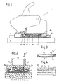
- FIG. 1 shows a safety ski binding according to the invention in longitudinal section and FIG. 2 shows the binding in cross section. 3 and 4, the longitudinal section and the bottom view of the spring cage are shown.
- FIGS. 1 and 2 A safety ski binding is shown in FIGS. 1 and 2.
- a guide rail 2 On the top of a ski 1, a guide rail 2 is fastened by means of screws, not shown, on which a binding body 3 is displaceably guided in the longitudinal direction of the ski 1 and in a manner known per se for adapting the binding to differently long ski boots in the desired position by means of a Adjustment catch 4 can be determined.
- the binding body 3 has a pressing device which consists of two pressing springs 5 in a spring cage 6 having two side walls 6e, and is displaceable against the force of the pressing springs 5 on the guide rail 2, the pressing springs 5 between a shoulder 3a of the binding body 3 and the rear Wall 6a of the spring cage 6 are clamped.
- the spring cage 6 is made of plastic and has in the middle part of its bottom 6b a longitudinal web 6c, which is formed by two elongated recesses 6d in the bottom 6b in a resiliently convex manner.
- the web of the spring cage 6 thus forms a resilient element 6c.
- the side walls 6e of the spring cage 6 come into contact with the binding body 3 along the surface 3b and also push it up until it lies against the rail surfaces 2a and has no more play in the guide rail 2.
- the Binding body 3 pushed up front and back down.
- the binding body 3 is in a somewhat inclined position relative to the guide rail 2, viewed in the longitudinal direction of the ski, the resilient element 6c being deformed. This deformation, however, is negligible compared to the frictional forces that arise during an adjustment of the binding body 3 during ski deflections, so that a compensation of ski deflections can take place practically without negative influences by the spring element 6c.
Description
Die Erfindung bezieht sich auf eine Sicherheitsskibindung nach dem Oberbegriff des Patentanspruches 1.The invention relates to a safety ski binding according to the preamble of
Eine Sicherheitsskibindung mit einer elastischen Anpreßeinrichtung, die auch eine Kompensation eines Spiels zwischen Bindungskörper und Führungsschiene in Höhenrichtung ermöglicht, ist in der DE-A-30 15 478 beschrieben. Bei dieser Ausführung weist der Bindungskörper in seinem unteren Bereich eine Schrägfläche auf, die sich mit einer Schrägfläche der Verstellraste, mit der die Stellung des Bindungskörpers auf der Führungsschiene festgelegt wird, unter dem Einfluß mindestens einer in Skilängsrichtung wirkenden Anpreßfeder in Anlage befindet, wenn kein Skischuh in die Bindung eingespannt ist. Die Schrägflächen sind dabei so ausgestaltet, daß sie unter dem Einfluß der Anpreßfeder eine Kraftkomponente nach oben ergeben, die den Bindungskörper in der Führungsschiene in die Höhe drückt, solange bis kein Spiel mehr vorhanden ist. In dieser Lage ist somit der Bindungskörper relativ zur Führungsschiene durch Kraftschluß in Position gehalten. Bei eingesetztem Skischuh, d.h. in belastetem Zustand, wird jedoch der Bindungskörper gegen die Kraft der Anpreßfeder nach hinten verschoben, wodurch zwischen der Verstellraste und dem Bindungskörper, in Skilängsrichtung betrachtet, ein Freiraum entsteht. Dadurch wird aber die an den beiden Schrägflächen wirkende Kraft aufgehoben und es entsteht zwischen Bindungskörper und Führungsschiene das eingangs erwähnte Spiel. Nun kann der Bindungskörper bei Skidurchbiegungen gegen die Kraft der Anpreßfeder realtiv zur Verstellraste in bekannter Weise nach hinten verschoben werden.DE-A-30 15 478 describes a safety ski binding with an elastic pressing device, which also enables compensation of play between the binding body and the guide rail in the vertical direction. In this embodiment, the binding body has an inclined surface in its lower region, which is in contact with an inclined surface of the adjustment catch, with which the position of the binding body on the guide rail is determined, under the influence of at least one pressure spring acting in the longitudinal direction of the ski, if no ski boot is clamped in the binding. The inclined surfaces are designed in such a way that under the influence of the pressure spring they result in a force component that pushes the binding body upwards in the guide rail until there is no more play. In this position, the binding body is thus held in position relative to the guide rail by frictional connection. With the ski boot inserted, i.e. in the loaded state, however, the binding body is pushed back against the force of the pressure spring, which creates a space between the adjustment catch and the binding body, viewed in the longitudinal direction of the ski. As a result, however, the force acting on the two inclined surfaces is canceled and the game mentioned at the outset arises between the binding body and the guide rail. Now the binding body in ski deflections against the force of the pressure spring can be realistically moved to the adjustment catch in a known manner to the rear.
Aus der FR-A-2,495.479 ist zwar schon bekannt, in der Grundplatte eines Vorderbackens einen von einer Feder beaufschlagten Kolben anzuordnen, welcher Kolben gegen die Kraft der Feder in Höhenrichtung verschiebbar ist. Diese bekannte Vorrichtung ist jedoch als eine Hilfseinrichtung zur Festlegung der jeweils gewünschten Lage der Verstellraste und wirkt zu diesem Zweck mit an der Führungsschiene in Skilängsrichtung in Abständen vorgesehenen, als Raststellen ausgebildeten Hohlräumen zusammen. Die Verrastung selbst erfolgt jedoch mittels eines Stellbolzens, welcher an seinem unteren Endbereich eine in der Form eines Exzenters ausgebildete Raste trägt, die mit, in Skilängsrichtung ebenfalls in Abständen vorgesehenen, Raststellen in und von diesen außer Eingriff bringbar ist. Des weiteren ist zwischen dem Zylinderkörper der Verstellraste und der Aufnahmestelle in der Grundplatte für diese Verstellraste ein elastisches Element eingesetzt, durch welche seitlich eine elastische Abstützung zwischen Aufnahmestelle und Verstellraste herbeigeführt werden soll.From FR-A-2,495,479 it is already known to arrange a piston acted upon by a spring in the base plate of a front jaw, which piston can be displaced in the height direction against the force of the spring. However, this known device is used as an auxiliary device for fixing the respectively desired position of the adjustment catch and for this purpose interacts with cavities provided on the guide rail in the longitudinal direction of the ski at intervals and designed as catch points. However, the locking itself takes place by means of an adjusting bolt, which carries at its lower end region a catch which is designed in the form of an eccentric and which can be brought into and out of engagement with and at these locking points, which are also provided at intervals in the longitudinal direction of the ski. Furthermore, an elastic element is inserted between the cylinder body of the adjusting catch and the receiving point in the base plate for this adjusting catch, by means of which an elastic support between the receiving point and the adjusting catch is to be brought about laterally.
Eine Maßnahme, die Grundplatte des Bindungskörpers in der Führungsschiene unter den Einfluß mindestens einer in Skilängsrichtung wirkenden Anpreßfeder zu setzen, wie dies sowohl bei der erstgenannten bekannten Lösung als auch beim Gegenstand der Erfindung der Fall ist, kann dieser Offenbarung nicht entnommen werden. Auch eine Kraftkomponente, welche bei nicht eingesetztem Skischuh ein in Höhenrichtung vorhandenes Spiel zwischen dem Bindungskörper und der Führungsschiene aufheben würde, ist bei dieser Ausgestaltung nicht erkennbar; die den Kolben beaufschlagende Feder dient, wie bereits erwähnt wurde, lediglich der Positionierung des Bindungskörpers über seine Grundplatte realtiv zur Führungsschiene. Hinsichtlich der Größe der Kraft der dem Kolben beaufschlagenden Feder ist in der letztgenannten Druckschrift keine Aussage enthalten. Aus diesem Grund kann auch nicht angenommen werden, daß hiebei ein Aufheben eines zwischen dem Bindungskörper und dessen Führungsschiene vorhandenen Spiels erfolgen sollte. Dies um so weniger, als beide behandelte druckschriftliche Veröffentlichungen von der selben Anmelderin stammen und zum Zeitpunkt der Hinterlegung der letztgenannten FR-OS die erstgenannte DE-OS bereits veröffentlicht war.A measure of placing the base plate of the binding body in the guide rail under the influence of at least one pressure spring acting in the longitudinal direction of the ski, as is the case both in the first known solution and in the subject matter of the invention, cannot be inferred from this disclosure. A force component, which would cancel any play in the vertical direction between the binding body and the guide rail, would not be discernible in this embodiment; As already mentioned, the spring acting on the piston merely serves to position the binding body via its base plate in relation to the guide rail. With regard to the magnitude of the force of the spring acting on the piston, there is no statement in the latter publication. For this reason, it cannot be assumed that a game existing between the binding body and its guide rail should be canceled. This is all the less the case since both of the printed publications dealt with come from the same applicant and when the latter FR-OS was deposited, the first-mentioned DE-OS was already published.
Die Erfindung hat sich die Aufgabe gestellt, eine Sicherheitsskibindung der eingangs genannten Art zu schaffen, die das Spiel zwischen Bindungskörper und Führungsschiene auf andere Weise kompensiert.The invention has for its object to provide a safety ski binding of the type mentioned, which compensates for the game between the binding body and the guide rail in a different way.
Erreicht wird das gesetzte Ziel erfindungsgemäß durch die im Anspruch 1 enthaltenen kennzeichnenden Merkmale.The set goal is achieved according to the invention by the characterizing features contained in
Durch die erfindungsgemäßen Maßnahmen wird der Bindungskörper über die Seitenwände des Federkäfigs mit der Kraft dessen federnden Elementes nach oben gedrückt, bis der Bindungskörper in Höhenrichtung kein Spiel mehr in der Führungsschiene hat. Auf sehr einfache Weise wird so das Spiel des Bindungskörpers in der Führungsschiene kompensiert, solange sich dieser im unbelasteten Zustand befindet. Bei eingesetztem Skischuh wird, wie bei Bindungen dieser Art allgemein bekannt, der Bindungskörper durch die Sohle des Skischuhs an seiner Vorderseite nach oben und an seiner Hinterseite nach unten gedrückt. Dadurch nehmen derartige Bindungskörper realtiv zur Skioberseite eine etwas geneigte Lage ein, wodurch bei Skidurchbiegungen die Anpreßfedern auch die entstehenden erhöhten Reibungskräfte zu überwinden haben. Während eines solchen Verstellvorganges wird auch das federnde Element deformiert. Durch diese Deformation wird zwar die während einer Skidurchbiegung entstehende Reibungskraft zusätzlich erhöht, diese ist jedoch den ohnehin auftretenden Reibungskräften gegenüber, die die Anpreßfedern zu überwinden haben, vernachlässigbar. Somit kann durch die erfindungsgemäßen Maßnahmen ein Verstellen des Bindungskörpers gegen die Kraft der Anpreßfeder bei Skidurchbiegungen ohne Entstehen von nennenswerten zusätzlichen Reibungskräften erfolgen.By means of the measures according to the invention, the binding body is pressed upward over the side walls of the spring cage with the force of its resilient element until the binding body no longer has any play in the guide rail in the vertical direction. The play of the binding body in the guide rail is compensated in a very simple way as long as it is in the unloaded state. When a ski boot is inserted, as is generally known in bindings of this type, the binding body is pressed upwards by the sole of the ski boot on its front side and downwards on its rear side. As a result, such binding bodies realistically assume a somewhat inclined position with respect to the top of the ski, as a result of which the pressure springs also have to overcome the resulting increased frictional forces in the event of ski deflections. During such an adjustment process, the resilient element is also deformed. Although this deformation increases the frictional force that arises during a ski deflection, it is negligible compared to the frictional forces that have to be overcome by the pressure springs. Thus, the measures according to the invention can be used to adjust the binding body against the force of the pressure spring during ski deflections without generating any significant additional frictional forces.
Durch die Merkmale des Anspruches 2 kann das federnde Element durch zwei langgestreckte Aussparungen im Boden des Federkäfigs hergestellt werden. Dadurch wird der Wasserabfluß erleichtert und es verringert sich auch das Gewicht des Federkäfigs.Due to the features of
Die Merkmale des Anspruches 3 ermöglichen die Verwendung einer den jeweiligen Erfordernissen angepaßte Federform.The features of
Weitere Merkmale, Vorteile und Einzelheiten der Erfindung werden nun anhand der Zeichnung näher beschrieben. Es zeigen die Fig.1 eine erfindungsgemäße Sicherheitsskibindung im Längsschnitt und die Fig.2 die Bindung im Querschnitt. In den Fig.3 und 4 sind der Längsschnitt und die Untersicht des Federkäfigs dargestellt.Further features, advantages and details of the invention will now be described with reference to the drawing. 1 shows a safety ski binding according to the invention in longitudinal section and FIG. 2 shows the binding in cross section. 3 and 4, the longitudinal section and the bottom view of the spring cage are shown.
In den Fig.1 und 2 ist eine Sicherheitsskibindung dargestellt. Auf der Oberseite eines Ski 1 ist mittels nicht dargestellter Schrauben eine Führungsschiene 2 befestigt, auf welcher ein Bindungskörper 3 in der Längsrichtung des Ski 1 verschiebbar geführt und in an sich bekannter Weise zur Anpassung der Bindung an unterschiedlich lange Skischuhe in der jeweils gewünschten Lage mittels einer Verstellraste 4 festlegbar ist. Der Bindungskörper 3 besitzt eine Anpreßeinrichtung, die aus zwei Anpreßfedern 5 in einem zwei Seitenwände 6e aufweisenden Federkäfig 6 besteht, und ist gegen die Kraft der Anpreßfedern 5 auf der Führungsschiene 2 verschiebbar, wobei die Anpreßfedern 5 zwischen einem Ansatz 3a des Bindungskörpers 3 und der rückwärtigen Wand 6a des Federkäfigs 6 eingespannt sind. Der Federkäfig 6 ist aus Kunststoff und weist im mittleren Teil seines Bodens 6b einen in Längsrichtung verlaufenden Steg 6c auf, der durch zwei langgestreckte Aussparungen 6d im Boden 6b federnd nach unten hin konvex ausgebildet ist. Der Steg des Federkäfigs 6 bildet somit ein federndes Element 6c.A safety ski binding is shown in FIGS. 1 and 2. On the top of a
Schiebt man den Bindungskörper 3 mit seiner Anpreßeinrichtung auf die Führungsschiene 2 auf, so wird der nach unten hin konvexe, als federndes Element 6c wirksame Steg des Federkäfigs 6 und damit auch der Federkäfig 6 selbst hochgedrückt. Die Seitenwände 6e des Federkäfigs 6 kommen entlang der Fläche 3b in Kontakt mit dem Bindungskörper 3 und drücken diesen ebenfalls hoch, solange bis dieser entlang den Schienenflächen 2a anliegt und kein Spiel mehr in der Führungsschiene 2 hat. Bei eingesetztem Skischuh wird der Bindungskörper 3 vorne nach oben und hinten nach unten gedrückt. Dadurch nimmt der Bindungskörper 3 realtiv zur Führungsschiene 2, in Skilängsrichtung betrachtet, eine etwas geneigte Lage ein, wobei das federnde Element 6c deformiert wird. Diese Deformation ist jedoch gegenüber jener Reibungskräfte, die während eines Verstellens des Bindungskörpers 3 bei Skidurchbiegungen entstehen, vernachlässigbar, so daß ein Ausgleich von Skidurchbiegungen praktisch ohne negative Einflüsse durch das Federelement 6c vor sich gehen kann.If you push the
Die Erfindung ist auf die dargestellten Ausführungsbeispiele nicht eingeschränkt.The invention is not restricted to the exemplary embodiments shown.
Claims (3)
- A safety ski binding comprising a mounting body mounted in a guide rail for displacement in the longitudinal direction of a ski and adapted to be locked at different positions by means of an adjustable detent, said mounting body being subjected to the action of at least one biasing spring acting in the longitudinal direction of the ski and provided with means for the compensation of a play existing in the up and down direction between said mounting body and said guide rail, characterized in that said bisaing spring (5) is retained in a spring cage (6) having two sidewalls (6e), the bottom (6b) of said spring cage (6) being provided with a downwards acting resilient element (6c) acting through said sidewalls (6e) of said spring cage (6) on said mounting body (3) for biasing it upwards into engagement with said guide rail (2) in the no-load state, and that in the loaded state, i.e. when a ski boot is inserted, said mounting body (3) assumes, as viewed in the longitudinal direction of the ski, a front-to-rear inclined position relative to said guide rail (2) to result in said resilient element (6c) being deformed.
- A safety ski binding according to claim 1, characterized in that said spring cage (6) is integrally made of a resilient material, preferably a plastic material, said resilient element being formed as a rib (6c) extending along an intermediate portion of said bottom (6b) in the longitudinal direction and having a convex lower surface.
- A safety ski binding according to claim 1, characterized in that said resilient element is formed by at least one separate spring, preferably a leaf spring, provided on the underside of the spring cage bottom.
Applications Claiming Priority (2)
| Application Number | Priority Date | Filing Date | Title |
|---|---|---|---|
| AT3423/87 | 1987-12-23 | ||
| AT0342387A AT388877B (en) | 1987-12-23 | 1987-12-23 | SAFETY SKI BINDING |
Publications (3)
| Publication Number | Publication Date |
|---|---|
| EP0321687A2 EP0321687A2 (en) | 1989-06-28 |
| EP0321687A3 EP0321687A3 (en) | 1990-01-03 |
| EP0321687B1 true EP0321687B1 (en) | 1991-12-27 |
Family
ID=3550297
Family Applications (1)
| Application Number | Title | Priority Date | Filing Date |
|---|---|---|---|
| EP88118465A Expired - Lifetime EP0321687B1 (en) | 1987-12-23 | 1988-11-05 | Safety ski binding |
Country Status (3)
| Country | Link |
|---|---|
| EP (1) | EP0321687B1 (en) |
| AT (1) | AT388877B (en) |
| DE (1) | DE3867219D1 (en) |
Families Citing this family (4)
| Publication number | Priority date | Publication date | Assignee | Title |
|---|---|---|---|---|
| AT395538B (en) * | 1990-10-12 | 1993-01-25 | Tyrolia Freizeitgeraete | DEVICE FOR ADJUSTING THE LENGTH OF HEEL HOLDERS |
| AT399821B (en) * | 1992-10-29 | 1995-07-25 | Tyrolia Freizeitgeraete | SOLE SUPPORT PLATE |
| AT399287B (en) * | 1992-10-29 | 1995-04-25 | Tyrolia Freizeitgeraete | SOLE SUPPORT PLATE |
| AT414100B (en) * | 2002-10-28 | 2006-09-15 | Tyrolia Technology Gmbh | IN THE CONSTRUCTION OF A SLIDING BOARD, IN PARTICULAR A SKIS, INTEGRATED GUIDANCE AND SLIDING BOARD, IN PARTICULAR SKI |
Family Cites Families (4)
| Publication number | Priority date | Publication date | Assignee | Title |
|---|---|---|---|---|
| DE2429610C3 (en) * | 1974-06-20 | 1982-07-22 | Geze Gmbh, 7250 Leonberg | Safety ski bindings |
| FR2454822A1 (en) * | 1979-04-26 | 1980-11-21 | Salomon & Fils F | SECURITY FIXING FOR SKI |
| FR2495479A1 (en) * | 1980-12-10 | 1982-06-11 | Salomon & Fils F | DEVICE FOR ADJUSTING THE LONGITUDINAL POSITION OF A SAFETY FIXATION FOR SKI |
| DE3523058C2 (en) * | 1985-06-27 | 1993-11-04 | Marker Deutschland Gmbh | LENGTH ADJUSTABLE SAFETY SKI BINDING |
-
1987
- 1987-12-23 AT AT0342387A patent/AT388877B/en active
-
1988
- 1988-11-05 EP EP88118465A patent/EP0321687B1/en not_active Expired - Lifetime
- 1988-11-05 DE DE8888118465T patent/DE3867219D1/en not_active Expired - Fee Related
Also Published As
| Publication number | Publication date |
|---|---|
| DE3867219D1 (en) | 1992-02-06 |
| EP0321687A2 (en) | 1989-06-28 |
| AT388877B (en) | 1989-09-11 |
| ATA342387A (en) | 1989-02-15 |
| EP0321687A3 (en) | 1990-01-03 |
Similar Documents
| Publication | Publication Date | Title |
|---|---|---|
| DE2739207A1 (en) | SKI BOOT ELEMENT | |
| WO1988004562A1 (en) | Adjusting system for ski bindings | |
| DE3541079A1 (en) | LOW FRICTION SELF-LOCKING ADJUSTMENT | |
| DD238726A5 (en) | GUIDANCE APPARATUS OF A SHOE, AND SHOE AND SURFACE ADJUSTED TO THIS DEVICE | |
| DE2066178C2 (en) | Safety binding for holding a boot on a ski | |
| DE4010118A1 (en) | BINDING DEVICE OF A PAIR OF SHOES OF A SKIER ON A SLIDING BOARD ON SNOW | |
| EP0321687B1 (en) | Safety ski binding | |
| DE19500268C1 (en) | Height-adjusting device for safety belt in motor vehicles | |
| DD239338A5 (en) | SIDE GUIDE DEVICE OF AN SKI SHOE, AND TO THIS DEVICE ATTACHED SHOE AND CROSS-COAST SKI | |
| EP0098515B1 (en) | Device for changing the longitudinal position of ski bindings | |
| DE2448769C2 (en) | Holding device for safety ski bindings | |
| DE4040383C2 (en) | Alpine safety ski binding | |
| DE2910508A1 (en) | SAFETY BINDING FOR SKI | |
| EP0466860B1 (en) | Ski binding parts, in particular toepieces | |
| DE3838586C2 (en) | Lateral guiding device of a shoe on a cross-country ski | |
| CH653265A5 (en) | ADJUSTMENT FOR BAKING. | |
| DE2600858B2 (en) | Ski safety binding with a step plate releasably connected to the shoe | |
| AT390887B (en) | SAFETY SKI BINDING | |
| DE7723442U1 (en) | ADJUSTABLE HINGE ARM OF A DOOR OR FURNITURE HINGE | |
| WO1987007516A2 (en) | Safety ski binding | |
| DE3526298A1 (en) | Shoe, in particular sports shoe with exchangeable outsole part | |
| AT400404B (en) | MOUNTING DEVICE FOR A SKI BINDING | |
| DE3934877A1 (en) | TIE TO KEEP THE FRONT END OF A SHOE ON A CROSS-COUNTRY SKI | |
| EP0033957A1 (en) | Ski-binding for cross-country skiing | |
| DE3007608C2 (en) | Device for holding objects |
Legal Events
| Date | Code | Title | Description |
|---|---|---|---|
| PUAI | Public reference made under article 153(3) epc to a published international application that has entered the european phase |
Free format text: ORIGINAL CODE: 0009012 |
|
| AK | Designated contracting states |
Kind code of ref document: A2 Designated state(s): CH DE FR LI |
|
| RHK1 | Main classification (correction) |
Ipc: A63C 9/00 |
|
| RIN1 | Information on inventor provided before grant (corrected) |
Inventor name: ERDEI, ROLAND Inventor name: LUSCHNIG, FRANZ Inventor name: STRITZL, KARL Inventor name: WUERTHNER, HUBERT |
|
| PUAL | Search report despatched |
Free format text: ORIGINAL CODE: 0009013 |
|
| AK | Designated contracting states |
Kind code of ref document: A3 Designated state(s): CH DE FR LI |
|
| 17P | Request for examination filed |
Effective date: 19900117 |
|
| 17Q | First examination report despatched |
Effective date: 19910612 |
|
| RAP1 | Party data changed (applicant data changed or rights of an application transferred) |
Owner name: TMC CORPORATION |
|
| GRAA | (expected) grant |
Free format text: ORIGINAL CODE: 0009210 |
|
| AK | Designated contracting states |
Kind code of ref document: B1 Designated state(s): CH DE FR LI |
|
| REF | Corresponds to: |
Ref document number: 3867219 Country of ref document: DE Date of ref document: 19920206 |
|
| ET | Fr: translation filed | ||
| PLBE | No opposition filed within time limit |
Free format text: ORIGINAL CODE: 0009261 |
|
| STAA | Information on the status of an ep patent application or granted ep patent |
Free format text: STATUS: NO OPPOSITION FILED WITHIN TIME LIMIT |
|
| REG | Reference to a national code |
Ref country code: CH Ref legal event code: PUE Owner name: HTM SPORT- UND FREIZEITGERAETE GMBH |
|
| RAP2 | Party data changed (patent owner data changed or rights of a patent transferred) |
Owner name: HTM SPORT- UND FREIZEITGERAETE GESELLSCHAFT M.B.H. |
|
| 26N | No opposition filed | ||
| REG | Reference to a national code |
Ref country code: FR Ref legal event code: TP |
|
| REG | Reference to a national code |
Ref country code: CH Ref legal event code: PFA Free format text: HTM SPORT- UND FREIZEITGERAETE AKTIENGESELLSCHAFT |
|
| REG | Reference to a national code |
Ref country code: FR Ref legal event code: CJ |
|
| PGFP | Annual fee paid to national office [announced via postgrant information from national office to epo] |
Ref country code: FR Payment date: 19941005 Year of fee payment: 7 Ref country code: DE Payment date: 19941005 Year of fee payment: 7 |
|
| PGFP | Annual fee paid to national office [announced via postgrant information from national office to epo] |
Ref country code: CH Payment date: 19941129 Year of fee payment: 7 |
|
| PG25 | Lapsed in a contracting state [announced via postgrant information from national office to epo] |
Ref country code: LI Effective date: 19951130 Ref country code: CH Effective date: 19951130 |
|
| REG | Reference to a national code |
Ref country code: CH Ref legal event code: PL |
|
| PG25 | Lapsed in a contracting state [announced via postgrant information from national office to epo] |
Ref country code: FR Effective date: 19960731 |
|
| PG25 | Lapsed in a contracting state [announced via postgrant information from national office to epo] |
Ref country code: DE Effective date: 19960801 |
|
| REG | Reference to a national code |
Ref country code: FR Ref legal event code: ST |