EP0321642B1 - Coke oven door with a metal shield - Google Patents
Coke oven door with a metal shield Download PDFInfo
- Publication number
- EP0321642B1 EP0321642B1 EP88109176A EP88109176A EP0321642B1 EP 0321642 B1 EP0321642 B1 EP 0321642B1 EP 88109176 A EP88109176 A EP 88109176A EP 88109176 A EP88109176 A EP 88109176A EP 0321642 B1 EP0321642 B1 EP 0321642B1
- Authority
- EP
- European Patent Office
- Prior art keywords
- bars
- strips
- elements
- sealing element
- fastening elements
- Prior art date
- Legal status (The legal status is an assumption and is not a legal conclusion. Google has not performed a legal analysis and makes no representation as to the accuracy of the status listed.)
- Expired - Lifetime
Links
- 229910052751 metal Inorganic materials 0.000 title claims description 14
- 239000002184 metal Substances 0.000 title claims description 14
- 239000000571 coke Substances 0.000 title claims description 12
- 238000007789 sealing Methods 0.000 claims description 25
- 239000007787 solid Substances 0.000 claims 1
- 238000010276 construction Methods 0.000 description 15
- 230000005540 biological transmission Effects 0.000 description 9
- 229910000831 Steel Inorganic materials 0.000 description 7
- 239000010959 steel Substances 0.000 description 7
- 239000000725 suspension Substances 0.000 description 6
- PXHVJJICTQNCMI-UHFFFAOYSA-N Nickel Chemical compound [Ni] PXHVJJICTQNCMI-UHFFFAOYSA-N 0.000 description 2
- 239000000956 alloy Substances 0.000 description 2
- 229910045601 alloy Inorganic materials 0.000 description 2
- 238000005452 bending Methods 0.000 description 2
- 230000008642 heat stress Effects 0.000 description 2
- 239000000463 material Substances 0.000 description 2
- 239000007769 metal material Substances 0.000 description 2
- 230000000704 physical effect Effects 0.000 description 2
- VYZAMTAEIAYCRO-UHFFFAOYSA-N Chromium Chemical compound [Cr] VYZAMTAEIAYCRO-UHFFFAOYSA-N 0.000 description 1
- RTAQQCXQSZGOHL-UHFFFAOYSA-N Titanium Chemical compound [Ti] RTAQQCXQSZGOHL-UHFFFAOYSA-N 0.000 description 1
- 229910052782 aluminium Inorganic materials 0.000 description 1
- XAGFODPZIPBFFR-UHFFFAOYSA-N aluminium Chemical compound [Al] XAGFODPZIPBFFR-UHFFFAOYSA-N 0.000 description 1
- 239000000919 ceramic Substances 0.000 description 1
- 229910052804 chromium Inorganic materials 0.000 description 1
- 239000011651 chromium Substances 0.000 description 1
- 210000000078 claw Anatomy 0.000 description 1
- 239000003245 coal Substances 0.000 description 1
- 238000004939 coking Methods 0.000 description 1
- 238000011161 development Methods 0.000 description 1
- 230000018109 developmental process Effects 0.000 description 1
- 238000009826 distribution Methods 0.000 description 1
- 238000010438 heat treatment Methods 0.000 description 1
- 238000009413 insulation Methods 0.000 description 1
- 238000004519 manufacturing process Methods 0.000 description 1
- 238000000034 method Methods 0.000 description 1
- 229910052759 nickel Inorganic materials 0.000 description 1
- 230000008092 positive effect Effects 0.000 description 1
- 238000003825 pressing Methods 0.000 description 1
- 230000001681 protective effect Effects 0.000 description 1
- 229910052710 silicon Inorganic materials 0.000 description 1
- 239000010703 silicon Substances 0.000 description 1
- 230000003068 static effect Effects 0.000 description 1
- 239000004575 stone Substances 0.000 description 1
- 230000035882 stress Effects 0.000 description 1
- 239000010936 titanium Substances 0.000 description 1
- 229910052719 titanium Inorganic materials 0.000 description 1
Images


Classifications
-
- C—CHEMISTRY; METALLURGY
- C10—PETROLEUM, GAS OR COKE INDUSTRIES; TECHNICAL GASES CONTAINING CARBON MONOXIDE; FUELS; LUBRICANTS; PEAT
- C10B—DESTRUCTIVE DISTILLATION OF CARBONACEOUS MATERIALS FOR PRODUCTION OF GAS, COKE, TAR, OR SIMILAR MATERIALS
- C10B25/00—Doors or closures for coke ovens
- C10B25/02—Doors; Door frames
- C10B25/06—Doors; Door frames for ovens with horizontal chambers
Definitions
- the invention relates to a coke oven door, consisting of a hollow profile frame for receiving pressure elements and fastening elements, a sealing unit with an outer sealing element and an inner sealing element and a metal plate assigned to the inner sealing element.
- Such a coke oven door is known from DE 34 40 312 Al.
- the metal plate consists of several large-sized sheet metal sections arranged one above the other, each sheet plate section consisting of several sheet metal sheets arranged one behind the other from shaped profiles. It is disadvantageous that the large-sized metal sheets tend to deform as a result of heat stress.
- the invention is also based on this object.
- the metal plate is composed of a plurality of individual bars or strips or strips or grids arranged one above the other or next to one another, which are connected to the inner sealing element serving as a supporting element in a tension-free manner via fastening elements.
- the support according to the invention is effected by a one-part or multi-part door box which is arranged behind the bars or strips or the grille.
- the rods according to the invention can have a full profile or can be formed by a hollow profile.
- the cross-sectional shape of the bars can be square, rectangular or round. Irregularly shaped cross sections are also conceivable.
- the bars have a thickness of 10 to 30 mm. Bands differ from the bars by a significantly smaller thickness, namely 4 to 10 mm, and by a larger width, namely up to 100 mm.
- the bars or strips can run transversely to the longitudinal direction of the door or in the longitudinal direction of the door.
- Fastening elements are optionally provided according to the invention for fastening, which cover the strips or bars transversely to their longitudinal direction.
- Such fasteners can in turn be formed by bands that are hinged to the back of the support or extend to the rest of the door body.
- Thinner rods are also suitable as fastening elements, which reach into the rods forming the actual metal shield through corresponding openings.
- the fastening elements can also be arranged laterally and have recesses into which the rods and / or strips are inserted in the longitudinal direction or into which the rods or strips are inserted from the front transversely to their longitudinal direction.
- the individual rods or strips can also be suspended individually or in groups from the support.
- the groups preferably have a height of 200 to 400 mm in the case of bars or strips running transversely to the longitudinal direction of the door.
- these groups also correspond to elements of the box forming the support. These elements of the box forming the support then have the same overall height as the groups of bars or strips. Slits are preferably provided between the elements of the box forming the support. The slots are said to allow the entry of raw gas during the coking process.
- Figures 5 to 8 show different mounting options for a metal plate made of rods.
- the coke oven door consists of a power transmission unit 1 and a sealing unit 21.
- the power transmission unit 1 is formed in Fig. 2 as a hollow profile frame 24, the longitudinal spars in Fig. 3 with 22 and the cross bars in Fig. 3 with 23.
- the longitudinal bars 22 are open at the upper and lower ends. Furthermore, there are 4 openings in the longitudinal spars at the junctures to the transverse spars, so that heating air in the hollow profile frame 24 unhindered from the transverse spars 23 into the longitudinal spars 22 and flow up there and can emerge from the hollow profile frame 24 at the top.
- the hollow profile frame 24 shown in the exemplary embodiment according to FIG. 2 is provided with a multiplicity of pressure elements 28 which are rotatable in themselves.
- these pressure elements 28 are composed of a movable sleeve 5, a spindle 3 fixedly connected to the sleeve 5 and a sprocket 2 fixedly attached to the spindle 3.
- the spindle 3 is rotatably guided in a threaded sleeve 4 .
- the threaded sleeve 4 according to Fig. 3 is firmly welded into the hollow profile frame 24 according to Fig. 2.
- bolts 7 are welded to the outer flanks of the longitudinal spars 22 according to Fig. 3 and to the chamber frame 28 Fig. 3 adjustable hooks for receiving the bolts 7 attached.
- the number of hooks 8 depends on the number of bolts 7 and is 6.
- the number of bolts 7 depends on the furnace height. With a furnace height of 4 m, a total of 4 bolts are sufficient, in the arrangement of 2 at the top and bottom of the hollow profile frame 24 according to Fig. 2.
- the pressing forces of the individual elements 28 according to Fig. 2 on the sealing unit 21 according to Fig. 3 is generated by a rotating chain hoist 27 according to Fig. 2. With this arrangement there is thus a constant distribution of forces guaranteed via the power transmission unit 1 according to Fig. 2 to the sealing unit 21 according to Fig. 3.
- the pivot point 30 according to FIG. 2 for moving the circulating chain 27 according to FIG. 2 can be transferred to each pressure element 28.
- the torque required for point 30 is generated by a torque motor, which is not shown in the figure. This torque motor can be installed both directly on the power transmission unit 1 and on door operating machines which are present during operation.
- the square hollow profile frame 24 shown in the exemplary embodiment according to FIG. 3 can be replaced by the choice of other profiles.
- Geometries of commercially available profiles such as rectangular hollow profiles, U profiles, L profiles, double T profiles, tubular profiles and simple flat profiles allow the pressure elements 28 to be accommodated.
- the sealing unit 21 consists of the sealing element 9 and an insulation 29.
- the sealing element 9 forms a hollow body with the element 10.
- Both elements 9 and 10 are made of a heat-resistant metallic material.
- a thickness of between 2 and 4 mm per sealing element is provided. The overall height of the furnace and its width have no influence on the thickness, since the restoring forces of the furnace filling do not differ significantly from one another in common furnace sizes.
- the elements 9 and 10 have the same profile according to Fig. 3 and are firmly connected to each other. A loose arrangement of element 10 on element 9 is feasible.
- the hollow body formed by the elements 9 and 10 can, on the one hand, be designed as closed and, on the other hand, can be made open via the element 10 towards the interior of the open.
- the element 10 is formed with lateral slits or is open at the top and bottom in the vertical direction. This results in the possibility of expanding the two gas channels, formed by the shield construction 11 according to FIG. 3 and the side surfaces of the element 10, in order to expand the gas channel formed by the hollow body.
- the gas channel is expanded by up to 100%. This expansion of the gas channel has a very positive effect on the static pressure behavior in the channel and therefore on the tightness of the door.
- Fig. 1 the usual door foot does not apply to the door.
- the inner element 10 according to Fig. 3 takes over the function of a door foot 35 due to its design.
- a metal U-seal 14 is provided as an exemplary embodiment between the free leg 31 according to FIG. 3 and the sealing surface of the door frame.
- the sealing unit 21 is held loosely by the power transmission unit 1 in the exposed state via brackets 12 and 25. In the inserted state, the brackets 12 and 25 become ineffective, so that the different rotational capacity due to the different temperature positions of the sealing unit 21 and the power transmission unit 1 is taken into account.
- cross bars 34 are arranged between the bars 22. These cross bars serve as a lifting point of attack for the claws present on the door lifting machines, which are not shown in the drawings.
- the "heat shield” 33 no longer consists, as usual, of flat, one-piece, heat-resistant metallic plates of different designs, but instead of a multiplicity of heat-resistant metallic round bars 11 of the same cross section _ arranged transversely to the furnace chamber _ in front of the inner screed 10 according to FIG. 3 loosely attached via breakpoints 32.
- the individual round bars between 20 and 30 mm thick are drilled through at two points to accommodate the suspension.
- a level surface is created over the furnace height to accommodate the coal front when filling the coke oven.
- the individual rods 11 and the suspensions 32 behave more dimensionally stable at high temperatures, since both each rod can expand freely in the transverse direction to the furnace and the suspension rods can extend freely in the vertical direction to the furnace.
- other geometries of the rod construction with the same physical properties can be integrated, such as square, rectangular and strip-like shapes.
- the one-piece rod construction according to Figs. 1 and 3 can also be carried out as a multi-part construction over the height of the inner screed 10. Furthermore, the rod construction also allows a rod guide in the vertical direction, not shown in the drawings. Here, the Bars guided in parallel as a continuous unit, held with cross bars distributed over the height.
- the leveling door 36 according to Fig. 1 and 4 is designed in a circular construction.
- the leveling box 14 designed as a tube according to Figure 4 takes up the sealing surface 15.
- a metallic cover 16 is pressed in front of this sealing surface 15 via the force transmission frame 17 via bolts or springs 39.
- the fixed points 19 and 20 become effective.
- the fixed point 19 is designed as a hinge in order to pivot the leveling door 36.
- the fixed point 20 is effective via a handwheel 37 with a spindle which is mounted in the joint 38.
- each group has an overall height of 300 mm in the exemplary embodiment. All bars have a round cross-section.
- the rod diameter is 20 mm.
- the bars labeled 50 there are drilled through, so that a 10 mm thick wire or bar can be passed through the individual bars 50 and bent over.
- the individual rods 50 are held together by the rod designated 51.
- the rods 50 can be hung on the rod 51 at the same time.
- the suspension is otherwise the same as for the individual rods according to FIG. 1.
- dash-dotted line 52 indicates the support line through elements 10.
- Figure 6 shows rods 60 with a round cross-section and 15 mm in diameter.
- the rods 60 are held in side plates 61.
- the sheets 61 are provided with bores into which the rods 60 are inserted in the longitudinal direction.
- the rods 60 form with the sheets 61 elements which are hung on hooks 62.
- the embodiment according to Figure 8 differs from that according to Figure 6 in that the rods are not inserted in the longitudinal direction but are inserted transversely to their longitudinal direction from the front into sheets 80 which have hook-shaped depressions 82 for the rods denoted by 81.
Landscapes
- Chemical & Material Sciences (AREA)
- Engineering & Computer Science (AREA)
- Materials Engineering (AREA)
- Oil, Petroleum & Natural Gas (AREA)
- Organic Chemistry (AREA)
- Coke Industry (AREA)
Description
Die Erfindung betrifft eine Koksofentür, bestehend aus einem Hohlprofilrahmen zur Aufnahme von Andruckelementen und Befestigungselementen, einer Dichtungseinheit mit einem äußeren Dichtelement und einem inneren Dichtelement sowie einem dem inneren Dichtelement zugeordneten Metallschild.The invention relates to a coke oven door, consisting of a hollow profile frame for receiving pressure elements and fastening elements, a sealing unit with an outer sealing element and an inner sealing element and a metal plate assigned to the inner sealing element.
Eine solche Koksofentür ist aus der DE 34 40 312 Al bekannt. Der Metallschild besteht dabei aus mehreren großformatigen übereinander angeordneten Blechtafelschüssen, wobei jeder Blechtafelschuß aus mehreren hintereinander angeordneten Blechtafeln aus Formprofilen besteht. Nachteilig ist, daß die großformatigen Blechtafeln infolge von Hitzespannungen zu Verformungen neigen.Such a coke oven door is known from DE 34 40 312 Al. The metal plate consists of several large-sized sheet metal sections arranged one above the other, each sheet plate section consisting of several sheet metal sheets arranged one behind the other from shaped profiles. It is disadvantageous that the large-sized metal sheets tend to deform as a result of heat stress.
Weiterhin ist es aus der gattungsfremden DE-C-35 28 511 bekannt, das innere Dichtelement einer Koksofentür aus mehrteiligen U-förmigen metallischen Profilblechen zu bilden, deren große Formate beim Auftreten von Hitzespannungen ebenfalls zu Verformungen neigen.Furthermore, it is known from the non-generic DE-C-35 28 511 to form the inner sealing element of a coke oven door from multi-part U-shaped metallic profiled sheets, the large formats of which also tend to deform when heat stresses occur.
Während nach der Jahrhundertwende noch Vorschläge zur Verwendung von Stahlschilden an Koksofentüren bekannt geworden sind, haben sich in dieser Zeit und auch später Metallschilde in der Praxis nicht etablieren können. Das ist relativ einfach mit dem seinerzeit zur Verfügung stehenden Material erklärbar. Stahlschilde, die unmittelbar mit dem heißen Koks Berührung erlangen, erfahren dabei eine Erwärmung von deutlich mehr als 1000 Grad. Stähle mit der notwendigen Hitzebeständigkeit sind erst in neuerer Zeit verfügbar. Derartige Stähle sind hochlegierte Stähle. Die Legierungsanteile sind Chrom und/oder Aluminium und/oder Nickel und/oder Silizium und/oder Titan. Vor etwa 8 Jahren begannen die ersten Versuche. Diese Versuche basierten auf einer Nachbildung eines keramischen Stopfens mit Hilfe von Platten aus hochhitzebeständigem Stahl. Zunächst hat sich das jedoch als ungeeignet gezeigt. Die Stahlkonstruktion ist deshalb auf einen Schild beschränkt worden. Der Schild bestand aus einzelnen sich überlappenden Blechen. Auch die Bleche zeigen noch eine erhebliche Verformung. Es sind deshalb verschiedene Alternativen mit dem Ziel der Schaffung eines praxisgerechten Teilschildes mit langer Standzeit gemacht worden.While proposals for the use of steel shields on coke oven doors were still known after the turn of the century, metal shields could not be established in practice at this time and also later. This can be explained relatively easily with the material available at the time. Steel shields that come into direct contact with the hot coke experience a temperature rise of significantly more than 1000 degrees. Steels with the necessary heat resistance have only recently become available. Such steels are high-alloy steels. The alloy components are chromium and / or aluminum and / or nickel and / or silicon and / or Titanium. The first attempts began about 8 years ago. These tests were based on a replica of a ceramic stopper using plates made of high-temperature steel. At first, however, this turned out to be unsuitable. The steel structure has therefore been limited to one sign. The sign consisted of individual overlapping sheets. The sheets also show considerable deformation. Various alternatives have therefore been made with the aim of creating a practical part label with a long service life.
Der Erfindung liegt gleichfalls diese Aufgabe zugrunde.The invention is also based on this object.
Nach der Erfindung wird die Lösung dieser Aufgabe dadurch erreicht, daß der Metallschild aus einer Mehrzahl von einzelnen übereinander oder nebeneinander angeordneten Stäben oder Bändern oder aus Gittern zusammengesetzt ist, die mit dem als Abstützelement dienenden inneren Dichtelement über Befestigungselemente spannungsfrei ausdehnbar verbunden sind.According to the invention, the solution to this problem is achieved in that the metal plate is composed of a plurality of individual bars or strips or strips or grids arranged one above the other or next to one another, which are connected to the inner sealing element serving as a supporting element in a tension-free manner via fastening elements.
Während eine Vielzahl anderer Entwicklungen eine andere Richtung geht, nämlich in die eines sich einteilig über die Höhe der Koksofentür erstreckenden Schildes geht, geht die Erfindung in die genau entgegengesetzte Richtung, nämlich in die Verringerung der Abmessungen. Die damit gegebene Befürchtung, bei so extremen Abmessungen, wie sie durch Stäbe, Bänder und Gitter gegeben sind, würde sich auch eine extreme Wärmeverformung einstellen, hat sich nicht bewahrheitet. Das wird darauf zurückgeführt, daß die Stäbe, Bänder und Gitter möglichst weitgehend auf ihrer Länge gestützt werden. Bei den anderen bekannten Lösungsvorschlägen ist eine solche Abstützung nicht gegeben. Vielmehr sind die bekannten anderen Schilde auf eine Zwei-Punkte-Auflage bzw. Zwei-Linien-Auflage angewiesen. Zwischen diesen Linien werden diese Schilde ganz erheblich auf Biegung beansprucht.While a host of others Developments take a different direction, namely in which a sign extends in one piece over the height of the coke oven door, the invention goes in the opposite direction, namely in the reduction in dimensions. The fear that this would give, with dimensions as extreme as those given by bars, strips and grids, would also result in extreme heat deformation, has not materialized. This is attributed to the fact that the bars, strips and grids are supported as much as possible over their length. Such support is not provided in the other known solutions. Rather, the known other shields rely on a two-point support or two-line support. Between these lines, these shields are subjected to considerable bending stress.
Die erfindungsgemäße Abstützung wird durch einen ein- oder mehrteiligen Türkasten bewirkt, der hinter den Stäben oder Bändern oder dem Gitter angeordnet ist.The support according to the invention is effected by a one-part or multi-part door box which is arranged behind the bars or strips or the grille.
Die erfindungsgemäßen Stäbe können ein Vollprofil besitzen oder durch ein Hohlprofil gebildet werden. Die Querschnittsform der Stäbe kann quadratisch oder rechteckig oder rund sein. Es sind auch unregelmäßig geformte Querschnitte denkbar.The rods according to the invention can have a full profile or can be formed by a hollow profile. The cross-sectional shape of the bars can be square, rectangular or round. Irregularly shaped cross sections are also conceivable.
Die Stäbe haben eine Dicke von 10 bis 30 mm. Bänder unterscheiden sich von den Stäben durch eine deutlich geringere Dicke, nämlich 4 bis 10 mm, und durch eine größere Breite, nämlich bis zu 100 mm. Die Stäbe oder Bänder können quer zur Türlängsrichtung oder in Türlängsrichtung verlaufen. Zur Befestigung sind wahlweise nach der Erfindung Befestigungselemente vorgesehen, die die Bänder oder Stäbe quer zu deren Längsrichtung überfassen. Solche Befestigungselemente können ihrerseits durch Bänder gebildet werden, die rückwärtig an der Abstützung angelenkt sind oder bis zum übrigen Türkörper reichen.The bars have a thickness of 10 to 30 mm. Bands differ from the bars by a significantly smaller thickness, namely 4 to 10 mm, and by a larger width, namely up to 100 mm. The bars or strips can run transversely to the longitudinal direction of the door or in the longitudinal direction of the door. Fastening elements are optionally provided according to the invention for fastening, which cover the strips or bars transversely to their longitudinal direction. Such fasteners can in turn be formed by bands that are hinged to the back of the support or extend to the rest of the door body.
Als Befestigungselemente eignen sich auch dünnere Stäbe, die durch entsprechende Öffnungen in die den eigentlichen Metallschild bildenden Stäben greifen. Die Befestigungselemente können auch seitlich angeordnet sein und Ausnehmungen aufweisen, in die die Stäbe und/oder Bänder in Längsrichtung eingeschoben werden oder in die die Stäbe oder Bänder quer zu ihrer Längsrichtung von vorne eingelegt werden.Thinner rods are also suitable as fastening elements, which reach into the rods forming the actual metal shield through corresponding openings. The fastening elements can also be arranged laterally and have recesses into which the rods and / or strips are inserted in the longitudinal direction or into which the rods or strips are inserted from the front transversely to their longitudinal direction.
Die einzelnen Stäbe oder Bänder können auch einzeln oder zu mehreren an der Abstüzung aufgehängt sein.The individual rods or strips can also be suspended individually or in groups from the support.
Vorteilhaft ist es, die Stäbe und Bänder zu Gruppen zusammenzufassen, vorzugsweise haben die Gruppen bei quer zur Türlängsrichtung verlaufenden Stäben oder Bändern in Türlängsrichtung eine Höhe von 200 bis 400 mm. Wahlweise korrespondieren diese Gruppen auch mit Elementen des die Abstützung bildenden Kastens. Diese Elemente des die Abstützung bildenden Kastens haben dann die gleiche Bauhöhe wie die Gruppen von Stäben oder Bändern. Zwischen den Elementen des die Abstützung bildenden Kastens sind vorzugsweise Schlitze vorgesehen. Die Schlitze sollen den Eintritt von Rohgas während des Verkokungsvorganges ermöglichen.It is advantageous to combine the bars and strips into groups; the groups preferably have a height of 200 to 400 mm in the case of bars or strips running transversely to the longitudinal direction of the door. Optionally, these groups also correspond to elements of the box forming the support. These elements of the box forming the support then have the same overall height as the groups of bars or strips. Slits are preferably provided between the elements of the box forming the support. The slots are said to allow the entry of raw gas during the coking process.
Die Zeichnung zeigt verschiedene Ausführungsbeispiele der Erfindung.
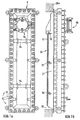
- Abb. 1 eine erfindungsgemäße Koksofentür im Schnitt während des Ofenbetriebes in Schließstellung am Kammerrahmen,
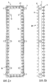
- Abb. 2 eine Darstellung des Hohlprofilrahmens mit den integrierten automatisch drehbaren Andruckelementen einschließlich Kettenräder und Kettenzug,
- Abb. 3 eine vergrößerte Darstellung eines Horizontalschnittes.
- Abb. 4 eine vergrößerte Darstellung eines Horizontalschnittes entlang einer Schnittlinie im Bereich der Planiertür einschließlich Planierkasten.
- Fig. 1 a coke oven door according to the invention in section during furnace operation in the closed position on the chamber frame,
- Fig. 2 shows the hollow profile frame with the integrated, automatically rotatable pressure elements including chain wheels and chain hoist,
- Fig. 3 is an enlarged view of a horizontal section.
- Fig. 4 is an enlarged view of a horizontal section along a section line in the area of the leveling door including the leveling box.
Die Abbildungen 5 bis 8 zeigen verschiedene Befestigungsmöglichkeiten für ein Metallschild aus Stäben.Figures 5 to 8 show different mounting options for a metal plate made of rods.
Nach Abb. 1 besteht die erfindungsgemäße Koksofentür aus einer Kraftübertragungseinheit 1 und einer Dichtungseinheit 21. Die Kraftübertragungseinheit 1 ist in Abb. 2 als Hohlprofilrahmen 24 ausgebildet, dessen Längsholme in Abb. 3 mit 22 und dessen Querholme in Abb. 3 mit 23 bezeichnet sind. Die Längsholme 22 sind am oberen und unteren Ende offen. Ferner befinden sich in den Längsholmen an den Verbindungsstellen zu den Querholmen 4 Öffnungen, so daß sich im Hohlprofilrahmen 24 erwärmende Luft ungehindert aus den Querholmen 23 in die Längsholme 22 und dort nach oben strömen und oben aus dem Hohlprofilrahmen 24 austreten kann.According to Fig. 1, the coke oven door according to the invention consists of a
Der im Ausführungsbeispiel nach Abb. 2 dargestellte Hohlprofilrahmen 24 ist mit einer Vielzahl von Andruckelementen 28 versehen, die in sich drehbar sind. Diese Andruckelemente 28 setzen sich nach Abb. 3 zusammen aus einer beweglichen Hülse 5, einer mit der Hülse 5 fest verbundenen Spindel 3 und einem auf der Spindel 3 fest angebrachtem Kettenrad 2. Nach Abb. 3 wird die Spindel 3 in einer Gewindehülse 4 drehbar geführt. Die Gewindehülse 4 nach Abb. 3 ist in dem Hohlprofilrahmen 24 nach Abb. 2 fest eingeschweißt.The
Die Kraftübertragung von den Andruckelementen 28 über den Kettenzug 27 nach Abb. 2 auf die Dichtungseinheit 21 nach Abb. 3 erfolgt nach Abb. 3 über Federn 6 oder Bolzen 6, die in der drehbaren Hülse 5 nach Abb. 3 untergebracht sind. Um eine kraftschlüssige Verbindung einerseits zwischen Kammerrahmen 28 nach Abb. 3, Dichtungseinheit 21 nach Abb. 3 und andererseits zwischen Kraftübertragungseinheit 1 nach Abb. 3 zu erreichen, sind an den Außenflanken der Längsholme 22 nach Abb. 3 Bolzen 7 angeschweißt und am Kammerrahmen 28 nach Abb. 3 verstellbare Haken zur Aufnahme der Bolzen 7 angebracht. Die Anzahl der Haken 8, richtet sich nach der Anzahl der Bolzen 7, beträgt 6. Die Anzahl der Bolzen 7 ist abhängig von der Ofenhöhe. Bei einer Ofenhöhe von 4 m reichen insgesamt 4 Bolzen aus, und zwar in der Anordnung von je 2 oben und unten am Hohlprofilrahmen 24 nach Abb. 2.The force transmission from the
Die Andruckkräfte der einzelnen Elemente 28 nach Abb. 2 auf die Dichtungseinheit 21 nach Abb. 3 wird durch einen umlaufenden Kettenzug 27 nach Abb. 2 erzeugt. Mit dieser Anordnung ist somit eine konstante Kräfteverteilung über die Kraftübertragungseinheit 1 nach Abb. 2 auf die Dichtungseinheit 21 nach Abb. 3 gewährleistet. Der Drehpunkt 30 nach Abb. 2 zum Bewegen der umlaufenden Kette 27 nach Abb. 2 ist auf jedes Andruckelement 28 übertragbar. Das zu benötigende Drehmoment für den Punkt 30 wird durch einen Drehmomentenmotor, der in der Abb. nicht dargestellt ist, erzeugt. Dieser Drehmomentenmotor kann sowohl direkt auf der Kraftübertragungseinheit 1 als auch auf im Betrieb vorhandenen Türbedienungsmaschinen installiert werden.The pressing forces of the
Der im Ausführungsbeispiel nach Abb. 3 dargestellte quadratische Hohlprofilrahmen 24 ist durch die Wahl anderer Profile ersetzbar. Geometrien von handelsüblichen Profilen wie rechteckiges Hohlprofil, U-Profil, L-Profile, Doppel-T-Profile, Rohrprofile und einfaches Flachprofil lassen eine Unterbringung der Andruckelemente 28 zu.The square
Nach Abb. 3 besteht die Dichtungseinheit 21 aus dem Dichtelement 9 und einer Isolierung 29. Das Dichtelement 9 bildet mit dem Element 10 einen Hohlkörper. Beide Elemente 9 und 10 bestehen aus einem hitzebeständigen metallischen Material. Je nach Profilierung ist eine Stärke pro Dichtlement zwischen 2 und 4 mm vorgesehen. Die Bauhöhe des Ofens und seine Breite haben auf die Stärke keinen Einfluß, da die Rückstellkräfte der Ofenfüllung bei gebräuchlichen Ofengrößen nicht wesentlich voneinander abweichen.According to Fig. 3, the sealing
Die Elemente 9 und 10 besitzen nach Abb. 3 die gleiche Profilierung und sind untereinander fest verbunden. Eine lose Anordnung des Elementes 10 an Element 9 ist ausführbar.The
Der von den Elementen 9 und 10 gebildete Hohlkörper kann zum einen als geschlossen und zum anderen zum Offeninneren hin über das Element 10 offen ausgebildet werden. Im letzteren Fall wird das Element 10 mit seitlichen Schlitzen oder in vertikaler Richtung oben und unten offen ausgebildet. Hierdurch ergibt sich die Möglichkeit, die beiden Gaskanäle, gebildet durch die Schildkonstruktion 11 nach Abb. 3 und den Seitenflächen des Elementes 10, um den durch den Hohlkörper gebildeten Gaskanal zu erweitern. Gegenüber üblichen Türkonstruktionen mit Schildbauweise anstelle von Steinstopfen ergibt sich eine Gaskanalerweiterung um bis zu 100 %. Diese Erweiterung des Gaskanals wirkt sich sehr positiv auf das statische Druckverhalten im Kanal und mithin auf die Dichtigkeit der Tür aus.The hollow body formed by the
Nach Abb. 1 fällt bei der Tür der übliche Türfuß fort. Das innere Element 10 nach Abb. 3 übernimmt aufgrund seiner konstruktiven Ausbildung die Funktion eines Türfußes 35.According to Fig. 1, the usual door foot does not apply to the door. The
Zwischen dem freien Schenkel 31 nach Abb. 3 und der Dichtfläche des Türrahmens ist als Ausführungsbeispiel eine metallische U-Dichtung 14 vorgesehen.A metal U-seal 14 is provided as an exemplary embodiment between the
Die Dichtungseinheit 21 wird im ausgesetzten Zustand lose über Halterungen 12 und 25 von der Kraftübertragungseinheit 1 gehalten. Im eingesetzten Zustand werden die Halterungen 12 und 25 wirkungslos, so daß dem unterschiedlichen Drehnvermögen aufgrund der unterschiedlichen Temperaturlagen von Dichtungseinheit 21 und Kraftübertragungseinheit 1 Rechnung getragen wird.The sealing
Zum Ein- und Aussetzen der Tür mittels der Türabhebemaschine sind zwischen den Holmen 22 zwei Querstäbe 34 angeordnet. Diese Querstäbe dienen als Hebeangriffspunkt für die an den Türabhebemaschinen vorhandenen Klauen, die in den Zeichnungen nicht dargestellt sind.To insert and remove the door by means of the door lifting machine, two
Nach Abbildung 1 und 3 besteht das erfindungsgemäße "Hitzeschild" 33 nicht mehr wie üblich aus ebenen einteiligen hitzebeständigen metallischen Platten unterschiedlicher Bauformen, sondern aus einer Vielzahl von hitzebeständigen metallischen Rundstäben 11 gleichen Querschnitts _ quer zur Ofenkammer angeordnet _ vor der inneren Bohle 10 nach Abb. 3 lose über Haltepunkte 32 befestigt. Die einzelnen Rundstäbe zwischen 20 und 30 mm stark sind zur Aufnahme der Aufhängung an zwei Stellen durchbohrt. Durch Aufeinanderreihen der Einzelstäbe auf die Aufhängungen ebenfalls als Rundstäbe ausgeführt, wird über die Ofenhöhe eine eben durchgehende Fläche zur Aufnahme der Kohlefront beim Füllen des Koksofens erzeugt. Die Einzelstäbe 11 als auch die Aufhängungen 32 verhalten sich wegen ihrer einfachen Geometrie bei hohen Temperaturen formstabiler, da sich sowohl jeder Stab in Querrichtung zum Ofen als auch die Aufhängestäbe in vertikaler Richtung zum Ofen frei dehnen können. Bei den Ausführungsformen der Stäbe sind andere Geometrien der Stabbauweise mit gleichen physikalischen Eigenschaften integrierbar, wie quadratische, rechteckige und streifenförmige Formen.According to Figures 1 and 3, the "heat shield" 33 according to the invention no longer consists, as usual, of flat, one-piece, heat-resistant metallic plates of different designs, but instead of a multiplicity of heat-resistant metallic round bars 11 of the same cross section _ arranged transversely to the furnace chamber _ in front of the
Die einteilige Stabbauweise nach Abb. 1 und 3 ist auch als mehrteilige Konstruktion über die Höhe der inneren Bohle 10 ausführbar. Weiterhin läßt die Stabbauweise auch eine Stabführung in vertikaler Richtung, in den Zeichnungen nicht dargestellt, zu. Hierbei werden die Stäbe parallel geführt als durchgehende Einheit, mit über die Höhe verteilte Querstäbe gehalten.The one-piece rod construction according to Figs. 1 and 3 can also be carried out as a multi-part construction over the height of the
Die Planiertür 36 nach Abb. 1 und 4 ist in Rundbauweise ausgeführt. Der als Rohr ausgebildete Planierkasten 14 nach Abbildung 4 nimmt die Dichtfläche 15 auf. Vor diese Dichtfläche 15 wird ein metallischer Deckel 16 über den Kraftübertragungsrahmen 17 über Bolzen oder Federn 39 angedrückt. Bei Wirksamwerden der Krafteinleitung über den Rahmen 17 über Kettenräder 20 und Kettenzug 18 werden die Festpunkte 19 und 20 wirksam. Der Festpunkt 19 ist als Schanier ausgelegt, um die Planiertür 36 zu schwenken. Der Festpunkt 20 wird über ein Handrad 37 mit einer Spindel, die im Gelenk 38 gelagert ist, wirksam.The leveling
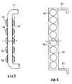
Nach Abbildung 5 bis 8 sind anstelle der Stäbe 11 andere Stäbe vorgesehen, die in Gruppen zusammengefaßt sind. Jede Gruppe hat eine Bauhöhe von im Ausführungsbeispiel 300 mm. Alle Stäbe haben runden Querschnitt.According to Figures 5 to 8 11 other rods are provided instead of the rods, which are combined in groups. Each group has an overall height of 300 mm in the exemplary embodiment. All bars have a round cross-section.
Im Ausführungsbeispiel nach Abbildung 5 ist der Stabdurchmesser 20 mm. Zur Aufhängung sind die dort mit 50 bezeichneten Stäbe durchbohrt, so daß ein 10 mm dicker Draht bzw. Stab durch die Einzelstäbe 50 durchgeführt und umgebogen werden kann. Von den mit 51 bezeichneten Stab werden die Einzelstäbe 50 zusammengehalten. An dem Stab 51 können die Stäbe 50 zugleich aufgehängt werden. Die Aufhängung ist im übrigen die gleiche wie bei den Einzelstäben nach Figur 1.In the exemplary embodiment according to Figure 5, the rod diameter is 20 mm. For the suspension, the bars labeled 50 there are drilled through, so that a 10 mm thick wire or bar can be passed through the
In Abbildung 5 kennzeichnet die strichpunktierte Linie 52 die Stützlinie durch die Elemente 10.In Figure 5, dash-dotted
Abbildung 6 zeigt Stäbe 60 mit rundem Querschnitt und 15 mm Durchmesser. Die Stäbe 60 werden in seitlichen Blechen 61 gehalten. Dazu sind die Bleche 61 mit Bohrungen versehen, in die die Stäbe 60 in Längsrichtung eingeschoben werden. Die Stäbe 60 bilden mit den Blechen 61 Elemente, die an Haken 62 aufgehängt werden.Figure 6 shows
Das Ausführungsbeispiel nach Abbildung 8 unterscheidet sich von dem nach Abbildung 6 dadurch, daß die Stäbe nicht in Längsrichtung eingeschoben sondern quer zu ihrer Längsrichtung von vorn in Bleche 80 eingelegt werden, die für die mit 81 bezeichneten Stäbe hakenförmige Vertiefungen 82 besitzen.The embodiment according to Figure 8 differs from that according to Figure 6 in that the rods are not inserted in the longitudinal direction but are inserted transversely to their longitudinal direction from the front into
Nach Abbildung 7 sind die dort mit 70 bezeichneten Stäbe mit Bändern 71 gehalten.According to Figure 7, the bars marked there with 70 are held with
Allen Stäben ist gemeinsam, daß sie lose untereinanderhängen, hierdurch wird erreicht,
- daß im Vergleich zu den bisher bekannten ebenso einteiligen Schutzschilden aus hitzebeständigem metallischen Material durch die Formgebung eine sehr viel höhere Formstabilität auch bei den üblichen hohen Koksofentemperaturen erzielt wird,
- daß die Rundstabbauweise keine Schweißkonstruktion darstellt.
- daß andere Geometrien der Stabbauweise mit gleichen physikalischen Eigenschaften ausführbar sind, z.B. quadratische, rechteckige oder geometrische Formen,
- daß die Stäbe handelsübliche Profile darstellen,
- daß die einteilige Stabbauweise auch eine Stabführung in vertikaler Richtung, über die Höhe parallel zur inneren Bohle gesehen, zuläßt.
- daß die Stärken der Stäbe erheblich dünner ausführbar sind, so daß bei genügender Biegesteifigkeit das erfindungsgemäße "Schild" insgesamt leichter wird als bekannte ebene einteilige Plattenausführungen und
- daß aufgrund der leichten Bauweise und der problemlosen Fertigung die Konstruktion sich kostengünstiger als die üblichen Bauweisen darstellt.
- that compared to the previously known one-piece protective shields made of heat-resistant metallic material, the shape gives a much higher dimensional stability even at the usual high coke oven temperatures,
- that the round bar construction is not a welded construction.
- that other geometries of the rod construction can be implemented with the same physical properties, for example square, rectangular or geometric shapes,
- that the bars represent commercial profiles,
- that the one-piece rod construction also permits rod guidance in the vertical direction, seen parallel to the inner screed over the height.
- that the strengths of the bars can be made considerably thinner, so that the "shield" according to the invention becomes lighter overall than known flat one-piece plate designs and with sufficient bending rigidity
- that due to the light construction and the trouble-free manufacture, the construction is cheaper than the usual construction.
Claims (13)
Applications Claiming Priority (2)
| Application Number | Priority Date | Filing Date | Title |
|---|---|---|---|
| DE19873743156 DE3743156A1 (en) | 1987-08-03 | 1987-12-19 | COOKING OVEN DOOR WITH METAL PLATE |
| DE3743156 | 1987-12-19 |
Publications (2)
| Publication Number | Publication Date |
|---|---|
| EP0321642A1 EP0321642A1 (en) | 1989-06-28 |
| EP0321642B1 true EP0321642B1 (en) | 1991-04-24 |
Family
ID=6343018
Family Applications (1)
| Application Number | Title | Priority Date | Filing Date |
|---|---|---|---|
| EP88109176A Expired - Lifetime EP0321642B1 (en) | 1987-12-19 | 1988-06-09 | Coke oven door with a metal shield |
Country Status (2)
| Country | Link |
|---|---|
| EP (1) | EP0321642B1 (en) |
| DE (1) | DE3862579D1 (en) |
Family Cites Families (2)
| Publication number | Priority date | Publication date | Assignee | Title |
|---|---|---|---|---|
| DE3440312A1 (en) * | 1984-01-05 | 1985-07-25 | Ruhrkohle Ag, 4300 Essen | Guard shield for a coke-oven door |
| DE3528511C1 (en) * | 1985-08-08 | 1986-08-14 | Carl Still Gmbh & Co Kg, 4350 Recklinghausen | Lightweight coke oven door |
-
1988
- 1988-06-09 EP EP88109176A patent/EP0321642B1/en not_active Expired - Lifetime
- 1988-06-09 DE DE8888109176T patent/DE3862579D1/en not_active Expired - Lifetime
Also Published As
| Publication number | Publication date |
|---|---|
| DE3862579D1 (en) | 1991-05-29 |
| EP0321642A1 (en) | 1989-06-28 |
Similar Documents
| Publication | Publication Date | Title |
|---|---|---|
| EP0291701B1 (en) | Charge preheater for preheating the charge of a metallurgical melting installation | |
| DE2742877B2 (en) | Heat exchanger, especially recuperator for high temperature reactors | |
| EP0317494B1 (en) | Coke oven door with a ceramic shield construction | |
| EP0321642B1 (en) | Coke oven door with a metal shield | |
| DE3743156A1 (en) | COOKING OVEN DOOR WITH METAL PLATE | |
| DE2436334C2 (en) | Process for heating billets in lifting transport furnaces and lifting transport furnace for carrying out the process | |
| EP0058320B1 (en) | Process for the coking of coal and coke oven for carrying out the process | |
| DE4029010C1 (en) | ||
| EP0063700A2 (en) | Method of sealing doors of horizontal coke ovens and coke ovens with coke oven doors | |
| EP0321640B1 (en) | Coke oven door with a shield construction | |
| DE3327337A1 (en) | Coke oven doors for horizontal chamber coking ovens | |
| DE2929322C2 (en) | Heating furnace | |
| DE3344976A1 (en) | LIGHTWEIGHT COOKING DOOR | |
| DE3505551C2 (en) | Coke oven door with a ceramic stopper | |
| EP0383813B1 (en) | Chamber frame | |
| EP0114183B1 (en) | Door for coke oven with horizontal chambers | |
| EP0084366B2 (en) | Coke oven chamber door | |
| DE1758785C3 (en) | Refractory casing for support members of heat treatment furnaces | |
| DE3348043C2 (en) | Coke oven door with sheet pile | |
| DE3147918C1 (en) | Container lining, which can be subjected to high-temperature stress | |
| AT204580B (en) | Melting or heating furnace, especially for metals | |
| DE2807612A1 (en) | HEAT EXCHANGER | |
| DE3743157A1 (en) | Coke oven door with shield construction | |
| DE8128278U1 (en) | COOKING OVEN DOOR | |
| DE8201167U1 (en) | Coke oven door |
Legal Events
| Date | Code | Title | Description |
|---|---|---|---|
| PUAI | Public reference made under article 153(3) epc to a published international application that has entered the european phase |
Free format text: ORIGINAL CODE: 0009012 |
|
| AK | Designated contracting states |
Kind code of ref document: A1 Designated state(s): BE DE FR GB IT NL |
|
| 17P | Request for examination filed |
Effective date: 19890509 |
|
| 17Q | First examination report despatched |
Effective date: 19900220 |
|
| ITF | It: translation for a ep patent filed | ||
| GRAA | (expected) grant |
Free format text: ORIGINAL CODE: 0009210 |
|
| AK | Designated contracting states |
Kind code of ref document: B1 Designated state(s): BE DE FR GB IT NL |
|
| REF | Corresponds to: |
Ref document number: 3862579 Country of ref document: DE Date of ref document: 19910529 |
|
| GBT | Gb: translation of ep patent filed (gb section 77(6)(a)/1977) | ||
| ET | Fr: translation filed | ||
| PLBE | No opposition filed within time limit |
Free format text: ORIGINAL CODE: 0009261 |
|
| STAA | Information on the status of an ep patent application or granted ep patent |
Free format text: STATUS: NO OPPOSITION FILED WITHIN TIME LIMIT |
|
| 26N | No opposition filed | ||
| PGFP | Annual fee paid to national office [announced via postgrant information from national office to epo] |
Ref country code: FR Payment date: 19930512 Year of fee payment: 6 |
|
| PGFP | Annual fee paid to national office [announced via postgrant information from national office to epo] |
Ref country code: GB Payment date: 19930519 Year of fee payment: 6 |
|
| PGFP | Annual fee paid to national office [announced via postgrant information from national office to epo] |
Ref country code: BE Payment date: 19930527 Year of fee payment: 6 |
|
| PGFP | Annual fee paid to national office [announced via postgrant information from national office to epo] |
Ref country code: NL Payment date: 19930630 Year of fee payment: 6 |
|
| PGFP | Annual fee paid to national office [announced via postgrant information from national office to epo] |
Ref country code: DE Payment date: 19940112 Year of fee payment: 6 |
|
| PG25 | Lapsed in a contracting state [announced via postgrant information from national office to epo] |
Ref country code: GB Effective date: 19940609 |
|
| PG25 | Lapsed in a contracting state [announced via postgrant information from national office to epo] |
Ref country code: BE Effective date: 19940630 |
|
| BERE | Be: lapsed |
Owner name: RUHRKOHLE A.G. Effective date: 19940630 |
|
| PG25 | Lapsed in a contracting state [announced via postgrant information from national office to epo] |
Ref country code: NL Effective date: 19950101 |
|
| GBPC | Gb: european patent ceased through non-payment of renewal fee |
Effective date: 19940609 |
|
| NLV4 | Nl: lapsed or anulled due to non-payment of the annual fee | ||
| PG25 | Lapsed in a contracting state [announced via postgrant information from national office to epo] |
Ref country code: FR Effective date: 19950228 |
|
| PG25 | Lapsed in a contracting state [announced via postgrant information from national office to epo] |
Ref country code: DE Effective date: 19950301 |
|
| REG | Reference to a national code |
Ref country code: FR Ref legal event code: ST |
|
| PG25 | Lapsed in a contracting state [announced via postgrant information from national office to epo] |
Ref country code: IT Free format text: LAPSE BECAUSE OF NON-PAYMENT OF DUE FEES Effective date: 20050609 |