EP0321617A1 - Cap with visor and pivotable eye shield - Google Patents
Cap with visor and pivotable eye shield Download PDFInfo
- Publication number
- EP0321617A1 EP0321617A1 EP87311327A EP87311327A EP0321617A1 EP 0321617 A1 EP0321617 A1 EP 0321617A1 EP 87311327 A EP87311327 A EP 87311327A EP 87311327 A EP87311327 A EP 87311327A EP 0321617 A1 EP0321617 A1 EP 0321617A1
- Authority
- EP
- European Patent Office
- Prior art keywords
- visor
- eye shield
- mounting block
- cap according
- cap
- Prior art date
- Legal status (The legal status is an assumption and is not a legal conclusion. Google has not performed a legal analysis and makes no representation as to the accuracy of the status listed.)
- Granted
Links
Images

Classifications
-
- A—HUMAN NECESSITIES
- A42—HEADWEAR
- A42B—HATS; HEAD COVERINGS
- A42B1/00—Hats; Caps; Hoods
- A42B1/24—Hats; Caps; Hoods with means for attaching articles thereto, e.g. memorandum tablets or mirrors
- A42B1/247—Means for attaching eyewear
-
- A—HUMAN NECESSITIES
- A61—MEDICAL OR VETERINARY SCIENCE; HYGIENE
- A61F—FILTERS IMPLANTABLE INTO BLOOD VESSELS; PROSTHESES; DEVICES PROVIDING PATENCY TO, OR PREVENTING COLLAPSING OF, TUBULAR STRUCTURES OF THE BODY, e.g. STENTS; ORTHOPAEDIC, NURSING OR CONTRACEPTIVE DEVICES; FOMENTATION; TREATMENT OR PROTECTION OF EYES OR EARS; BANDAGES, DRESSINGS OR ABSORBENT PADS; FIRST-AID KITS
- A61F9/00—Methods or devices for treatment of the eyes; Devices for putting-in contact lenses; Devices to correct squinting; Apparatus to guide the blind; Protective devices for the eyes, carried on the body or in the hand
- A61F9/02—Goggles
- A61F9/025—Special attachment of screens, e.g. hinged, removable; Roll-up protective layers
-
- A—HUMAN NECESSITIES
- A61—MEDICAL OR VETERINARY SCIENCE; HYGIENE
- A61F—FILTERS IMPLANTABLE INTO BLOOD VESSELS; PROSTHESES; DEVICES PROVIDING PATENCY TO, OR PREVENTING COLLAPSING OF, TUBULAR STRUCTURES OF THE BODY, e.g. STENTS; ORTHOPAEDIC, NURSING OR CONTRACEPTIVE DEVICES; FOMENTATION; TREATMENT OR PROTECTION OF EYES OR EARS; BANDAGES, DRESSINGS OR ABSORBENT PADS; FIRST-AID KITS
- A61F9/00—Methods or devices for treatment of the eyes; Devices for putting-in contact lenses; Devices to correct squinting; Apparatus to guide the blind; Protective devices for the eyes, carried on the body or in the hand
- A61F9/04—Eye-masks ; Devices to be worn on the face, not intended for looking through; Eye-pads for sunbathing
- A61F9/045—Eye-shades or visors; Shields beside, between or below the eyes
-
- G—PHYSICS
- G02—OPTICS
- G02C—SPECTACLES; SUNGLASSES OR GOGGLES INSOFAR AS THEY HAVE THE SAME FEATURES AS SPECTACLES; CONTACT LENSES
- G02C3/00—Special supporting arrangements for lens assemblies or monocles
- G02C3/02—Arrangements for supporting by headgear
Landscapes
- Health & Medical Sciences (AREA)
- Ophthalmology & Optometry (AREA)
- General Health & Medical Sciences (AREA)
- Physics & Mathematics (AREA)
- Heart & Thoracic Surgery (AREA)
- Vascular Medicine (AREA)
- Life Sciences & Earth Sciences (AREA)
- Animal Behavior & Ethology (AREA)
- Engineering & Computer Science (AREA)
- Public Health (AREA)
- Veterinary Medicine (AREA)
- Biomedical Technology (AREA)
- General Physics & Mathematics (AREA)
- Optics & Photonics (AREA)
- Helmets And Other Head Coverings (AREA)
- Eyeglasses (AREA)
- Vehicle Step Arrangements And Article Storage (AREA)
- Pivots And Pivotal Connections (AREA)
- Walking Sticks, Umbrellas, And Fans (AREA)
Abstract
Description
- The present invention relates to a cap provided with a visor, such a cap being known as a visor cap, and more particularly to a visor cap provided with a pivotable eye shield.
- It is perhaps well known that many people who perform outdoor activities always use an eye shield such as sun glasses or goggles for protection to avoid dust from getting into the eyes and also wear a cap or hat with a visor for shading the eyes.
- In the past, a number of devices have been proposed for attaching eye glasses to the visor of a cap, such as is disclosed in U.S. 4,541,125 in which a clip part attaches the main eye glasses part to a cap visor whereby the eye glasses part is pivotally movable between operative and inoperative positions, with other devices having been disclosed in U.S. 4,304,005 and U.S. 4,636,048.
- It is an object of the present invention to provide a visor cap having a pivotable eye shield which cannot only be angularly adjusted but can be moved back and forth to adjust the distance thereof from the eyes.
- According to the present invention, a visor cap comprises a cap body secured to a forwardly projecting visor which supports a pivotally movable eye shield, characterised in that the eye shield is pivotally secured to a mounting block, which is reciprocally supported by the visor to allow back and forth adjustment as well as angular adjustment of the eye shield.
- A visor cap in accordance with the present invention is not only useful but is considered to be stylish.
- Preferably, the attachment between the visor and the mounting block includes a groove for facilitating said reciprocable adjustment. In a preferred embodiment, a lower portion of the visor is formed as a dovetail groove open at its rear and an upper portion of the mounting block is formed of complementary trapezoidal shape for sliding frictional engagement in said dovetail groove.
- Preferably, the eye shield is detachably secured to the mounting block. In a preferred embodiment, a lower portion of the mounting block is formed with a transversely extending retaining channel accessible through a narrower opening and an upper portion of the eye shield is formed with a transversely extending mounting shaft to be snap inserted through said narrower opening for pivoting frictional engagement in said retaining channel. More particularly, the eye shield includes a pair of upstanding legs whose upper ends are connected by the mounting shaft, the mounting block including a pair of slots extending in planes perpendicular to the mounting shaft for receiving respective ones of said legs.
- The visor may be formed of a non-opaque plastics material whose rear edge is secured to the cap body, the mounting block may be formed of a resiliently deformable plastics material and the eye shield may be formed of a non-opaque plastics material in at least a lens portion thereof.
- An example of a visor cap in accordance with the present invention will now be described in more detail with reference to the accompanying drawings in which:-
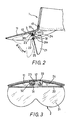
- Figure 1 is a perspective, exploded view of a visor cap constructed in accordance with the present invention;
- Figure 2 is a longitudinal sectional view of the visor cap in the assembled state taken along the line I-I of Figure 1;
- Figure 3 is a transverse sectional view of the visor cap in the assembled state taken along the line II-II of Figure 1; and
- Figure 4 is a bottom view of just the visor of the visor cap.
- The visor cap of the present invention, designated generally by the
numeral 01, comprises a cap body 1 having at least avisor 11, an eye shield 2 and amounting block 3. - The cap body 1 may be of any type having the
visor 11 attached thereto. Thevisor 11 may be integrally formed of a non-opaque plastics material and is to project forwardly of the cap body 1. Formed on the lower side middle portion of thevisor 11 is adovetail groove 12 which is directed longitudinally forwards from the rear edge of thevisor 11 and defines anentry port 121 at its rear. Theattachment groove 12 may alternatively be formed in a separate member affixed to the surface of thevisor 11. - The eye shield 2, such as sun glasses or wind-shield goggles, has a single piece wind-
shield lens 21 and a mountingframe 22 having in its lower end agroove 25 for frictional attachment thereto of the upper end of thelens 21. Themounting frame 22, on its upper side middle portion, is formed integrally with a transversely extendingmounting shaft 23. More particularly, the eye shield 2 includes a pair of upstanding legs whose upper ends are connected by themounting shaft 23, so that the legs and the mounting shaft when considered together are of inverted channel shape. On either side of themounting shaft 23 is formed in a symmetrical manner one of a pair of triangularsupplementary plates 24 to conform upwardly to the curve of the underside surface of thevisor 11. It should be noted that thetransverse mounting shaft 23 may alternatively be formed directly between to connect the pair ofsupplementary plates 24. Furthermore, theaforesaid mounting frame 22 having themounting shaft 23 may alternatively be integrally formed with thelens 21 from a transparent plastics material. - The
mounting block 3 is integrally moulded from a synthetic resin material, such as a resiliently deformable plastics material, of a trapezoidal shape provided at the shorter side end with an opening 31a. The opening 31a leads to a wider retainingchannel 31 and a furthernarrow channel 31b. The opening 31a is substantially narrower in width than themounting shaft 23 which can be snap inserted through the opening 31a into theretaining channel 31 to be pivotally movable therein. Themounting block 3 also includes a pair ofslots 32 extending in planes perpendicular to themounting shaft 23 for receiving respective ones of said legs at the ends of themounting shaft 23. Themounting block 3 may omit theslots 32 if there are no legs or if the legs are to be disposed beyond the ends of themounting block 3. The broader side end of themounting block 3 is so configured that itsbase 33 can be engaged frictionally and moved back and forth in the above saidgroove 12. - In use and operation of the
visor cap 01, when it is desired that the eye shield 2 be mounted on the cap body 1, themounting block 3 is first attached by itsbase 33 to thegroove 12 on the underside surface of thevisor 11 through theentry port 121 located at the rear side of thegroove 12. Following this arrangement, themounting block 3 is now capable of being slid back and forth and of being frictionally retained at any selected position along thegroove 12. The eye shield 2 is next mounted by snapping in position themounting shaft 23 thereof in theretaining channel 31 of themounting block 3, whereby themounting shaft 23 is capable of being frictionally retained at any selected angle within theretaining channel 31 and is prevented by the relatively narrowermouthed opening 31a from easily falling out. - In this arrangement, depending on circumstances a user may desire to turn the
lens 21 of the eye shield 2 downward in a direction as indicated by the arrow A in Figure 2 to be in a substantially vertical position relative to thevisor 11 for use. While in this downward position of thelens 21, the eye shield 2 together with themounting block 3 disposed thereabove may also be moved back and forth in directions as indicated by arrows C and D in Figure 2 to enable the wearer to appropriately adjust the distance between thelens 21 and the face. Angular adjustment of thelens 21 is possible, and to facilitate frictional retention the outer circumference of themounting shaft 23 and the inner wall of theretaining channel 31 may be formed as circumferentially arranged and transversely extending series of interengagable teeth. Again, when not in use, thelens 21 may be raised directly upwardly in direction as indicated by the arrow B in Figure 2, thus permitting thelens 21 to abut against the underside of thevisor 11. - The
lens 21 may be separately disconnected and removed from themounting block 3, or thelens 21 may alternatively be detached out together with themounting block 3 from thevisor 11, so that the cap body 1 can be separately used. - From the foregoing, it is seen that the preferred embodiment of the visor cap in accordance with the present invention provides an eye shield which can be readily attached to the bottom surface of the visor through the intermediary of the mounting block. When mounted in position on the visor, the eye shield lens can either be conveniently and quickly removed or when it is not in use the lens can be raised up to rest closely adjacent the underside of the visor. The design and construction of the mounting block permits ready attachment and detachment of the eye shield to and from the visor, as well as ready attachment and detachment of the two part relative to each other. The frictional engagement of the mounting block with the visor further allows the adjustment of distance to be made between the position of the eye shield and the eyes.
Claims (9)
Priority Applications (5)
| Application Number | Priority Date | Filing Date | Title |
|---|---|---|---|
| US07/132,552 US4819274A (en) | 1987-12-22 | 1987-12-14 | Visor cap with a detachable eye shield |
| AT87311327T ATE81266T1 (en) | 1987-12-22 | 1987-12-22 | CAP WITH PILLOW AND SWINGING EYE PROTECTION VISOR. |
| ES198787311327T ES2035088T3 (en) | 1987-12-22 | 1987-12-22 | CAP WITH VISOR AND PIVOTABLE EYE PROTECTOR. |
| EP87311327A EP0321617B1 (en) | 1987-12-22 | 1987-12-22 | Cap with visor and pivotable eye shield |
| DE8787311327T DE3782170T2 (en) | 1987-12-22 | 1987-12-22 | BEANIE WITH UMBRELLA AND SWIVELING EYE PROTECTOR. |
Applications Claiming Priority (1)
| Application Number | Priority Date | Filing Date | Title |
|---|---|---|---|
| EP87311327A EP0321617B1 (en) | 1987-12-22 | 1987-12-22 | Cap with visor and pivotable eye shield |
Publications (2)
| Publication Number | Publication Date |
|---|---|
| EP0321617A1 true EP0321617A1 (en) | 1989-06-28 |
| EP0321617B1 EP0321617B1 (en) | 1992-10-07 |
Family
ID=8198157
Family Applications (1)
| Application Number | Title | Priority Date | Filing Date |
|---|---|---|---|
| EP87311327A Expired EP0321617B1 (en) | 1987-12-22 | 1987-12-22 | Cap with visor and pivotable eye shield |
Country Status (5)
| Country | Link |
|---|---|
| US (1) | US4819274A (en) |
| EP (1) | EP0321617B1 (en) |
| AT (1) | ATE81266T1 (en) |
| DE (1) | DE3782170T2 (en) |
| ES (1) | ES2035088T3 (en) |
Cited By (9)
| Publication number | Priority date | Publication date | Assignee | Title |
|---|---|---|---|---|
| EP0412737A1 (en) * | 1989-08-07 | 1991-02-13 | Buice, Stephen M. | An improved sun visor with eyeshield and method therefor |
| WO1993022946A1 (en) * | 1992-05-14 | 1993-11-25 | Nicolas Simone | Device for attaching a pair of spectacles to head gear |
| EP0602269A1 (en) * | 1992-12-10 | 1994-06-22 | Sheng-Tong Day | Eye shield assembly for cap visor |
| EP0729715A1 (en) * | 1995-03-02 | 1996-09-04 | Marc-Olivier Huchet | Visored cap with sun-glasses |
| EP0760963A1 (en) * | 1994-05-09 | 1997-03-12 | Robert B. Cahill | Clip-on sunglasses assembly for the brim of a hat |
| GB2337443A (en) * | 1998-05-23 | 1999-11-24 | Ernest Bateman | Spectacles mounted under the brim of a hat |
| EP1020753A1 (en) * | 1999-01-14 | 2000-07-19 | Angelini Design di Lamberto Angelini & C. S.a.s. | Sun visor especially for eyeglasses |
| FR2838612A1 (en) * | 2002-04-18 | 2003-10-24 | Gilbert Birglen | Baseball cap includes a single piece shell with a peak, the shell including a decorative cloth piece made of a film that reflects infrared and ultraviolet radiation and contains an element for absorbing humidity |
| EP1754991A1 (en) * | 2005-08-18 | 2007-02-21 | Yu-Teng Hsiao | Movable magnetic coupling system for securing a one-piece lens to a cap visor |
Families Citing this family (28)
| Publication number | Priority date | Publication date | Assignee | Title |
|---|---|---|---|---|
| DE69006207T2 (en) * | 1990-01-04 | 1994-05-11 | Emerson Electric Co | Chuck for threading machine. |
| US5056164A (en) * | 1990-03-15 | 1991-10-15 | Lisle Tommy W | Visor cap and eye glass organization |
| US5105475A (en) * | 1990-07-20 | 1992-04-21 | Countryside Products Co. | Headgear with eyeglass |
| US5526178A (en) * | 1991-02-22 | 1996-06-11 | Front-Row Products Inc. | Binocular |
| IL97330A0 (en) * | 1991-02-22 | 1992-05-25 | Goldstein Pinchas | Binocular telescope |
| US5129102A (en) * | 1991-07-22 | 1992-07-14 | Solo Alan J | Cap provided with removable flip up and down glasses |
| US5347655A (en) * | 1993-07-09 | 1994-09-20 | I-Sha-Vi, Inc. | Eyewear in combination with a visor |
| US5412812A (en) * | 1993-11-23 | 1995-05-09 | Gatchalian; Bayani V. | Detachable eyeshield attachment for visor caps or the like |
| US5689827A (en) * | 1996-03-13 | 1997-11-25 | Ryder; Curtis J. | Fastener assemblies for combination visor and eyeshield |
| US5615413A (en) * | 1996-03-19 | 1997-04-01 | Bower; Kirk | Eye shield for visor or cap bill |
| US5987640A (en) * | 1998-12-08 | 1999-11-23 | Ryder; Curtis J. | Visor and eyeshield assembly and method |
| US6662371B2 (en) | 2001-03-07 | 2003-12-16 | Jae Hoon Shin | Reconfigurable eyewear apparatus for headwear visor |
| KR20010070758A (en) * | 2001-06-05 | 2001-07-27 | 홍창학 | A cap having sunglasses |
| US6491390B1 (en) | 2001-09-21 | 2002-12-10 | Jack Provost | Clip-on glasses |
| US6595635B2 (en) | 2001-10-12 | 2003-07-22 | Mageyes, Inc. | Apparatus for positioning a magnifying lens |
| US7051406B1 (en) | 2003-01-15 | 2006-05-30 | Russell Earl Morris | Apparatus holder for hats |
| US7178278B1 (en) | 2003-01-15 | 2007-02-20 | Russell Earl Morris | Method for interchangeably promoting a business on a hat |
| US6959989B2 (en) * | 2003-08-18 | 2005-11-01 | Barent Holm | Hard-hat flip-up safety glasses |
| WO2008025083A1 (en) * | 2006-08-31 | 2008-03-06 | David John Springer | Hard hat with attached safety glasses |
| AU2006220433B2 (en) * | 2006-09-21 | 2008-11-13 | Yung-Ming Huang | Cap assembly with eyeglasses |
| KR100861983B1 (en) * | 2007-06-26 | 2008-10-07 | 주식회사 홍진에이치제이씨 | Sunvisor assembly and helmet having same |
| FR2919734A1 (en) * | 2007-08-03 | 2009-02-06 | Hassan Ouerdani | Cap, has integrated glass fixed on cap by fixation system to maintain glass on cap in articulated manner so that glass is movable, removable and orientable for permitting usage of glass with cap or in independent manner |
| US8621663B2 (en) * | 2008-06-11 | 2014-01-07 | Honeywell International Inc. | Eye protectors |
| US9119434B2 (en) * | 2008-06-11 | 2015-09-01 | Morning Pride Manufacturing, LLC. | Eye protectors |
| US8434162B2 (en) * | 2008-06-11 | 2013-05-07 | Morning Pride Manufacturing, L.L.C. | Eye protectors |
| ES1076497Y (en) * | 2012-02-20 | 2012-06-12 | Italo Polifroni | CAP WITH INCORPORATED GLASSES |
| US20190391384A1 (en) * | 2018-06-21 | 2019-12-26 | Valerie Rushmere | Headwear with built-in magnifier |
| TWI670519B (en) * | 2019-01-04 | 2019-09-01 | 廣達電腦股份有限公司 | Wearable display device |
Citations (8)
| Publication number | Priority date | Publication date | Assignee | Title |
|---|---|---|---|---|
| US1485842A (en) * | 1922-08-23 | 1924-03-04 | James J Fisher | Lamp holder for miners' caps |
| US2619641A (en) * | 1951-05-16 | 1952-12-02 | Vaca Humberto | Eyeshield for headgears |
| US2654089A (en) * | 1948-10-09 | 1953-10-06 | Clearasite Corp Of America Inc | Combination cap and eyeshield |
| US2690586A (en) * | 1951-04-26 | 1954-10-05 | United Carr Fastener Corp | Hinge assembly |
| FR1094289A (en) * | 1953-09-11 | 1955-05-16 | Synthetic cap visor | |
| DE1054721B (en) * | 1952-11-24 | 1959-04-09 | Turnwald Gmbh | Protective helmet or the like. |
| US3273163A (en) * | 1964-12-18 | 1966-09-20 | Welsh Mfg Co | Accessory attachment to a hard hat |
| FR2221117A1 (en) * | 1973-03-13 | 1974-10-11 | Persson Anders |
Family Cites Families (3)
| Publication number | Priority date | Publication date | Assignee | Title |
|---|---|---|---|---|
| US2538607A (en) * | 1948-04-19 | 1951-01-16 | Vaca Humberto | Eyeshield for headgear |
| US2725560A (en) * | 1948-07-28 | 1955-12-06 | Felport Inc | Combination cap and eyeshield |
| FR1104655A (en) * | 1954-07-16 | 1955-11-23 | Headgear with visor holder with articulated frame |
-
1987
- 1987-12-14 US US07/132,552 patent/US4819274A/en not_active Expired - Fee Related
- 1987-12-22 DE DE8787311327T patent/DE3782170T2/en not_active Expired - Fee Related
- 1987-12-22 AT AT87311327T patent/ATE81266T1/en not_active IP Right Cessation
- 1987-12-22 EP EP87311327A patent/EP0321617B1/en not_active Expired
- 1987-12-22 ES ES198787311327T patent/ES2035088T3/en not_active Expired - Lifetime
Patent Citations (8)
| Publication number | Priority date | Publication date | Assignee | Title |
|---|---|---|---|---|
| US1485842A (en) * | 1922-08-23 | 1924-03-04 | James J Fisher | Lamp holder for miners' caps |
| US2654089A (en) * | 1948-10-09 | 1953-10-06 | Clearasite Corp Of America Inc | Combination cap and eyeshield |
| US2690586A (en) * | 1951-04-26 | 1954-10-05 | United Carr Fastener Corp | Hinge assembly |
| US2619641A (en) * | 1951-05-16 | 1952-12-02 | Vaca Humberto | Eyeshield for headgears |
| DE1054721B (en) * | 1952-11-24 | 1959-04-09 | Turnwald Gmbh | Protective helmet or the like. |
| FR1094289A (en) * | 1953-09-11 | 1955-05-16 | Synthetic cap visor | |
| US3273163A (en) * | 1964-12-18 | 1966-09-20 | Welsh Mfg Co | Accessory attachment to a hard hat |
| FR2221117A1 (en) * | 1973-03-13 | 1974-10-11 | Persson Anders |
Cited By (12)
| Publication number | Priority date | Publication date | Assignee | Title |
|---|---|---|---|---|
| EP0412737A1 (en) * | 1989-08-07 | 1991-02-13 | Buice, Stephen M. | An improved sun visor with eyeshield and method therefor |
| WO1993022946A1 (en) * | 1992-05-14 | 1993-11-25 | Nicolas Simone | Device for attaching a pair of spectacles to head gear |
| US5720040A (en) * | 1992-05-14 | 1998-02-24 | Simone; Nicolas | Device for attaching a pair of spectacles to headgear |
| EP0602269A1 (en) * | 1992-12-10 | 1994-06-22 | Sheng-Tong Day | Eye shield assembly for cap visor |
| EP0760963A1 (en) * | 1994-05-09 | 1997-03-12 | Robert B. Cahill | Clip-on sunglasses assembly for the brim of a hat |
| EP0760963A4 (en) * | 1994-05-09 | 1997-10-01 | Robert B Cahill | Clip-on sunglasses assembly for the brim of a hat |
| EP0729715A1 (en) * | 1995-03-02 | 1996-09-04 | Marc-Olivier Huchet | Visored cap with sun-glasses |
| FR2731136A1 (en) * | 1995-03-02 | 1996-09-06 | Huchet Marc Olivier | VISOR CAP WITH SUNGLASSES |
| GB2337443A (en) * | 1998-05-23 | 1999-11-24 | Ernest Bateman | Spectacles mounted under the brim of a hat |
| EP1020753A1 (en) * | 1999-01-14 | 2000-07-19 | Angelini Design di Lamberto Angelini & C. S.a.s. | Sun visor especially for eyeglasses |
| FR2838612A1 (en) * | 2002-04-18 | 2003-10-24 | Gilbert Birglen | Baseball cap includes a single piece shell with a peak, the shell including a decorative cloth piece made of a film that reflects infrared and ultraviolet radiation and contains an element for absorbing humidity |
| EP1754991A1 (en) * | 2005-08-18 | 2007-02-21 | Yu-Teng Hsiao | Movable magnetic coupling system for securing a one-piece lens to a cap visor |
Also Published As
| Publication number | Publication date |
|---|---|
| DE3782170D1 (en) | 1992-11-12 |
| EP0321617B1 (en) | 1992-10-07 |
| DE3782170T2 (en) | 1993-04-08 |
| ES2035088T3 (en) | 1993-04-16 |
| US4819274A (en) | 1989-04-11 |
| ATE81266T1 (en) | 1992-10-15 |
Similar Documents
| Publication | Publication Date | Title |
|---|---|---|
| EP0321617B1 (en) | Cap with visor and pivotable eye shield | |
| US5533207A (en) | Positionable sunglasses and cap combination | |
| US5335025A (en) | Detachable mounting for sunshade and sunglasses on vision correcting eyeglasses | |
| US4934807A (en) | Sunglasses having detachable absorber strip | |
| US5319396A (en) | Eyeglasses and goggles | |
| US5261124A (en) | Eye shield assembly for cap visor | |
| US5423092A (en) | Goggles and sunglasses | |
| US5412814A (en) | Protective sports headgear | |
| US5339119A (en) | Eye protection device comprising a foam rubber-like resilient insert member | |
| US5410763A (en) | Eyeshield with detachable components | |
| US7703153B2 (en) | Combination hat and sunglasses/goggles | |
| US4951316A (en) | Sun visor with eyeshield and method therefor | |
| AU594083B2 (en) | Spectacles, visors and the like | |
| US4955087A (en) | Combined visor and sunglasses assembly | |
| CA2073646A1 (en) | Cap provided with removable flip up and down glasses | |
| WO1991013380A1 (en) | Combination prescription lens and sunglasses assembly | |
| AU2463802A (en) | Face shield and face shield support assembly | |
| US3804495A (en) | Rear vision reflection device for a helmet | |
| US5438378A (en) | Visor for eyeglasses | |
| AU685633B2 (en) | Clip-on sunglasses assembly for the brim of a hat | |
| AU2006225274A1 (en) | A Set of Eyeglasses with Attachment System | |
| US3837005A (en) | Device for the protection of the eyes and face | |
| US4925290A (en) | Adjustable spectacle frame | |
| CA1295091C (en) | Visor cap with a detachable eye shield | |
| USD303040S (en) | Protective visor for use when bathing |
Legal Events
| Date | Code | Title | Description |
|---|---|---|---|
| PUAI | Public reference made under article 153(3) epc to a published international application that has entered the european phase |
Free format text: ORIGINAL CODE: 0009012 |
|
| 17P | Request for examination filed |
Effective date: 19880114 |
|
| AK | Designated contracting states |
Kind code of ref document: A1 Designated state(s): AT BE CH DE ES FR GB IT LI LU NL SE |
|
| 17Q | First examination report despatched |
Effective date: 19910614 |
|
| GRAA | (expected) grant |
Free format text: ORIGINAL CODE: 0009210 |
|
| AK | Designated contracting states |
Kind code of ref document: B1 Designated state(s): AT BE CH DE ES FR GB IT LI LU NL SE |
|
| REF | Corresponds to: |
Ref document number: 81266 Country of ref document: AT Date of ref document: 19921015 Kind code of ref document: T |
|
| REF | Corresponds to: |
Ref document number: 3782170 Country of ref document: DE Date of ref document: 19921112 |
|
| ITF | It: translation for a ep patent filed |
Owner name: JACOBACCI CASETTA & PERANI S.P.A. |
|
| ET | Fr: translation filed | ||
| REG | Reference to a national code |
Ref country code: ES Ref legal event code: FG2A Ref document number: 2035088 Country of ref document: ES Kind code of ref document: T3 |
|
| PLBE | No opposition filed within time limit |
Free format text: ORIGINAL CODE: 0009261 |
|
| STAA | Information on the status of an ep patent application or granted ep patent |
Free format text: STATUS: NO OPPOSITION FILED WITHIN TIME LIMIT |
|
| 26N | No opposition filed | ||
| PGFP | Annual fee paid to national office [announced via postgrant information from national office to epo] |
Ref country code: FR Payment date: 19931209 Year of fee payment: 7 |
|
| PGFP | Annual fee paid to national office [announced via postgrant information from national office to epo] |
Ref country code: GB Payment date: 19931214 Year of fee payment: 7 Ref country code: AT Payment date: 19931214 Year of fee payment: 7 |
|
| PGFP | Annual fee paid to national office [announced via postgrant information from national office to epo] |
Ref country code: SE Payment date: 19931215 Year of fee payment: 7 |
|
| PGFP | Annual fee paid to national office [announced via postgrant information from national office to epo] |
Ref country code: ES Payment date: 19931222 Year of fee payment: 7 |
|
| PGFP | Annual fee paid to national office [announced via postgrant information from national office to epo] |
Ref country code: CH Payment date: 19931223 Year of fee payment: 7 |
|
| PGFP | Annual fee paid to national office [announced via postgrant information from national office to epo] |
Ref country code: DE Payment date: 19931227 Year of fee payment: 7 |
|
| PGFP | Annual fee paid to national office [announced via postgrant information from national office to epo] |
Ref country code: NL Payment date: 19931231 Year of fee payment: 7 |
|
| PGFP | Annual fee paid to national office [announced via postgrant information from national office to epo] |
Ref country code: LU Payment date: 19940131 Year of fee payment: 7 Ref country code: BE Payment date: 19940131 Year of fee payment: 7 |
|
| EPTA | Lu: last paid annual fee | ||
| PG25 | Lapsed in a contracting state [announced via postgrant information from national office to epo] |
Ref country code: LU Free format text: LAPSE BECAUSE OF NON-PAYMENT OF DUE FEES Effective date: 19941222 Ref country code: GB Effective date: 19941222 Ref country code: AT Effective date: 19941222 |
|
| PG25 | Lapsed in a contracting state [announced via postgrant information from national office to epo] |
Ref country code: SE Effective date: 19941223 Ref country code: ES Free format text: LAPSE BECAUSE OF EXPIRATION OF PROTECTION Effective date: 19941223 |
|
| PG25 | Lapsed in a contracting state [announced via postgrant information from national office to epo] |
Ref country code: LI Effective date: 19941231 Ref country code: CH Effective date: 19941231 Ref country code: BE Effective date: 19941231 |
|
| EAL | Se: european patent in force in sweden |
Ref document number: 87311327.8 |
|
| BERE | Be: lapsed |
Owner name: DAY SHENG-TONG Effective date: 19941231 |
|
| PG25 | Lapsed in a contracting state [announced via postgrant information from national office to epo] |
Ref country code: NL Effective date: 19950701 |
|
| GBPC | Gb: european patent ceased through non-payment of renewal fee |
Effective date: 19941222 |
|
| PG25 | Lapsed in a contracting state [announced via postgrant information from national office to epo] |
Ref country code: FR Effective date: 19950831 |
|
| REG | Reference to a national code |
Ref country code: CH Ref legal event code: PL |
|
| NLV4 | Nl: lapsed or anulled due to non-payment of the annual fee |
Effective date: 19950701 |
|
| PG25 | Lapsed in a contracting state [announced via postgrant information from national office to epo] |
Ref country code: DE Effective date: 19950901 |
|
| EUG | Se: european patent has lapsed |
Ref document number: 87311327.8 |
|
| REG | Reference to a national code |
Ref country code: FR Ref legal event code: ST |
|
| REG | Reference to a national code |
Ref country code: ES Ref legal event code: FD2A Effective date: 20010301 |
|
| PG25 | Lapsed in a contracting state [announced via postgrant information from national office to epo] |
Ref country code: IT Free format text: LAPSE BECAUSE OF NON-PAYMENT OF DUE FEES;WARNING: LAPSES OF ITALIAN PATENTS WITH EFFECTIVE DATE BEFORE 2007 MAY HAVE OCCURRED AT ANY TIME BEFORE 2007. THE CORRECT EFFECTIVE DATE MAY BE DIFFERENT FROM THE ONE RECORDED. Effective date: 20051222 |