EP0321414A2 - Spritze mit selbsttätiger Sicherung - Google Patents
Spritze mit selbsttätiger Sicherung Download PDFInfo
- Publication number
- EP0321414A2 EP0321414A2 EP88810868A EP88810868A EP0321414A2 EP 0321414 A2 EP0321414 A2 EP 0321414A2 EP 88810868 A EP88810868 A EP 88810868A EP 88810868 A EP88810868 A EP 88810868A EP 0321414 A2 EP0321414 A2 EP 0321414A2
- Authority
- EP
- European Patent Office
- Prior art keywords
- syringe
- piston
- syringe according
- piston rod
- rod
- Prior art date
- Legal status (The legal status is an assumption and is not a legal conclusion. Google has not performed a legal analysis and makes no representation as to the accuracy of the status listed.)
- Granted
Links
Images


Classifications
-
- A—HUMAN NECESSITIES
- A61—MEDICAL OR VETERINARY SCIENCE; HYGIENE
- A61M—DEVICES FOR INTRODUCING MEDIA INTO, OR ONTO, THE BODY; DEVICES FOR TRANSDUCING BODY MEDIA OR FOR TAKING MEDIA FROM THE BODY; DEVICES FOR PRODUCING OR ENDING SLEEP OR STUPOR
- A61M5/00—Devices for bringing media into the body in a subcutaneous, intra-vascular or intramuscular way; Accessories therefor, e.g. filling or cleaning devices, arm-rests
- A61M5/50—Devices for bringing media into the body in a subcutaneous, intra-vascular or intramuscular way; Accessories therefor, e.g. filling or cleaning devices, arm-rests having means for preventing re-use, or for indicating if defective, used, tampered with or unsterile
- A61M5/508—Means for preventing re-use by disrupting the piston seal, e.g. by puncturing
-
- A—HUMAN NECESSITIES
- A61—MEDICAL OR VETERINARY SCIENCE; HYGIENE
- A61M—DEVICES FOR INTRODUCING MEDIA INTO, OR ONTO, THE BODY; DEVICES FOR TRANSDUCING BODY MEDIA OR FOR TAKING MEDIA FROM THE BODY; DEVICES FOR PRODUCING OR ENDING SLEEP OR STUPOR
- A61M5/00—Devices for bringing media into the body in a subcutaneous, intra-vascular or intramuscular way; Accessories therefor, e.g. filling or cleaning devices, arm-rests
- A61M5/178—Syringes
- A61M5/31—Details
- A61M5/32—Needles; Details of needles pertaining to their connection with syringe or hub; Accessories for bringing the needle into, or holding the needle on, the body; Devices for protection of needles
- A61M5/3205—Apparatus for removing or disposing of used needles or syringes, e.g. containers; Means for protection against accidental injuries from used needles
- A61M5/321—Means for protection against accidental injuries by used needles
- A61M5/3213—Caps placed axially onto the needle, e.g. equipped with finger protection guards
-
- A—HUMAN NECESSITIES
- A61—MEDICAL OR VETERINARY SCIENCE; HYGIENE
- A61M—DEVICES FOR INTRODUCING MEDIA INTO, OR ONTO, THE BODY; DEVICES FOR TRANSDUCING BODY MEDIA OR FOR TAKING MEDIA FROM THE BODY; DEVICES FOR PRODUCING OR ENDING SLEEP OR STUPOR
- A61M5/00—Devices for bringing media into the body in a subcutaneous, intra-vascular or intramuscular way; Accessories therefor, e.g. filling or cleaning devices, arm-rests
- A61M5/50—Devices for bringing media into the body in a subcutaneous, intra-vascular or intramuscular way; Accessories therefor, e.g. filling or cleaning devices, arm-rests having means for preventing re-use, or for indicating if defective, used, tampered with or unsterile
- A61M5/5066—Means for preventing re-use by disconnection of piston and piston-rod
-
- A—HUMAN NECESSITIES
- A61—MEDICAL OR VETERINARY SCIENCE; HYGIENE
- A61M—DEVICES FOR INTRODUCING MEDIA INTO, OR ONTO, THE BODY; DEVICES FOR TRANSDUCING BODY MEDIA OR FOR TAKING MEDIA FROM THE BODY; DEVICES FOR PRODUCING OR ENDING SLEEP OR STUPOR
- A61M5/00—Devices for bringing media into the body in a subcutaneous, intra-vascular or intramuscular way; Accessories therefor, e.g. filling or cleaning devices, arm-rests
- A61M5/178—Syringes
- A61M5/31—Details
- A61M2005/3117—Means preventing contamination of the medicament compartment of a syringe
- A61M2005/3121—Means preventing contamination of the medicament compartment of a syringe via the proximal end of a syringe, i.e. syringe end opposite to needle cannula mounting end
Definitions
- the subject of the present invention is a self-protecting and non-reusable syringe which can be either pre-filled or filled just before use, for general-purpose use, comprising a piston intended to deliver a solution which is in the body of the syringe under the action of 'a rod for the injection of this solution in a patient, an animal or in any other agent or medium, the lower part of said syringe body being extended by a needle protected by a cap.
- the present invention proposes the production of a syringe of simple and rational design, with guarantees intervening in stages, i.e. successively when one of them dies must, for example as a result of intentional manipulation intended to make the syringe reusable.
- This objective is achieved by means of a syringe corresponding to the preamble of claim 1, characterized in that the piston is arranged and shaped so as to only move under the action of the piston rod in the direction of the push. , i.e. of the discharge of the solution through the needle, to allow only a suction limited to a "vein test", and to exclude any other maneuver, so that the syringe becomes completely inoperative after the first use.
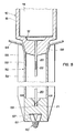
- FIG. 1 shows the general structure of the syringe according to the invention. It consists of a cylindrical syringe body 10, the lower end of which ends with a nozzle in which is fixed, or at the end of which is a needle 20, a piston, a piston rod 50, a flange 70, and a closure membrane 80.
- the syringe itself is presented either pre-filled by the distributor (producer, manufacturer, packaging laboratory for active ingredients, etc.), therefore directly ready for use, or empty, in which case it will be filled according to an exposed process later, when an injection is planned.
- the distributor producer, manufacturer, packaging laboratory for active ingredients, etc.
- empty in which case it will be filled according to an exposed process later, when an injection is planned.
- the "pre-filled” presentation it is important, on the one hand, that the syringe body, respectively the walls of the syringe body, be made of a perfectly impermeable material (vitrified plastic for example), and that , on the other hand, the needle is constituted so that all the conditions on the anti-corrosion plan are respected.
- the central part 73 in the form of a tube of the flange 70 whose upper face 71, not shown in plan, can be circular, or, preferably, in the form of a rhombus flattened at angles rounded, the wings 72 located on the long diagonal of the rhombus, facilitating the "grip" of the syringe during its implementation.
- the embedding of the central part 73 is obtained according to a usual method not described; it extends over an adequate distance about a cm, said part 73 playing at the same time the roles of guide to the piston rod 50 and subsidiary safety.
- the upper opening of the syringe, whatever its mode of presentation, is hermetically closed by the closing membrane 80 disposed on the face 71 of the collar 70, in order to preserve sterilization well.
- Said membrane will be easily detached from the collar by simultaneously lifting and pulling the ear 81 which protrudes from the latter.
- any other means such as cover, cap, or plug, plugging in or fitting into the opening of the collar, may be used to achieve this closure.
- the piston preferably made up, according to the example described, of three elements, namely a piston body 30, a central lug 60 and an annular seal 40 A partial section of this piston, on a large scale, is shown in fig. 2.
- the piston body 30, made of plastic or any other material, has approximately the shape of a mushroom, whose axis of revolution is superimposed on the axis of the syringe body.
- the diameter of the cap 31 does not have to correspond exactly to the internal diameter of the syringe body 10; on the contrary, it will preferably be chosen slightly less than the latter, but greater than the diameter of the central part 73 of the flange 70.
- the height of the cap 31, for its part, may be chosen less than the diameter of the syringe body, since any risk of tilting of the piston body 30 is eliminated, thanks to the guidance of the piston rod 50 mentioned above.
- the lower part of the foot 32 ends in a slight rim 33; the upper face 34 of said flange will advantageously have a generally rounded or frustoconical shape, the top of which is located towards the top of the syringe body.
- This rim in a variant, can nevertheless be removed so that the foot 32 is then in the form of a straight cylinder.
- the piston body 30 finally comprises an orifice or a central opening 35.
- this is frustoconical, in part 31, ie. upper, the top of the cone being located on the side of the nozzle 12.
- this frustoconical part has a thread 37 with a large pitch on the right or on the left.
- the lower part of the opening is cylindrical and smooth. It extends the mentioned truncated cone.
- the central recess 35 will of course be closed beforehand at its lower part by means of a sealing membrane 39 applied to the lower face 38 of the foot 32.
- the opening 35 allows, when the syringe is previously empty (presentation "to be filled"), to introduce the injection solution (s) from above into the syringe body, by gravitation or any other means, when the use is imminent, and is intended to receive the lug 60 which is presented as a massive or partially massive piece, having an axis of symmetry superimposed on that of the syringe body.
- this lug is shown in phantom in place on the opening 35.
- the upper part 62 of this lug is plugged in or slipped beforehand into a housing 51 of the piston rod 50, said housing having the shape of a dovetail as seen in FIG. 3A.
- This upper part made of flexible material and split in its middle forms two lips 64 in the form of an opening V 63.
- the sides 57 of the housing 51 in dovetail retain these lips and consequently the lug 60.
- the lower part 61 is frustoconical and has a thread with a large pitch corresponding to the internal thread 37 of the piston body.
- the top of the truncated cone (small base 66) preferably ends with a spherical cap. The lug can be screwed into the piston body until the bearing face 65 comes into contact with the upper face of said piston body.
- Fig. 3B shows another arrangement for retaining the lug in a housing 51 ′.
- the housing 51 ′ being parallelepipedal, the lips 64 of the lug 60 exert a bearing force on the sides 57 ′; the opening 63 of the V, in this case, is almost closed.
- annular seal 40 (fig. 1 and 2) is placed on the foot 32, respectively in the groove 36 formed by the lower face of the cap 31 and the upper face 34 of the flange 33.
- the piston rod 50 On the nozzle 12 which extends from the underside of the syringe body is arranged the piston rod 50, which, in this place, surrounds the needle 20.
- This arrangement, as well as preferred embodiments of this rod will be described using fig. 4A, 4B and 5.
- the piston rod 50 is, in its general form, like a tube which, it should be remembered, is guided by the part 73 of the flange during the injection operation. It should be emphasized that, whatever the section of the tube (cylindrical or polygonal), the inside diameter (or diameter of the circle inscribed when it is a polygon) of said tube is therefore not significantly less than the inside diameter of part 73 of the collar.
- the internal diameter of the tube will be a large multiple - of value 8 for example - of that of the needle 20 housed in the hollow part 52.
- the walls of the tube bear the reference 53.
- this tubular rod 50 fills it in addition to its piston operating function the roles of protective cap of the needle 20 and that of a safety device, before and after use of the syringe, which constitutes another characteristic which is immediately appreciated.
- a plunger rod / protective cap is not necessarily limited to non-reusable syringes, but can extend to all types of syringe.
- Fig. 4A is a cross section of the piston rod showing an embodiment of the section thereof; fig. 4B shows another variant of conformation of this section.
- Other cross-sectional shapes of the piston rod (tube) can of course be provided. But whatever the choice of this section, it must be registered in a circle 56 whose diameter is just less than the inside diameter of the central part 73 of the flange 70.
- the tube has six ribs 56, it being understood that the number of ribs can be chosen differently; in the example of fig. 4B, the section is hexagonal. In both cases the outer edges of the ribs respectively of the edges of the hexagon are inscribed in the circumscribed circle 56, in accordance with the condition described above.
- Fig. 5 shows in section, on the one hand, the upper part of the piston rod arranged on the nozzle 12, and, on the other hand, the lower part according to a preferred embodiment.
- the upper part of the rod 50 opens into a funnel 58, the nozzle being of corresponding shape, i.e. frustoconical, the apex of the cone being situated towards the end 21 of the needle 20.
- These two conical parts are provided with a thread, respectively with a thread with large pitch, so that the rod can easily, so safe, reliable and fast, be attached to the nozzle, especially after use.
- the needle is fixed integrally in the nozzle according to a known process and not described.
- the upper part of the rod ends in a circular ring 54 for supporting the thumb of the hand during the injection, this ring preferably being slightly curved or having a slight slope towards the center.
- the corresponding parts can be smooth cylindrical (fig. 1) or with thread, frustoconical and smooth, of polygonal section, etc.
- the part lower as has already been said during the description relating to the lug 60, comprises a housing 51 whose sides 57 hold said lug by its upper part 62.
- the bottom of the tube of the piston rod has another original feature, namely a housing 59 formed in the axis of the needle 20 and into which is just introduced the end 21 of said needle.
- a housing 59 formed in the axis of the needle 20 and into which is just introduced the end 21 of said needle.
- the housing 59 opens approximately in the form of a guide cone, the diameter of the base circle being chosen to be large enough, so as to facilitate as much as possible the introduction of the end of the needle in said housing.
- the length of the hollow part 52 of the rod 50 is in this case adapted to the length of the needle, so that the "styling" can be properly ensured and that the end 21 of the needle 20 do not come up against the bottom of the housing 59.
- the piston rod 50 comprising at its end the lug 60, is released from the nozzle 12, then brought to the piston body by the top of the syringe body, the membrane 81 having previously been removed.
- the lower part 61 of the lug is engaged in the central recess 35 of the piston body at the same time as a slight rotational movement is carried out, i.e. screwing, so as to secure the rod and the piston.
- This movement of engagement then of rotation is greatly facilitated by the conical shape of the parts 61 (1st operation).
- a "vein test” (3rd operation) is performed before any injection.
- the purpose of this "viene test” is to determine whether the needle, taking into account the type of puncture, is positioned correctly or not. For that, a minimal aspiration makes it possible to note the presence or the absence of blood in the needle.
- a slack Minimal shrinkage is exerted on the piston rod, without this movement, however, causing a rectilinear displacement, strictly speaking, of the entire piston.
- Figs. 7 and 8 show the post-injection situations.
- the piston rod / piston assembly 50, 30, 40, 60 is located at the bottom of the syringe body. It is noted, in this context, that the shape of the bottom of the syringe body matches that of the lower zone of the piston, i.e. of seal and the lower part of the foot of the piston body, which allows optimal evacuation of the solution to be injected. A withdrawal movement is then exerted, i.e. suction on the piston rod, in the direction of the arrow shown in fig. 7 (5th operation).
- the lower half-part 61 of the lug 60 remains screwed into the recess 35 of the piston body 30, while the upper half-part 62 of the lug detaches from the housing 51, this immediately after there has been a first folding of the annular seal 40.
- the seal 40 is supported, on the one hand on the lower face of the cap 31 and the upper face 34 of the flange 33 of the piston body 30, and, on the other hand, laterally on the walls 15 of the syringe body 10 and on the foot 32 of the piston body 30 (sealing).
- the dimensions, the general geometry, and the elasticity of the materials for the upper part 62 of the lug 60 and of the seal 40 are determined by the requirement that, during the suction movement, i.e.
- the diameter of the cavity 52 (tube / piston rod) is chosen to be large enough, so that the needle can be introduced into said cavity with the greatest ease, and therefore without there there is a risk of inadvertent pricking during this "recoiffage" of the needle.
- the piston rod 50 again fulfills its role of needle protective cap and post-employment safety. In fig. 8, it is assumed that the bearing of the first safety device was intentionally bypassed, for the purpose of an attempt at subsequent reuse, by having made the head of the piston rod (50) completely integral with the lug 60 and the piston body 30 by any means.
- the fields of application of the syringe described are very varied, let us cite by way of example the medical, veterinary, research and industrial fields.
- the syringe according to the invention can be manufactured in all sizes and provides a decisive solution to the problems set out in the introduction. Functional and practical, it achieves the desired objectives with real reliability, and also allows manufacturing at the lowest costs.
Landscapes
- Health & Medical Sciences (AREA)
- Engineering & Computer Science (AREA)
- Heart & Thoracic Surgery (AREA)
- Vascular Medicine (AREA)
- Anesthesiology (AREA)
- Biomedical Technology (AREA)
- Hematology (AREA)
- Life Sciences & Earth Sciences (AREA)
- Animal Behavior & Ethology (AREA)
- General Health & Medical Sciences (AREA)
- Public Health (AREA)
- Veterinary Medicine (AREA)
- Environmental & Geological Engineering (AREA)
- Infusion, Injection, And Reservoir Apparatuses (AREA)
Priority Applications (1)
| Application Number | Priority Date | Filing Date | Title |
|---|---|---|---|
| AT88810868T ATE80315T1 (de) | 1987-12-16 | 1988-12-16 | Spritze mit selbsttaetiger sicherung. |
Applications Claiming Priority (2)
| Application Number | Priority Date | Filing Date | Title |
|---|---|---|---|
| CH4906/87 | 1987-12-16 | ||
| CH490687 | 1987-12-16 |
Publications (3)
| Publication Number | Publication Date |
|---|---|
| EP0321414A2 true EP0321414A2 (de) | 1989-06-21 |
| EP0321414A3 EP0321414A3 (en) | 1989-09-20 |
| EP0321414B1 EP0321414B1 (de) | 1992-09-09 |
Family
ID=4284603
Family Applications (1)
| Application Number | Title | Priority Date | Filing Date |
|---|---|---|---|
| EP88810868A Expired - Lifetime EP0321414B1 (de) | 1987-12-16 | 1988-12-16 | Spritze mit selbsttätiger Sicherung |
Country Status (3)
| Country | Link |
|---|---|
| EP (1) | EP0321414B1 (de) |
| AT (1) | ATE80315T1 (de) |
| DE (1) | DE3874504T2 (de) |
Cited By (4)
| Publication number | Priority date | Publication date | Assignee | Title |
|---|---|---|---|---|
| US4973308A (en) * | 1987-05-22 | 1990-11-27 | Ramon M. Rovira | Injection syringe with mechanism preventing reuse |
| US5034002A (en) * | 1989-07-03 | 1991-07-23 | Fabersanitas S.A. | Auto-non-reusable syringe-needle system for injections for a unique use |
| US5078686A (en) * | 1988-06-28 | 1992-01-07 | Bates William T D | Single-use syringe |
| EP1459775A4 (de) * | 2001-12-28 | 2007-08-01 | Terumo Corp | Spritze |
Family Cites Families (3)
| Publication number | Priority date | Publication date | Assignee | Title |
|---|---|---|---|---|
| US1948982A (en) * | 1932-08-15 | 1934-02-27 | Cutter Lab | Hypodermic syringe |
| FR2348708A1 (fr) * | 1976-04-23 | 1977-11-18 | Becton Dickinson France | Ampoule-seringue et son procede d'utilisation |
| CH620126A5 (de) * | 1978-03-10 | 1980-11-14 | Tulcea Sa |
-
1988
- 1988-12-16 EP EP88810868A patent/EP0321414B1/de not_active Expired - Lifetime
- 1988-12-16 DE DE8888810868T patent/DE3874504T2/de not_active Expired - Fee Related
- 1988-12-16 AT AT88810868T patent/ATE80315T1/de not_active IP Right Cessation
Cited By (4)
| Publication number | Priority date | Publication date | Assignee | Title |
|---|---|---|---|---|
| US4973308A (en) * | 1987-05-22 | 1990-11-27 | Ramon M. Rovira | Injection syringe with mechanism preventing reuse |
| US5078686A (en) * | 1988-06-28 | 1992-01-07 | Bates William T D | Single-use syringe |
| US5034002A (en) * | 1989-07-03 | 1991-07-23 | Fabersanitas S.A. | Auto-non-reusable syringe-needle system for injections for a unique use |
| EP1459775A4 (de) * | 2001-12-28 | 2007-08-01 | Terumo Corp | Spritze |
Also Published As
| Publication number | Publication date |
|---|---|
| DE3874504T2 (de) | 1993-04-01 |
| DE3874504D1 (de) | 1992-10-15 |
| EP0321414A3 (en) | 1989-09-20 |
| EP0321414B1 (de) | 1992-09-09 |
| ATE80315T1 (de) | 1992-09-15 |
Similar Documents
| Publication | Publication Date | Title |
|---|---|---|
| CA1247962A (fr) | Ampoule-seringue | |
| EP0336855B1 (de) | Spritze zum einmaligen Gebrauch | |
| CH620126A5 (de) | ||
| EP0393166B1 (de) | Spritze mit injektionsnadel für einmalgebrauch, insbesondere für zahnärztliche zwecke | |
| EP1663102B1 (de) | Vorrichtung zur oralen verabreichung eines medikaments | |
| EP1973592B1 (de) | Vorgefüllte hypodermische spritze mit einer verschlussvorrichtung | |
| EP0693949B1 (de) | Injektionsmodul für eine spritze | |
| EP2863968B1 (de) | Einspritzanordnung | |
| EP1628695A1 (de) | Vorgefüllte spritze mit sicherheitskappe | |
| CH674621A5 (de) | ||
| FR2539302A1 (fr) | Seringue a usage medical | |
| EP3484554B1 (de) | Medizinische vorrichtung mit einem gehäuse und einer vorgefüllten, in dem gehäuse angeordneten spritze | |
| FR2799376A1 (fr) | Dispositif d'injection a usage unique | |
| FR2466253A1 (fr) | Fourreau d'aiguille de seringue, ensemble a seringue a aiguille et son procede d'assemblage | |
| WO1989000432A2 (fr) | Seringue de haute securite non reutilisable | |
| WO2019115974A1 (fr) | Dispositif d'injection cryorésistant prêt à l'emploi | |
| EP0986411B1 (de) | Perfektionierte injektionsspritze mit ansaugvorrichtung | |
| EP0321414B1 (de) | Spritze mit selbsttätiger Sicherung | |
| FR2953416A3 (fr) | Canule et dispositif a canule pour la mise en place d'un implant | |
| FR2644349A1 (fr) | Seringue a utilisation unique | |
| FR2967355A1 (fr) | Seringue dentaire securisee | |
| EP2226089B1 (de) | Sicherheitsspritze | |
| WO1998023315A1 (fr) | Ensemble de manipulation d'une aiguille de seringue hypodermique | |
| FR2643819A1 (fr) | Seringue a usage unique | |
| EP3866888A1 (de) | Passive injektionsvorrichtung mit automatischen sicherungsmitteln |
Legal Events
| Date | Code | Title | Description |
|---|---|---|---|
| PUAI | Public reference made under article 153(3) epc to a published international application that has entered the european phase |
Free format text: ORIGINAL CODE: 0009012 |
|
| AK | Designated contracting states |
Kind code of ref document: A2 Designated state(s): AT BE CH DE ES FR GB GR IT LI LU NL SE |
|
| PUAL | Search report despatched |
Free format text: ORIGINAL CODE: 0009013 |
|
| AK | Designated contracting states |
Kind code of ref document: A3 Designated state(s): AT BE CH DE ES FR GB GR IT LI LU NL SE |
|
| 17P | Request for examination filed |
Effective date: 19900212 |
|
| 17Q | First examination report despatched |
Effective date: 19900330 |
|
| GRAA | (expected) grant |
Free format text: ORIGINAL CODE: 0009210 |
|
| AK | Designated contracting states |
Kind code of ref document: B1 Designated state(s): AT BE CH DE ES FR GB GR IT LI LU NL SE |
|
| PG25 | Lapsed in a contracting state [announced via postgrant information from national office to epo] |
Ref country code: IT Free format text: LAPSE BECAUSE OF FAILURE TO SUBMIT A TRANSLATION OF THE DESCRIPTION OR TO PAY THE FEE WITHIN THE PRE;WARNING: LAPSES OF ITALIAN PATENTS WITH EFFECTIVE DATE BEFORE 2007 MAY HAVE OCCURRED AT ANY TIME BEFORE 2007. THE CORRECT EFFECTIVE DATE MAY BE DIFFERENT FROM THE ONE RECORDED.SCRIBED TIME-LIMIT Effective date: 19920909 Ref country code: SE Effective date: 19920909 Ref country code: ES Free format text: THE PATENT HAS BEEN ANNULLED BY A DECISION OF A NATIONAL AUTHORITY Effective date: 19920909 Ref country code: NL Effective date: 19920909 Ref country code: GR Free format text: LAPSE BECAUSE OF FAILURE TO SUBMIT A TRANSLATION OF THE DESCRIPTION OR TO PAY THE FEE WITHIN THE PRESCRIBED TIME-LIMIT Effective date: 19920909 Ref country code: AT Effective date: 19920909 |
|
| REF | Corresponds to: |
Ref document number: 80315 Country of ref document: AT Date of ref document: 19920915 Kind code of ref document: T |
|
| REF | Corresponds to: |
Ref document number: 3874504 Country of ref document: DE Date of ref document: 19921015 |
|
| PG25 | Lapsed in a contracting state [announced via postgrant information from national office to epo] |
Ref country code: BE Effective date: 19921231 Ref country code: LU Free format text: LAPSE BECAUSE OF NON-PAYMENT OF DUE FEES Effective date: 19921231 |
|
| NLV1 | Nl: lapsed or annulled due to failure to fulfill the requirements of art. 29p and 29m of the patents act | ||
| GBT | Gb: translation of ep patent filed (gb section 77(6)(a)/1977) |
Effective date: 19930217 |
|
| BERE | Be: lapsed |
Owner name: CHANSON ALBERT Effective date: 19921231 |
|
| PLBE | No opposition filed within time limit |
Free format text: ORIGINAL CODE: 0009261 |
|
| STAA | Information on the status of an ep patent application or granted ep patent |
Free format text: STATUS: NO OPPOSITION FILED WITHIN TIME LIMIT |
|
| 26N | No opposition filed | ||
| PGFP | Annual fee paid to national office [announced via postgrant information from national office to epo] |
Ref country code: DE Payment date: 19951229 Year of fee payment: 8 |
|
| PGFP | Annual fee paid to national office [announced via postgrant information from national office to epo] |
Ref country code: CH Payment date: 19960104 Year of fee payment: 8 |
|
| PGFP | Annual fee paid to national office [announced via postgrant information from national office to epo] |
Ref country code: FR Payment date: 19960109 Year of fee payment: 8 Ref country code: GB Payment date: 19960109 Year of fee payment: 8 |
|
| PG25 | Lapsed in a contracting state [announced via postgrant information from national office to epo] |
Ref country code: GB Effective date: 19961216 |
|
| PG25 | Lapsed in a contracting state [announced via postgrant information from national office to epo] |
Ref country code: CH Effective date: 19961231 Ref country code: DE Free format text: LAPSE BECAUSE OF NON-PAYMENT OF DUE FEES Effective date: 19961231 Ref country code: LI Effective date: 19961231 |
|
| GBPC | Gb: european patent ceased through non-payment of renewal fee |
Effective date: 19961216 |
|
| REG | Reference to a national code |
Ref country code: CH Ref legal event code: PL |
|
| PG25 | Lapsed in a contracting state [announced via postgrant information from national office to epo] |
Ref country code: FR Effective date: 19970829 |
|
| REG | Reference to a national code |
Ref country code: FR Ref legal event code: ST |