EP0321365B1 - Dekantierzentrifuge mit einziehbarer Zuführvorrichtung - Google Patents
Dekantierzentrifuge mit einziehbarer Zuführvorrichtung Download PDFInfo
- Publication number
- EP0321365B1 EP0321365B1 EP88420415A EP88420415A EP0321365B1 EP 0321365 B1 EP0321365 B1 EP 0321365B1 EP 88420415 A EP88420415 A EP 88420415A EP 88420415 A EP88420415 A EP 88420415A EP 0321365 B1 EP0321365 B1 EP 0321365B1
- Authority
- EP
- European Patent Office
- Prior art keywords
- spout
- plug
- immovable
- integral
- bowl
- Prior art date
- Legal status (The legal status is an assumption and is not a legal conclusion. Google has not performed a legal analysis and makes no representation as to the accuracy of the status listed.)
- Expired - Lifetime
Links
- 239000007788 liquid Substances 0.000 claims description 11
- 238000000605 extraction Methods 0.000 claims description 5
- 230000001681 protective effect Effects 0.000 claims description 5
- 238000006073 displacement reaction Methods 0.000 claims description 3
- 238000011144 upstream manufacturing Methods 0.000 claims description 3
- 239000012857 radioactive material Substances 0.000 claims description 2
- 238000012958 reprocessing Methods 0.000 claims description 2
- 238000007599 discharging Methods 0.000 claims 1
- 230000000694 effects Effects 0.000 description 4
- 239000002184 metal Substances 0.000 description 2
- 230000007797 corrosion Effects 0.000 description 1
- 238000005260 corrosion Methods 0.000 description 1
- 230000002452 interceptive effect Effects 0.000 description 1
- 238000012423 maintenance Methods 0.000 description 1
- 238000004519 manufacturing process Methods 0.000 description 1
- 238000000034 method Methods 0.000 description 1
- 238000012545 processing Methods 0.000 description 1
- 230000005855 radiation Effects 0.000 description 1
- 230000002285 radioactive effect Effects 0.000 description 1
- 230000035939 shock Effects 0.000 description 1
Images
Classifications
-
- B—PERFORMING OPERATIONS; TRANSPORTING
- B04—CENTRIFUGAL APPARATUS OR MACHINES FOR CARRYING-OUT PHYSICAL OR CHEMICAL PROCESSES
- B04B—CENTRIFUGES
- B04B1/00—Centrifuges with rotary bowls provided with solid jackets for separating predominantly liquid mixtures with or without solid particles
-
- B—PERFORMING OPERATIONS; TRANSPORTING
- B04—CENTRIFUGAL APPARATUS OR MACHINES FOR CARRYING-OUT PHYSICAL OR CHEMICAL PROCESSES
- B04B—CENTRIFUGES
- B04B11/00—Feeding, charging, or discharging bowls
- B04B11/04—Periodical feeding or discharging; Control arrangements therefor
Definitions
- the present invention relates to centrifugal decanters and it relates more particularly (because it is in this case that its application seems to be of most interest), but not exclusively, centrifugal machines of the pendulum type intended for the reprocessing of radioactive materials .
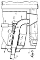
- such a machine generally comprises a lower bowl 1 which is disposed inside a fixed confinement envelope 2 and which is integral with the base of a vertical shaft 3 driven in rotation by a motor 4 with the interposition of a ball joint system 5 which allows the assembly to orient itself freely under the effect of the imbalances caused by the high speed rotation of the bowl 1.
- the shaft 3 crosses the slab or protective screen 6 which supports the fixed casing 2, through a removable plug 7 which is itself secured to an internal tank 8 intended when feeding the rotating bowl 1.
- the discharge of the liquid loaded into the tank 8 is effected by means of a pouring spout 9 mounted telescopically sliding on the end of the supply pipe 10.
- the axial displacement of the spout 9 under the effect of a control mechanism 11 supported either by the slab 6 or by a removable plug 12 engaged in a vertical housing thereof, makes it possible in one direction to bring the free end of the spout 9 above the interior space of the tank 8 avoiding any risk of untimely flow of the liquid loaded in the lower part of the casing 2 at the level of which the purified liquid is collected and discharged (tubing referenced 13), while the sliding of this spout 9 in the opposite direction authorizes the withdrawal of the container 8 upwards with the assembly supported by the removable plug 7.
- a deformable metal bellows 14 is ordinarily used which ensures the confinement of the abovementioned connection without interfering with the axial sliding of the spout 9.
- this bellows 14 poses problems which are difficult to solve. If its thickness is too small, its damage by mechanical shock or by corrosion can occur very quickly, thereby generating the leaks that it was desired to avoid, while if this thickness is intended to be large enough to overcome the aforementioned drawback, the operation of the control mechanism 11 associated with the spout 9 becomes difficult and gives rise to risks of errors in positioning the spout or to damage. We are therefore naturally led to adopt a compromise which in fact satisfies neither of the two imperatives.
- the present invention proposes to solve the problem by eliminating outright the protective metal bellows usually associated with the spout.
- a centrifugal decanter according to the invention is characterized by the elements of the characterizing part of claim 1.
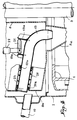
- the retractable spout is mounted with axial sliding in a sleeve carried inside the fixed confinement envelope by a vertical wall integral with the removable plug traversed by the drive shaft of the bowl, the displacement of this spout in one direction or in the other under the action of its control mechanism suspended from said plug having the effect of either engaging its upstream end on the outlet of the supply pipe in the fixed casing with a view to pouring into the bowl of the liquid responsible for processing, or to clear said end of this outlet to allow the extraction of the aforementioned plug and the rotating assembly of the machine.
- fig. 1 schematically illustrates the general arrangement of a decanter of the conventional type.
- Fig. 2 similarly shows the arrangement of a decanter established in accordance with the invention.
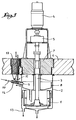
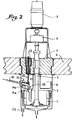
- Fig. 3 and 4 are axial sections on a larger scale representing the spout retractable to the two positions of use.
- the end of the pipe 10 is engaged with the end, advantageously swollen to recover any accidental overflow, of a sliding pouring spout, here referenced 19 and assumed to have an angled profile in order to penetrate its downstream end into the flared top of the vertical tube 8 a of the internal tank 8.
- This spout 19 is guided axially inside an oblique sleeve 20 made integral with the side wall 8 b of the tank 8, and it is also integral with two fins vertical 19 a which are turned upwards to form bearings for an eccentric 21; the latter is fixed on the base of the rotating operating shaft 22 of the control mechanism as in fig. 2 it was assumed, as in the prior art, to be carried by an independent stopper 12, it being however observed that in the case of FIG. 2 this plug 12 is housed, no longer in the slab 6 as in fig. 1, but in the removable cap 7.
- the berser spout 19 with an elastic return system in the released position according to FIG. 4.
- This system can in particular comprise a spring 23 interposed between an outer flange 19 b of the spout 19 and an inner flange 20 a of the sleeve 20.
- the invention is capable of being applied to centrifugal decanters in which the internal feed tank 8 is replaced by a box forming a core to limit the volume of liquid liable to accumulate in the envelope. 2 in case of untimely blockage.
Landscapes
- Centrifugal Separators (AREA)
Claims (4)
Applications Claiming Priority (2)
| Application Number | Priority Date | Filing Date | Title |
|---|---|---|---|
| FR8717860A FR2624764B1 (fr) | 1987-12-16 | 1987-12-16 | Decanteuse centrifuge a bec d'alimentation retractable |
| FR8717860 | 1987-12-16 |
Publications (3)
| Publication Number | Publication Date |
|---|---|
| EP0321365A2 EP0321365A2 (de) | 1989-06-21 |
| EP0321365A3 EP0321365A3 (en) | 1990-03-07 |
| EP0321365B1 true EP0321365B1 (de) | 1992-02-26 |
Family
ID=9358118
Family Applications (1)
| Application Number | Title | Priority Date | Filing Date |
|---|---|---|---|
| EP88420415A Expired - Lifetime EP0321365B1 (de) | 1987-12-16 | 1988-12-12 | Dekantierzentrifuge mit einziehbarer Zuführvorrichtung |
Country Status (5)
| Country | Link |
|---|---|
| US (1) | US4869713A (de) |
| EP (1) | EP0321365B1 (de) |
| JP (1) | JPH01297160A (de) |
| DE (1) | DE3868607D1 (de) |
| FR (1) | FR2624764B1 (de) |
Families Citing this family (2)
| Publication number | Priority date | Publication date | Assignee | Title |
|---|---|---|---|---|
| FR2706216B1 (fr) * | 1993-06-07 | 1995-07-21 | Robatel Slpi | Décanteuse continue pour le traitement des produits nucléaires. |
| US11318480B2 (en) * | 2019-03-04 | 2022-05-03 | Kennametal Inc. | Centrifuge feed pipes and associated apparatus |
Family Cites Families (8)
| Publication number | Priority date | Publication date | Assignee | Title |
|---|---|---|---|---|
| US1927822A (en) * | 1926-02-16 | 1933-09-26 | Merco Centrifugal Separator Co | Centrifuge apparatus |
| US3073516A (en) * | 1959-08-06 | 1963-01-15 | Dorr Oliver Inc | Centrifuges |
| US3893907A (en) * | 1973-09-10 | 1975-07-08 | Exxon Research Engineering Co | Method and apparatus for the treatment of tar sand froth |
| JPS5365587A (en) * | 1976-11-24 | 1978-06-12 | Fujitsu Ltd | Reciprocal motion driving device |
| FR2560071B1 (fr) * | 1978-12-19 | 1987-01-16 | Commissariat Energie Atomique | Centrifugeuse pendulaire de decantation |
| JPS5845759A (ja) * | 1981-09-11 | 1983-03-17 | Toshiba Corp | 遠心清澄機 |
| US4406651A (en) * | 1982-04-15 | 1983-09-27 | Donaldson Company, Inc. | Multi-phase self purging centrifuge |
| GB8517762D0 (en) * | 1985-07-15 | 1985-08-21 | British Nuclear Fuels Plc | Centrifuges |
-
1987
- 1987-12-16 FR FR8717860A patent/FR2624764B1/fr not_active Expired - Fee Related
-
1988
- 1988-12-05 JP JP63307666A patent/JPH01297160A/ja active Pending
- 1988-12-07 US US07/280,819 patent/US4869713A/en not_active Expired - Fee Related
- 1988-12-12 EP EP88420415A patent/EP0321365B1/de not_active Expired - Lifetime
- 1988-12-12 DE DE8888420415T patent/DE3868607D1/de not_active Expired - Fee Related
Also Published As
| Publication number | Publication date |
|---|---|
| DE3868607D1 (de) | 1992-04-02 |
| FR2624764A1 (fr) | 1989-06-23 |
| FR2624764B1 (fr) | 1990-05-18 |
| JPH01297160A (ja) | 1989-11-30 |
| EP0321365A2 (de) | 1989-06-21 |
| US4869713A (en) | 1989-09-26 |
| EP0321365A3 (en) | 1990-03-07 |
Similar Documents
| Publication | Publication Date | Title |
|---|---|---|
| FR2790510A1 (fr) | Procede et dispositif de controle de debit en fond de puits, a commande decouplee | |
| EP0628970A1 (de) | Decantierzentrifuge zur Behandlung von nuklearen Produkten | |
| EP0712654A2 (de) | Vorrichtung zum Trennen und Filtern von Partikeln aus einem strömenden fluiden Medium | |
| EP0143063B1 (de) | Anbohrvorrichtung für druckbeaufschlagte Flüssigkeitsleitungen | |
| EP0037334A1 (de) | Absperrventilvorrichtung mit Überdrucksicherung | |
| EP0435716B1 (de) | Vorrichtung zur Separation eines Gas-Flüssigkeitsgemisches als Zufuhr einer Imbohrlochpumpe | |
| EP0321365B1 (de) | Dekantierzentrifuge mit einziehbarer Zuführvorrichtung | |
| FR2652610A1 (fr) | Procede de pompage de melange liquide gaz dans un puits d'extraction petrolier et dispositif de mise en óoeuvre du procede. | |
| FR2895271A1 (fr) | Organe de deversement d'une enceinte de traitement, notamment d'hydrocarbures, et enceinte correspondant | |
| EP2354002A1 (de) | Verfahren und Vorrichtung zum Leeren eines Tanks, Tank und mit einer solchen Vorrichtung ausgestattetes Luftfahrzeug | |
| FR3082552A1 (fr) | Turbomachine d'aeronef a double flux comprenant un reservoir de lubrifiant dans un compartiment inter-veines, ainsi que des moyens ameliores de remplissage du reservoir | |
| EP0428433B1 (de) | Vorrichtung zum Fixieren der Steuerstabsführungsplatte im Kernreaktordruckgefäss | |
| EP1939457B1 (de) | Pumpe mit elastischer Vorrichtung auf einem Lager | |
| FR2684562A1 (fr) | Appareillage de recyclage de solvants. | |
| EP0437394B1 (de) | Rührerantreibungseinheit, insbesondere ein MischerDekantierapparat zur Verwendung in einer Vorrichtung zur Wiederaufarbeitung von Kernbrennstoffen | |
| EP0097548A1 (de) | Bohrlochpumpe und Verfahren zu ihrem Schutz | |
| CH624506A5 (de) | ||
| CA1205753A (fr) | Tamiseur pour la separation de particules solides contenues dans un liquide | |
| FR2571983A1 (fr) | Appareil centrifugateur de contact pour extraction au moyen de solvants | |
| EP2548206B1 (de) | Verstopfungsvorrichtung zum verstopfen einer rohrleitung für eine flüssigkeit, beispielsweise zum einsatz in einer kernreaktoranlage, insbesondere in verbindung mit einer an der bodenseite eines dampferzeugers angebrachten abflussleitung | |
| FR2531257A1 (fr) | Element combustible de reacteur nucleaire | |
| EP1836028A1 (de) | Angetriebene betätigungsvorrichtung für handschuhfach und damit ausgestattetes handschuhfach | |
| FR3018576A1 (fr) | Dispositif passif de distribution de fluide et ensemble comportant un tel dispositif | |
| EP0394127B1 (de) | Expandierbarer Ring für dichte Befestigung einer Schutzmanschette in einer Öffnung | |
| CA3090311A1 (fr) | Architecture de reacteur nucleaire integre limitant les contraintes appliquees aux mecanismes integres |
Legal Events
| Date | Code | Title | Description |
|---|---|---|---|
| PUAI | Public reference made under article 153(3) epc to a published international application that has entered the european phase |
Free format text: ORIGINAL CODE: 0009012 |
|
| AK | Designated contracting states |
Kind code of ref document: A2 Designated state(s): DE GB |
|
| PUAL | Search report despatched |
Free format text: ORIGINAL CODE: 0009013 |
|
| AK | Designated contracting states |
Kind code of ref document: A3 Designated state(s): DE GB |
|
| 17P | Request for examination filed |
Effective date: 19900414 |
|
| 17Q | First examination report despatched |
Effective date: 19910402 |
|
| RAP1 | Party data changed (applicant data changed or rights of an application transferred) |
Owner name: ROBATEL |
|
| GRAA | (expected) grant |
Free format text: ORIGINAL CODE: 0009210 |
|
| AK | Designated contracting states |
Kind code of ref document: B1 Designated state(s): DE GB |
|
| REF | Corresponds to: |
Ref document number: 3868607 Country of ref document: DE Date of ref document: 19920402 |
|
| GBT | Gb: translation of ep patent filed (gb section 77(6)(a)/1977) | ||
| PLBE | No opposition filed within time limit |
Free format text: ORIGINAL CODE: 0009261 |
|
| STAA | Information on the status of an ep patent application or granted ep patent |
Free format text: STATUS: NO OPPOSITION FILED WITHIN TIME LIMIT |
|
| 26N | No opposition filed | ||
| PGFP | Annual fee paid to national office [announced via postgrant information from national office to epo] |
Ref country code: GB Payment date: 19961206 Year of fee payment: 9 |
|
| PGFP | Annual fee paid to national office [announced via postgrant information from national office to epo] |
Ref country code: DE Payment date: 19970121 Year of fee payment: 9 |
|
| PG25 | Lapsed in a contracting state [announced via postgrant information from national office to epo] |
Ref country code: GB Free format text: LAPSE BECAUSE OF NON-PAYMENT OF DUE FEES Effective date: 19971212 |
|
| GBPC | Gb: european patent ceased through non-payment of renewal fee |
Effective date: 19971212 |
|
| PG25 | Lapsed in a contracting state [announced via postgrant information from national office to epo] |
Ref country code: DE Free format text: LAPSE BECAUSE OF NON-PAYMENT OF DUE FEES Effective date: 19980901 |