EP0321205B1 - Container for use by travelling sales person - Google Patents
Container for use by travelling sales person Download PDFInfo
- Publication number
- EP0321205B1 EP0321205B1 EP88311820A EP88311820A EP0321205B1 EP 0321205 B1 EP0321205 B1 EP 0321205B1 EP 88311820 A EP88311820 A EP 88311820A EP 88311820 A EP88311820 A EP 88311820A EP 0321205 B1 EP0321205 B1 EP 0321205B1
- Authority
- EP
- European Patent Office
- Prior art keywords
- bag
- vertical column
- display stand
- display
- state
- Prior art date
- Legal status (The legal status is an assumption and is not a legal conclusion. Google has not performed a legal analysis and makes no representation as to the accuracy of the status listed.)
- Expired - Lifetime
Links
Images


Classifications
-
- A—HUMAN NECESSITIES
- A45—HAND OR TRAVELLING ARTICLES
- A45C—PURSES; LUGGAGE; HAND CARRIED BAGS
- A45C9/00—Purses, Luggage or bags convertible into objects for other use
Definitions
- the present invention relates to bags, suitcases or other similar containers for use by travelling sales persons in transporting goods from one retail outlet to another.
- An object of the present invention is to overcome the above difficulties and to provide the sales person with a means for displaying sales goods more quickly and conveniently and to better effect.
- US-A-2,476,932 discloses a travelling container with a display stand secured therein and movable between a collapsed state within the container for transportation purposes and an erect state projecting from the container for display purposes.
- the present invention is characterised in that the display stand is a garment display stand comprising a base, a single multisectional vertical column which is telescopic between a collapsed contracted state and an erect extended state and a horizontal rail mounted centrally at the top of the column, there being locking means biassed into a locking position for securing each of the sections of the vertical column to a next section when the vertical column is brought from its collapsed state to its erect state, the locking means being releasable to allow contraction of the multisectional vertical column.
- a garment display stand of the above type allow the sales person to display garments to the retailer in a manner similar to the manner in which the retailer would in turn display the garments to customers. Furthermore, the garment display stand of the above type occupies very little of the internal volume of the bag.
- the horizontal rail is telescopic from a contracted state in which, with the vertical column also contracted, the display stand fits entirely into the bag, to an extended state in which, with the vertical column also extended, the horizontal display rail projects beyond the dimensions of the bag increasing the effective size of the display stand.
- the garments may be densely packed one against the other all along the length of the contracted horizontal rail so as to fill the bag with garments, and for display purposes the garments may be spaced apart along the extended rail to allow individual garments to be viewed.
- the locking means comprises a plurality of spring loaded plungers one of which is fixed on the lowermost of any pair of interengaging sections of the vertical column and the walls of the sections of the vertical column are provided with a plurality of apertures, each aperture being adapted to receive and engage with the plunger of the locking means to retain the telescopic vertical column at one of a number of preselected heights on extension of the said vertical column.
- the bag consists of flexible walls and a three dimensional open frame for supporting the walls when the container is to be used in the transportation or display mode, the open frame being capable of being collapsed or disassembled into two dimensions, and the display stand may also be capable of collapsing further beyond the storage mode or of being disassembled into two dimensions.
- the container can then be conveniently stored when not in use by collapsing or disassembling the open frame and the display stand into two dimensions and storing these in the bag, the walls of which also collapse when not supported by the open frame.
- castors may be provided on the bag to enable the bag to be wheeled by a user.
- the container comprises a bag 1 and a garment display stand comprising a base 2, a vertical support column 3 which is telescopic, and a horizontal display rail 4 which is also telescopic.
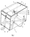
- Figure 1 shows the container in the transportation mode.
- the vertical support column 3 is in the contracted state.
- the horizontal display rail 4 is also in the contracted state.
- the garments have been omitted from the drawings for clarity, but in the transportation mode the garments are mounted on garment hangers (also omitted) suspended from the horizontal display rail 4, and the garments are densely packed one against the other.
- the flap 5 of the bag 1 is folded over and is closed by means of a zip fastener 6.
- the bag 1 may be carried by the sales person by means of handles 7. Alternatively, the bag 1 may be pulled from place to place by the sales person by means of strap 8, with the bag rolling on castors 9.
- the bag 1 is of a suitable size to fit into the trunk of a car.
- Figure 2 shows the container in the display mode.
- the sales person simply unzips the flap 5 and moves it to the open position, and then pulls the horizontal display rail 4 upwardly thus extending the vertical support column 3.
- the garments are now on view to the retailer.
- the sales person may extend the horizontal display rail 4 telescopically from the contracted state shown in Figure 2 to an extended state thereby allowing more space on the rail.
- the garments on each side of that garment may be pushed away along the rail 4 so as to allow better viewing.
- the sales person When viewing has been completed the sales person first pushes all the garments back together onto the central section of the telescopic horizontal display rail 4, then telescopes the horizontal rail 4 to its contracted state, and then operates the securing mechanisms 10a, 10b and 10c in sequence to allow the vertical column 3 to telescope to its contracted state within the bag 1, and finally folds over the flap 5 and secures it in the closed position by means of the zip fastener 6.
- Figure 3 shows the display stand disassembled when it is not required for transportation or display purposes. It will be seen that the display stand can be disassembled into three smaller sub-assemblies, namely the base 2, the vertical support column 3 and the horizontal display rail 4 and uppermost telescopic section of the column 3, each of which sub-assemblies is generally planar. The sub-assemblies can be placed in the bag 1. The bag 1 can also be collapsed to a flat state. Collapsing of the bag 1 is effected by removing and collapsing the internal frame 11. Figure 1 shows some but not all of the elements of the frame 11. The disassembled display stand and the collapsed internal frame 11 can then be put in the bag 1.
- Each securing mechanism comprises a spring loaded plunger 12 near the top of one telescopic section and a complementary socket near the bottom of the next section.
- the telescopic section may be lowered again by withdrawing the plunger 12 against the spring bias. In this way the vertical column 3 may be extended or contracted in a stepwise manner.
- the base 2 of the display stand has a seat 14 for receiving and locating the lower end of the vertical column 3.
- the seat 14 is recessed thereby preventing the vertical column 3 rotating and thus unscrewing from the base 2.
- the base 2 comprises four feet 15 each of which is provided with a downwardly facing socket 16 for receiving the screw threaded shank of a castor 9.
- the shank of each castor 9 extends upwardly through a castor protection plate 17 (see Figure 3) immediately above the castor, through an eye in the single continuous strip of material which forms the two handles 8, through an eye in the material of the bag 1 and into the socket 16.
- the bag 1 is provided on the inside end faces with pockets (not shown) for receiving sales literature.
- the base of the display stand may comprise a rectangular board (not shown).
- the construction according to the invention may also be used by a traveller to transport the traveller's personal clothing.
- a traveller may use the container to transport business suits and shirts.
Abstract
Description
- The present invention relates to bags, suitcases or other similar containers for use by travelling sales persons in transporting goods from one retail outlet to another.
- One particular difficulty which travelling sales persons experience when visiting retail outlets for the purpose of selling their goods, especially large items such as garments, textiles, carpets or shoes, is that at each retail outlet they must unpack the contents of the bag or suitcase, lay out the goods on a counter or other surface for display purposes, and subsequently repack the goods. Unpacking and repacking is time consuming and laborious. Furthermore, it is often inconvenient to occupy a counter or other surface, as the retailer may want to make use of the limited counter space to sell his goods to customers.
- An object of the present invention is to overcome the above difficulties and to provide the sales person with a means for displaying sales goods more quickly and conveniently and to better effect.
- US-A-2,476,932 (Tucker) discloses a travelling container with a display stand secured therein and movable between a collapsed state within the container for transportation purposes and an erect state projecting from the container for display purposes.
- The present invention is characterised in that the display stand is a garment display stand comprising a base, a single multisectional vertical column which is telescopic between a collapsed contracted state and an erect extended state and a horizontal rail mounted centrally at the top of the column, there being locking means biassed into a locking position for securing each of the sections of the vertical column to a next section when the vertical column is brought from its collapsed state to its erect state, the locking means being releasable to allow contraction of the multisectional vertical column.
- The use of a garment display stand of the above type allow the sales person to display garments to the retailer in a manner similar to the manner in which the retailer would in turn display the garments to customers. Furthermore, the garment display stand of the above type occupies very little of the internal volume of the bag.
- Advantageously, the horizontal rail is telescopic from a contracted state in which, with the vertical column also contracted, the display stand fits entirely into the bag, to an extended state in which, with the vertical column also extended, the horizontal display rail projects beyond the dimensions of the bag increasing the effective size of the display stand.
- As a result of the telescopic nature of the horizontal rail, for transportation purposes the garments may be densely packed one against the other all along the length of the contracted horizontal rail so as to fill the bag with garments, and for display purposes the garments may be spaced apart along the extended rail to allow individual garments to be viewed.
- Preferably, the locking means comprises a plurality of spring loaded plungers one of which is fixed on the lowermost of any pair of interengaging sections of the vertical column and the walls of the sections of the vertical column are provided with a plurality of apertures, each aperture being adapted to receive and engage with the plunger of the locking means to retain the telescopic vertical column at one of a number of preselected heights on extension of the said vertical column.
- Advantageously, the bag consists of flexible walls and a three dimensional open frame for supporting the walls when the container is to be used in the transportation or display mode, the open frame being capable of being collapsed or disassembled into two dimensions, and the display stand may also be capable of collapsing further beyond the storage mode or of being disassembled into two dimensions.
- The container can then be conveniently stored when not in use by collapsing or disassembling the open frame and the display stand into two dimensions and storing these in the bag, the walls of which also collapse when not supported by the open frame.
- For convenience, castors may be provided on the bag to enable the bag to be wheeled by a user.
- The invention will now be described more particularly with reference to the accompanying drawings which show, by way of example only, one embodiment of container according to the invention, comprising a bag and display stand. In the drawings:
- Figure 1
- is a perspective view of the bag in the transportation mode, that is to say closed and with the garment display stand (shown in dashed lines) in the collapsed state entirely within the bag;
- Figure 2
- is a similar view of the bag in the display mode, that is to say open and with the garment display stand in the erect state projecting up from the bag;
- Figure 3
- is an exploded perspective view of the garment display stand, showing how it may be disassembled for storage when it is not being used for transportation or display;
- Figure 4
- is a side elevation of the bag in the transportation mode; and
- Figure 5
- is a sectional elevation on a much larger scale of a detail of the telescopic mechanism.
- Referring now to the drawings, the container comprises a bag 1 and a garment display stand comprising a
base 2, avertical support column 3 which is telescopic, and a horizontal display rail 4 which is also telescopic. - Figure 1 shows the container in the transportation mode. The
vertical support column 3 is in the contracted state. The horizontal display rail 4 is also in the contracted state. The garments have been omitted from the drawings for clarity, but in the transportation mode the garments are mounted on garment hangers (also omitted) suspended from the horizontal display rail 4, and the garments are densely packed one against the other. Theflap 5 of the bag 1 is folded over and is closed by means of azip fastener 6. The bag 1 may be carried by the sales person by means ofhandles 7. Alternatively, the bag 1 may be pulled from place to place by the sales person by means ofstrap 8, with the bag rolling oncastors 9. The bag 1 is of a suitable size to fit into the trunk of a car. - Figure 2 shows the container in the display mode. At a retail outlet the sales person simply unzips the
flap 5 and moves it to the open position, and then pulls the horizontal display rail 4 upwardly thus extending thevertical support column 3. The garments are now on view to the retailer. In order to allow the retailer to view an individual garment, the sales person may extend the horizontal display rail 4 telescopically from the contracted state shown in Figure 2 to an extended state thereby allowing more space on the rail. In particular, when the retailer wishes to view a particular garment, the garments on each side of that garment may be pushed away along the rail 4 so as to allow better viewing. When viewing has been completed the sales person first pushes all the garments back together onto the central section of the telescopic horizontal display rail 4, then telescopes the horizontal rail 4 to its contracted state, and then operates thesecuring mechanisms vertical column 3 to telescope to its contracted state within the bag 1, and finally folds over theflap 5 and secures it in the closed position by means of thezip fastener 6. - Figure 3 shows the display stand disassembled when it is not required for transportation or display purposes. It will be seen that the display stand can be disassembled into three smaller sub-assemblies, namely the
base 2, thevertical support column 3 and the horizontal display rail 4 and uppermost telescopic section of thecolumn 3, each of which sub-assemblies is generally planar. The sub-assemblies can be placed in the bag 1. The bag 1 can also be collapsed to a flat state. Collapsing of the bag 1 is effected by removing and collapsing theinternal frame 11. Figure 1 shows some but not all of the elements of theframe 11. The disassembled display stand and the collapsedinternal frame 11 can then be put in the bag 1. - The
securing mechanisms plunger 12 near the top of one telescopic section and a complementary socket near the bottom of the next section. When a particular telescopic section is pulled upwards the socket at the bottom thereof comes into register with theplunger 12 at the top of the following telescopic section, and theplunger 12 engages in the socket preventing further relative movement. The telescopic section may be lowered again by withdrawing theplunger 12 against the spring bias. In this way thevertical column 3 may be extended or contracted in a stepwise manner. - Certain constructional details of the bag 1 and display stand will now be described. The
base 2 of the display stand has aseat 14 for receiving and locating the lower end of thevertical column 3. Theseat 14 is recessed thereby preventing thevertical column 3 rotating and thus unscrewing from thebase 2. Thebase 2 comprises fourfeet 15 each of which is provided with a downwardly facingsocket 16 for receiving the screw threaded shank of acastor 9. The shank of eachcastor 9 extends upwardly through a castor protection plate 17 (see Figure 3) immediately above the castor, through an eye in the single continuous strip of material which forms the twohandles 8, through an eye in the material of the bag 1 and into thesocket 16. The bag 1 is provided on the inside end faces with pockets (not shown) for receiving sales literature. - In an alternative construction the base of the display stand may comprise a rectangular board (not shown).
- The construction according to the invention may also be used by a traveller to transport the traveller's personal clothing. For example a business traveller may use the container to transport business suits and shirts.
Claims (5)
- A container, for example a bag (1) or suitcase, for use by a travelling sales person in transporting goods from one retail outlet to another provided with a display stand movable between a collapsed state within the bag (1) for transportation purposes and an erect state projecting from the bag (1) for display purposes, characterised in that the display stand is a garment display stand comprising a base (2), a single multisectional vertical column (3) which is telescopic between a collapsed contracted state and an erect extended state and a horizontal rail (4) mounted centrally at the top of the column (3), there being locking means (10a, 10b, 10c) biassed into a locking position for securing each of the sections of the vertical column (3) to a next section when the vertical column (3) is brought from its collapsed state to its erect state, the locking means being releasable to allow contraction of the multisectional vertical column (3).
- A container according to claim 1, characterised in that the horizontal rail (4) is telescopic from a contracted state in which, with the vertical column also contracted, the display stand fits entirely into the bag (1), to an extended state in which, with the vertical column (3) also extended, the horizontal display rail (4) projects beyond the dimensions of the bag (1) increasing the effective size of the display stand.
- A container according to claim 1 or claim 2, characterised in that the bag (1) consists of flexible walls and a three dimensional open frame (11) for supporting the walls when the container is to be used in the transportation or display mode, the open frame (11) being capable of being collapsed or disassembled into two dimensions, and the display stand may also be capable of collapsing further beyond the storage mode or of being disassembled into two dimensions.
- A container according to any one of the preceding claims, characterised in that the locking means (10a, 10b, 10c) comprises a plurality of spring loaded plungers (12) one of which is fixed on the lowermost of any pair of interengaging sections of the vertical column (3) and the walls of the sections of the vertical column (3) are provided with a plurality of apertures, each aperture being adapted to receive and engage with the plunger (12) of the locking means (10a, 10b, 10c) to retain the telescopic vertical column (3) at one of a number of preselected heights on extension of the said vertical column (3).
- A container according to any one of the preceding claims, characterised in that castors (9) are provided on the bag to enable the bag to be wheeled by a user.
Priority Applications (1)
| Application Number | Priority Date | Filing Date | Title |
|---|---|---|---|
| AT88311820T ATE90528T1 (en) | 1987-12-14 | 1988-12-14 | CONTAINER FOR SALESMAN. |
Applications Claiming Priority (3)
| Application Number | Priority Date | Filing Date | Title |
|---|---|---|---|
| IE296287A IE60729B1 (en) | 1987-12-14 | 1987-12-14 | "Container for use by travelling sales person" |
| IE296287 | 1987-12-14 | ||
| CA000585566A CA1325796C (en) | 1987-12-14 | 1988-12-09 | Container for use by travelling sales person |
Publications (3)
| Publication Number | Publication Date |
|---|---|
| EP0321205A2 EP0321205A2 (en) | 1989-06-21 |
| EP0321205A3 EP0321205A3 (en) | 1989-09-20 |
| EP0321205B1 true EP0321205B1 (en) | 1993-06-16 |
Family
ID=25672290
Family Applications (1)
| Application Number | Title | Priority Date | Filing Date |
|---|---|---|---|
| EP88311820A Expired - Lifetime EP0321205B1 (en) | 1987-12-14 | 1988-12-14 | Container for use by travelling sales person |
Country Status (6)
| Country | Link |
|---|---|
| EP (1) | EP0321205B1 (en) |
| AT (1) | ATE90528T1 (en) |
| CA (1) | CA1325796C (en) |
| DE (1) | DE3881849T2 (en) |
| IE (1) | IE60729B1 (en) |
| ZA (1) | ZA889342B (en) |
Families Citing this family (2)
| Publication number | Priority date | Publication date | Assignee | Title |
|---|---|---|---|---|
| NL1006523C2 (en) * | 1997-07-09 | 1999-01-12 | Gaalen Georgius J J Van | Suitcase for traveling salesmen features clothes rack inside |
| GB2457883A (en) * | 2008-02-26 | 2009-09-02 | Hannah Nicole Beaumont | A suitcase with an extendable garment support |
Citations (1)
| Publication number | Priority date | Publication date | Assignee | Title |
|---|---|---|---|---|
| US2476932A (en) * | 1947-09-27 | 1949-07-19 | Arthur C Tucker | Traveling case having divided fabric cover and extensible support for garment hangers |
Family Cites Families (4)
| Publication number | Priority date | Publication date | Assignee | Title |
|---|---|---|---|---|
| DE229087C (en) * | ||||
| CH29517A (en) * | 1903-09-17 | 1904-08-31 | Willy Wohlrabe | Suitcase convertible into a clothes rack |
| CH60886A (en) * | 1912-05-28 | 1913-09-01 | Anita Kinen | Travel coat rack |
| GB890964A (en) * | 1959-05-03 | 1962-03-07 | Robert Fitzhugh Hillas Drake | Improvements relating to baggage |
-
1987
- 1987-12-14 IE IE296287A patent/IE60729B1/en not_active IP Right Cessation
-
1988
- 1988-12-09 CA CA000585566A patent/CA1325796C/en not_active Expired - Fee Related
- 1988-12-14 AT AT88311820T patent/ATE90528T1/en not_active IP Right Cessation
- 1988-12-14 ZA ZA889342A patent/ZA889342B/en unknown
- 1988-12-14 EP EP88311820A patent/EP0321205B1/en not_active Expired - Lifetime
- 1988-12-14 DE DE88311820T patent/DE3881849T2/en not_active Expired - Fee Related
Patent Citations (1)
| Publication number | Priority date | Publication date | Assignee | Title |
|---|---|---|---|---|
| US2476932A (en) * | 1947-09-27 | 1949-07-19 | Arthur C Tucker | Traveling case having divided fabric cover and extensible support for garment hangers |
Also Published As
| Publication number | Publication date |
|---|---|
| EP0321205A3 (en) | 1989-09-20 |
| IE872962L (en) | 1989-06-14 |
| ATE90528T1 (en) | 1993-07-15 |
| DE3881849D1 (en) | 1993-07-22 |
| DE3881849T2 (en) | 1994-01-20 |
| EP0321205A2 (en) | 1989-06-21 |
| ZA889342B (en) | 1989-09-27 |
| CA1325796C (en) | 1994-01-04 |
| IE60729B1 (en) | 1994-08-10 |
Similar Documents
| Publication | Publication Date | Title |
|---|---|---|
| US4982820A (en) | Container for use by travelling sales person | |
| US5400494A (en) | Method of manufacturing a wheeled garment bag | |
| US5630521A (en) | Ergonomic upright wheeled luggage | |
| EP0804105B1 (en) | Ergonomic upright wheeled luggage | |
| US20110120826A1 (en) | Portable costume case with a collapsible rack | |
| CA1216827A (en) | Wheeled garment bag | |
| US4953878A (en) | Collapsible cart | |
| US3746358A (en) | Hand cart for stacking goods in interlocking relationship | |
| US20050284717A1 (en) | Wheeled suitcase with detachable garment holder and method of use thereof | |
| US11001285B1 (en) | Multi-functional utility cart and method of use | |
| US20090321204A1 (en) | Convertible luggage and dressing station | |
| EP3507167B1 (en) | Mobile storage unit | |
| US20060137949A1 (en) | Shoe case | |
| US20090224495A1 (en) | Collapsible shopping caddy | |
| EP0321205B1 (en) | Container for use by travelling sales person | |
| EP0260094B1 (en) | Utility bag | |
| US2754945A (en) | Hand luggage | |
| US2841257A (en) | Luggage for carrying apparel without folding | |
| US2338401A (en) | Garment carrying frame | |
| US20060288917A1 (en) | Tall portable locker table with embedded peg hanger | |
| EP0281478A2 (en) | Articles of luggage for arranging and carrying any goods, in particular for use at home, at school, or when travelling | |
| GB2546125A (en) | Organizer | |
| US20110083932A1 (en) | Garment organizing system,assembly, and method | |
| KR200326974Y1 (en) | Shopping Bag | |
| KR200471316Y1 (en) | Carrying cart with cooling and chair functions |
Legal Events
| Date | Code | Title | Description |
|---|---|---|---|
| PUAI | Public reference made under article 153(3) epc to a published international application that has entered the european phase |
Free format text: ORIGINAL CODE: 0009012 |
|
| AK | Designated contracting states |
Kind code of ref document: A2 Designated state(s): AT BE CH DE ES FR GB GR IT LI LU NL SE |
|
| PUAL | Search report despatched |
Free format text: ORIGINAL CODE: 0009013 |
|
| AK | Designated contracting states |
Kind code of ref document: A3 Designated state(s): AT BE CH DE ES FR GB GR IT LI LU NL SE |
|
| 17P | Request for examination filed |
Effective date: 19900315 |
|
| 17Q | First examination report despatched |
Effective date: 19901109 |
|
| RAP1 | Party data changed (applicant data changed or rights of an application transferred) |
Owner name: EOLAS - THE IRISH SCIENCE AND TECHNOLOGY AGENCY |
|
| GRAA | (expected) grant |
Free format text: ORIGINAL CODE: 0009210 |
|
| AK | Designated contracting states |
Kind code of ref document: B1 Designated state(s): AT BE CH DE ES FR GB GR IT LI LU NL SE |
|
| PG25 | Lapsed in a contracting state [announced via postgrant information from national office to epo] |
Ref country code: SE Effective date: 19930616 Ref country code: NL Effective date: 19930616 Ref country code: LI Effective date: 19930616 Ref country code: GR Free format text: LAPSE BECAUSE OF FAILURE TO SUBMIT A TRANSLATION OF THE DESCRIPTION OR TO PAY THE FEE WITHIN THE PRESCRIBED TIME-LIMIT Effective date: 19930616 Ref country code: ES Free format text: THE PATENT HAS BEEN ANNULLED BY A DECISION OF A NATIONAL AUTHORITY Effective date: 19930616 Ref country code: CH Effective date: 19930616 Ref country code: BE Effective date: 19930616 Ref country code: AT Effective date: 19930616 |
|
| REF | Corresponds to: |
Ref document number: 90528 Country of ref document: AT Date of ref document: 19930715 Kind code of ref document: T |
|
| REF | Corresponds to: |
Ref document number: 3881849 Country of ref document: DE Date of ref document: 19930722 |
|
| ITF | It: translation for a ep patent filed |
Owner name: MODIANO & ASSOCIATI S.R |
|
| REG | Reference to a national code |
Ref country code: CH Ref legal event code: PL |
|
| ET | Fr: translation filed | ||
| NLV1 | Nl: lapsed or annulled due to failure to fulfill the requirements of art. 29p and 29m of the patents act | ||
| PG25 | Lapsed in a contracting state [announced via postgrant information from national office to epo] |
Ref country code: LU Free format text: LAPSE BECAUSE OF NON-PAYMENT OF DUE FEES Effective date: 19931231 |
|
| PLBE | No opposition filed within time limit |
Free format text: ORIGINAL CODE: 0009261 |
|
| STAA | Information on the status of an ep patent application or granted ep patent |
Free format text: STATUS: NO OPPOSITION FILED WITHIN TIME LIMIT |
|
| 26N | No opposition filed | ||
| REG | Reference to a national code |
Ref country code: GB Ref legal event code: 732E |
|
| ITPR | It: changes in ownership of a european patent |
Owner name: CAMBIO RAGIONE SOCIALE;FORFAS |
|
| REG | Reference to a national code |
Ref country code: FR Ref legal event code: TP |
|
| PGFP | Annual fee paid to national office [announced via postgrant information from national office to epo] |
Ref country code: GB Payment date: 19961129 Year of fee payment: 9 Ref country code: FR Payment date: 19961129 Year of fee payment: 9 |
|
| PGFP | Annual fee paid to national office [announced via postgrant information from national office to epo] |
Ref country code: DE Payment date: 19970226 Year of fee payment: 9 |
|
| PG25 | Lapsed in a contracting state [announced via postgrant information from national office to epo] |
Ref country code: GB Free format text: LAPSE BECAUSE OF NON-PAYMENT OF DUE FEES Effective date: 19971214 |
|
| PG25 | Lapsed in a contracting state [announced via postgrant information from national office to epo] |
Ref country code: FR Free format text: THE PATENT HAS BEEN ANNULLED BY A DECISION OF A NATIONAL AUTHORITY Effective date: 19971231 |
|
| GBPC | Gb: european patent ceased through non-payment of renewal fee |
Effective date: 19971214 |
|
| PG25 | Lapsed in a contracting state [announced via postgrant information from national office to epo] |
Ref country code: DE Free format text: LAPSE BECAUSE OF NON-PAYMENT OF DUE FEES Effective date: 19980901 |
|
| REG | Reference to a national code |
Ref country code: FR Ref legal event code: ST |
|
| PG25 | Lapsed in a contracting state [announced via postgrant information from national office to epo] |
Ref country code: IT Free format text: LAPSE BECAUSE OF NON-PAYMENT OF DUE FEES;WARNING: LAPSES OF ITALIAN PATENTS WITH EFFECTIVE DATE BEFORE 2007 MAY HAVE OCCURRED AT ANY TIME BEFORE 2007. THE CORRECT EFFECTIVE DATE MAY BE DIFFERENT FROM THE ONE RECORDED. Effective date: 20051214 |