EP0321167A2 - Schmierungssystem für Bremsen - Google Patents
Schmierungssystem für Bremsen Download PDFInfo
- Publication number
- EP0321167A2 EP0321167A2 EP88311724A EP88311724A EP0321167A2 EP 0321167 A2 EP0321167 A2 EP 0321167A2 EP 88311724 A EP88311724 A EP 88311724A EP 88311724 A EP88311724 A EP 88311724A EP 0321167 A2 EP0321167 A2 EP 0321167A2
- Authority
- EP
- European Patent Office
- Prior art keywords
- housing
- lubricant
- actuator according
- actuator
- tubular member
- Prior art date
- Legal status (The legal status is an assumption and is not a legal conclusion. Google has not performed a legal analysis and makes no representation as to the accuracy of the status listed.)
- Withdrawn
Links
Images

Classifications
-
- F—MECHANICAL ENGINEERING; LIGHTING; HEATING; WEAPONS; BLASTING
- F16—ENGINEERING ELEMENTS AND UNITS; GENERAL MEASURES FOR PRODUCING AND MAINTAINING EFFECTIVE FUNCTIONING OF MACHINES OR INSTALLATIONS; THERMAL INSULATION IN GENERAL
- F16N—LUBRICATING
- F16N19/00—Lubricant containers for use in lubricators or lubrication systems
-
- F—MECHANICAL ENGINEERING; LIGHTING; HEATING; WEAPONS; BLASTING
- F16—ENGINEERING ELEMENTS AND UNITS; GENERAL MEASURES FOR PRODUCING AND MAINTAINING EFFECTIVE FUNCTIONING OF MACHINES OR INSTALLATIONS; THERMAL INSULATION IN GENERAL
- F16D—COUPLINGS FOR TRANSMITTING ROTATION; CLUTCHES; BRAKES
- F16D65/00—Parts or details
- F16D65/14—Actuating mechanisms for brakes; Means for initiating operation at a predetermined position
- F16D65/16—Actuating mechanisms for brakes; Means for initiating operation at a predetermined position arranged in or on the brake
- F16D65/22—Actuating mechanisms for brakes; Means for initiating operation at a predetermined position arranged in or on the brake adapted for pressing members apart, e.g. for drum brakes
-
- F—MECHANICAL ENGINEERING; LIGHTING; HEATING; WEAPONS; BLASTING
- F16—ENGINEERING ELEMENTS AND UNITS; GENERAL MEASURES FOR PRODUCING AND MAINTAINING EFFECTIVE FUNCTIONING OF MACHINES OR INSTALLATIONS; THERMAL INSULATION IN GENERAL
- F16N—LUBRICATING
- F16N11/00—Arrangements for supplying grease from a stationary reservoir or the equivalent in or on the machine or member to be lubricated; Grease cups
- F16N11/04—Spring-loaded devices
-
- F—MECHANICAL ENGINEERING; LIGHTING; HEATING; WEAPONS; BLASTING
- F16—ENGINEERING ELEMENTS AND UNITS; GENERAL MEASURES FOR PRODUCING AND MAINTAINING EFFECTIVE FUNCTIONING OF MACHINES OR INSTALLATIONS; THERMAL INSULATION IN GENERAL
- F16N—LUBRICATING
- F16N21/00—Conduits; Junctions; Fittings for lubrication apertures
- F16N21/02—Lubricating nipples
-
- F—MECHANICAL ENGINEERING; LIGHTING; HEATING; WEAPONS; BLASTING
- F16—ENGINEERING ELEMENTS AND UNITS; GENERAL MEASURES FOR PRODUCING AND MAINTAINING EFFECTIVE FUNCTIONING OF MACHINES OR INSTALLATIONS; THERMAL INSULATION IN GENERAL
- F16D—COUPLINGS FOR TRANSMITTING ROTATION; CLUTCHES; BRAKES
- F16D2125/00—Components of actuators
- F16D2125/18—Mechanical mechanisms
- F16D2125/20—Mechanical mechanisms converting rotation to linear movement or vice versa
- F16D2125/22—Mechanical mechanisms converting rotation to linear movement or vice versa acting transversely to the axis of rotation
- F16D2125/28—Cams; Levers with cams
- F16D2125/30—Cams; Levers with cams acting on two or more cam followers, e.g. S-cams
-
- F—MECHANICAL ENGINEERING; LIGHTING; HEATING; WEAPONS; BLASTING
- F16—ENGINEERING ELEMENTS AND UNITS; GENERAL MEASURES FOR PRODUCING AND MAINTAINING EFFECTIVE FUNCTIONING OF MACHINES OR INSTALLATIONS; THERMAL INSULATION IN GENERAL
- F16D—COUPLINGS FOR TRANSMITTING ROTATION; CLUTCHES; BRAKES
- F16D2125/00—Components of actuators
- F16D2125/18—Mechanical mechanisms
- F16D2125/44—Mechanical mechanisms transmitting rotation
- F16D2125/56—Shafts for transmitting torque directly
Definitions
- This invention relates to a brake actuator incorporating a lubrication system and is particularly concerned with an improved system for lubricating the actuating mechanism of a cam actuated shoe drum brake.
- brake actuating mechanisms It is common practice for brake actuating mechanisms to be provided with lubricating means which typically consist of one or more grease nipples through which grease may be injected into internal passageways which distribute the grease throughout the mechanism.
- lubricating means typically consist of one or more grease nipples through which grease may be injected into internal passageways which distribute the grease throughout the mechanism.
- the principal force - applying means is in the form of a cam or wedge
- the braking force is applied to one or more friction elements by way of sliding tappets which move between extended and retracted positions.
- tappets are often associated with automatic adjusters which operate to adjust the tappets outwardly in order to compensate for wear of the friction elements.
- Movement of the tappets during actuation and adjustment causes the internal volume of actuator housing to vary and the consequent pressure differences within the housing can lead to lubricant being forced from the housing, in the case of a decrease in housing volume, or to ingress of air to the housing, in the case of a volume increase, neither of which conditions is desirable.
- An object of the present invention is to provide an improved brake actuator in which the aforesaid undesirable conditions are alleviated or avoided.
- a brake actuator comprises a housing, force transmission means in the housing, a mechanical actuator operable via said force transmission means to apply a friction element to a rotary member to be braked, a cavity within said housing, means for the admission of lubricant into said cavity, relief means for emission of lubricant at a predetermined positive system lubricant pressure, and a compressible device acting in response to variations in the effective volume of said cavity during brake operation to maintain a positive system pressure in said cavity.
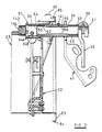
- FIG. 1 shows an internal shoe drum brake designated generally by the reference numeral 21.
- the brake 21 has a backing or torque plate 22 in which is formed a central opening 23 defining a flange in which openings 24 are formed for mounting the backing plate 22 on an axle assembly (not shown) of a vehicle in a known manner.
- axle assembly not shown
- a pair of brake shoes 25 and 26 Slidably supported relative to the backing plate 22 in a manner to be described, are a pair of brake shoes 25 and 26, each of which includes platform 27 carrying a friction lining material 29 and a transversley extending web 28.
- the friction linings 29 will move outwardly into frictional engagement with an associated brake drum (shown only partially in Figure 2 at 30) for braking rotation of the brake drum and an associated wheel.
- An actuator mechanism indicated generally by the reference numeral 31 is carried by the backplate for actuating the brake shoes 25 and 26 in a manner which will be described.
- the actuator mechanism 31 is interposed between one pair of adjacent ends of the brake shoe webs 28, and a fixed abutment assembly, indicated generally by the reference numeral 32, is disposed between the opposite pair of adjacent ends of the brake shoe webs 28.
- a formed return spring is carried by the fixed abutment 32 and cooperates with the brake shoes 25 and 26 so as to urge the brake shoes 25 and 26 towards their released or retracted positions.
- the actuator 31 comprises a cam 34 that is fixed to or formed integrally with the camshaft 35 rotably supported within a tubular member 36 for rotation about an axis parallel to and offset from the axis of rotation of the associated brake drum 30.
- the camshaft 35 has a serrated or splined end portion 37 which extends outwardly from beyond the tubular member 36 on the side of the backing plate 22 away from the brake shoes 25 and 26, and an actuating lever 38 is fixed on this end portion 37 by means of clamping bolt 39.
- a mounting bracket illustrated in a non-functional position and indicated generally by the reference numeral 41, is provided for carrying a power unit (not shown) such as an air chamber device for operating the lever 38 and rotating the camshaft 35 to actuate the brakes, in a manner to be described.
- the mounting bracket 41 may be conveniently formed, for example by pressing, from sheet metal and has a flange 46 adapted to carry a power unit (not shown) in use which is connected to the lever 38 for actuating the lever 38 and camshaft 35 in known manner.
- the cam 34 is contained within the actuator housing 54 in which the actuator mechanism 31 is contained.
- the actuator housing 54 is provided with a cylindrical bore 55 into which a reduced diameter end portion of the tubular member 36 opposite to the lever 38 is fitted.
- An O-ring seal 56 is contained at this joint to provide a fluid-tight seal.
- a dirt shield indicated generally by the reference numeral 83 is fixed to the rear surface of the backing plate 22.
- the dirt shield 83 has a re-entrant flange 84 that is adapted to receive the peripheral edge 85 of the brake drum 30, as shown in figure 2, so as to effect a relatively dirt-free assembly.
- tubular member 36 is then inserted over the camshaft 35 into the tight fitting bore of the backing plate 22 and into the bore 55 of the housing 54.
- the tubular member 36 is provided with spaced bushings or bearings 62 that rotatably journal the camshaft 35 at its opposite ends.
- a lip-type seal 63 is provided at the outer end of the tubular member 36 so as to prevent the ingress of foreign material to the interior of the housing assembly.
- the cam 34 is provided at opposed locations thereon with a pair of pockets, one of which can be seen at 34A, each of which receives respective ends of struts, one of which is seen at 34B in the pocket 34A, each strut cooperating with respective actuator tappets 105 and 106.
- the actuator tappets 105 and 106 are associated with the webs 27 of the brake shoes 25 and 26 and are slidably supported in respective bores of the housing 54, one of which is seen at 107, for achieving brake actuation.
- Each of the tappets 105 and 106 is of generally the same construction and comprises a first member 109 engaged at one end with one of the struts 34B and which has an externally threaded end portion received in an internally threaded bore 112 of a second tappet portion 113.
- Each tappet portion 113 has a cylindrical outer configuration that is slidably supported in the respective housing bore 107 and has a slotted end part that receives the adjacent end of the brake shoe webs 28.
- the tappet portions 113 are held against rotation.
- the portions 109 are, however, rotatable so as to achieve adjustment for wear.
- An automatic adjusting mechanism is incorporated for achieving this adjustment and is not described in detail since it forms no part of the present invention.
- the entire actuator mechanism is lubricated by means of a single lubricant fitting in the form of a nipple 141 ( Figure 2) that is provided in the projecting part of the tubular member 36.
- Grease or lubricant can be injected into the clearance 35A between the camshaft 35 and the tubular member 36 through this fitting.
- This grease can flow axially and enter the housing 54 past grooves in the bushing 62 so as to lubricate the actuating mechanism 31 contained therein.
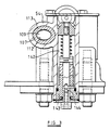
- the lubricant can flow down into the adjuster mechanism as shown in figure 3.
- the housing 54 has a bore 142 which, in relation to Figure 1, extends rearwardly and generally perpendicular to the backplate 22 and contains certain unidentified adjuster components.
- the bore 142 also communicates with the entire interior of the housing 54.
- a plug 143 closes the lower end of the bore and houses a one-way check valve 144 provided at the lower end of the shaft 121 so as to permit the exit of excess lubricant when a predetermined lubricant pressure is attained in the housing 54.
- lubricant can exit the cam shaft portion through the seal 63 ( Figure 2).
- the seal 63 will open at a higher pressure that the one-way check valve 144 so that grease will first exit through the check valve 144.
- any excessively high rate of pressure build-up will cause lubricant to exit also through the seal 63.
- the effective cross-sectional area of the lubricant inlet fitting 141 is substantially less than the relief area provided for by the area of the one-way check valve 144 and the seal 63. As a result, it is ensured that there will not be an undesirable pressure increase in the internal volume of the actuator mechanism during lubrication with normal lubricating equipment.
- a chamber is formed in the actuator 31 by the cover plate 139 and housing 54 and is at least partially filled with a compressible device illustrates as a closed cell foam body 143 which will be compressed upon lubricant introduction.
- a compressible device illustrates as a closed cell foam body 143 which will be compressed upon lubricant introduction.
- the foam body 143 contracts when the effective volume of the actuator housing decreases during tappet retraction and avoids the undesirable expulsion of lubricant from the system, which could occur upon an untoward increase in pressure .
- the lubrication system described enables long-term lubrication to be achieved without the necessity for opening the system and this introduces the possibility for a system which may remain sealed during the expected operational life of the brake.
- foam body may be replaced by other forms of compressible device such a a spring-loaded diaphragm or piston.
- the illustrated camshaft may be replaced by alternative forms of mechanical actuator, such as a wedge device.
Landscapes
- Engineering & Computer Science (AREA)
- General Engineering & Computer Science (AREA)
- Mechanical Engineering (AREA)
- Braking Arrangements (AREA)
- Valves And Accessory Devices For Braking Systems (AREA)
Applications Claiming Priority (2)
| Application Number | Priority Date | Filing Date | Title |
|---|---|---|---|
| US133004 | 1987-12-15 | ||
| US07/133,004 US4813516A (en) | 1987-12-15 | 1987-12-15 | Lubrication system for drum brakes |
Publications (2)
| Publication Number | Publication Date |
|---|---|
| EP0321167A2 true EP0321167A2 (de) | 1989-06-21 |
| EP0321167A3 EP0321167A3 (de) | 1990-01-31 |
Family
ID=22456574
Family Applications (1)
| Application Number | Title | Priority Date | Filing Date |
|---|---|---|---|
| EP88311724A Withdrawn EP0321167A3 (de) | 1987-12-15 | 1988-12-12 | Schmierungssystem für Bremsen |
Country Status (5)
| Country | Link |
|---|---|
| US (1) | US4813516A (de) |
| EP (1) | EP0321167A3 (de) |
| JP (1) | JPH01261522A (de) |
| KR (1) | KR890010440A (de) |
| BR (1) | BR8806602A (de) |
Cited By (1)
| Publication number | Priority date | Publication date | Assignee | Title |
|---|---|---|---|---|
| EP0427426A1 (de) * | 1989-11-04 | 1991-05-15 | Lucas Industries Public Limited Company | Bremsbetätigungsvorrichtung |
Families Citing this family (7)
| Publication number | Priority date | Publication date | Assignee | Title |
|---|---|---|---|---|
| JP2001140952A (ja) * | 1999-11-17 | 2001-05-22 | Heiwa Seiki Kogyo Kk | 雲台の制動機構 |
| US6378658B1 (en) * | 2000-05-10 | 2002-04-30 | Meritor Heavy Vehicle Technology, L.L.C. | Continuous lubricating system |
| US6637553B1 (en) * | 2002-05-29 | 2003-10-28 | Kelelsey-Hayes Company | Mounting stud retention system for use in a vehicle drum-in-hat disc brake assembly |
| US9376098B2 (en) * | 2007-10-31 | 2016-06-28 | Nicholas Eveley | Automotive brake cam assembly |
| US9951833B2 (en) * | 2013-03-04 | 2018-04-24 | Arvinmeritor Technology, Llc | Brake assembly having a brake wing |
| CN108843710B (zh) * | 2018-08-03 | 2020-01-21 | 安徽天裕汽车零部件制造有限公司 | 一种汽车制动凸轮轴 |
| KR102478731B1 (ko) * | 2020-01-23 | 2022-12-20 | 한국기전(주) | 공압식 산업용 브레이크 장치 |
Family Cites Families (12)
| Publication number | Priority date | Publication date | Assignee | Title |
|---|---|---|---|---|
| US1453050A (en) * | 1921-10-28 | 1923-04-24 | Studebaker Corp | Braking mechanism |
| US2064103A (en) * | 1934-11-05 | 1936-12-15 | Vincent H Burdick | Cam assembly for brakes |
| US2826464A (en) * | 1956-05-15 | 1958-03-11 | Sr Elwin A Hawk | Shock proof anti-friction bearing |
| GB796806A (en) * | 1956-08-23 | 1958-06-18 | Gelenkwellenbau Gmbh | Means for lubricating splined couplings between universal joints and propeller shafts |
| DE1208569B (de) * | 1960-04-22 | 1966-01-05 | Perrot Bremse G M B H Deutsche | Fettgeschmierte Bremsnockenwellenlagerung fuer Backenbremsen |
| US3876027A (en) * | 1973-11-21 | 1975-04-08 | George W Crise | Liquid cooled emergency brake for a motor vehicle |
| US4058185A (en) * | 1976-08-09 | 1977-11-15 | Ploeger Kenneth C | Automatic wheel bearing lubricator |
| US4256208A (en) * | 1979-05-29 | 1981-03-17 | Eaton Corporation | Slack adjuster |
| EP0027352B2 (de) * | 1979-10-10 | 1989-11-23 | LUCAS INDUSTRIES public limited company | Automatische Nachstellvorrichtungen für Fahrzeug-Trommel-Backenbremsen |
| EP0098906B1 (de) * | 1982-07-13 | 1986-11-20 | Gaby Eugène Mamery | Betätigungsvorrichtung für Fahrzeugbremsen |
| US4502572A (en) * | 1983-08-31 | 1985-03-05 | Rockwell International Corporation | Disc brake |
| US4720000A (en) * | 1986-07-15 | 1988-01-19 | Raymond Engineering Inc. | Torque wrench with clutches |
-
1987
- 1987-12-15 US US07/133,004 patent/US4813516A/en not_active Expired - Fee Related
-
1988
- 1988-12-12 EP EP88311724A patent/EP0321167A3/de not_active Withdrawn
- 1988-12-14 JP JP63316068A patent/JPH01261522A/ja active Pending
- 1988-12-14 BR BR888806602A patent/BR8806602A/pt unknown
- 1988-12-14 KR KR1019880016640A patent/KR890010440A/ko not_active Abandoned
Cited By (1)
| Publication number | Priority date | Publication date | Assignee | Title |
|---|---|---|---|---|
| EP0427426A1 (de) * | 1989-11-04 | 1991-05-15 | Lucas Industries Public Limited Company | Bremsbetätigungsvorrichtung |
Also Published As
| Publication number | Publication date |
|---|---|
| BR8806602A (pt) | 1989-08-22 |
| US4813516A (en) | 1989-03-21 |
| EP0321167A3 (de) | 1990-01-31 |
| JPH01261522A (ja) | 1989-10-18 |
| KR890010440A (ko) | 1989-08-08 |
Similar Documents
| Publication | Publication Date | Title |
|---|---|---|
| EP1318322B1 (de) | Verbesserungen an Scheibenbremsen | |
| US5601160A (en) | Hydraulically actuated brake assembly for an off-highway implement | |
| CN109281960B (zh) | 盘式制动器 | |
| CN109281961B (zh) | 盘式制动器 | |
| EP0321167A2 (de) | Schmierungssystem für Bremsen | |
| EP1013958B1 (de) | Bremse sowie Betätigungsvorrichtung hierfür | |
| US4014411A (en) | Mechanically actuated disc brake with self adjusting feature | |
| EP0087876B1 (de) | Bremssattel für Scheibenbremsen | |
| US4502572A (en) | Disc brake | |
| EP0139116A1 (de) | Verfahren zum Gestalten eines Bremskolbens für eine Scheibenbremse | |
| CA1230835A (en) | Braking piston for a disc brake | |
| US5819885A (en) | Brake and actuator assembly | |
| EP0137162B1 (de) | Scheibenbremse | |
| US3612225A (en) | Self-adjusting disk parking brake | |
| US4907678A (en) | Air chamber mounting bracket | |
| JPH0640986Y2 (ja) | 車両用デイスクブレ−キ装置 | |
| CA1174612A (en) | Drum brake with combined adjuster and wheel cylinder | |
| US4919239A (en) | Shoe return spring | |
| EP4405595B1 (de) | Gestängestelleranordnung für schwerlastfahrzeuge | |
| US3905456A (en) | Brake assembly | |
| US4266636A (en) | Crown-type caliper brake | |
| JP2554692B2 (ja) | デイスクブレーキの間隙自動調整装置 | |
| KR960010315B1 (ko) | 자동차용 리어 브레이크 장치 | |
| KR0145833B1 (ko) | 브레이크 라이닝 자동 간극조절장치 | |
| JPS58196338A (ja) | 油圧作動式ブレ−キの自動調整装置 |
Legal Events
| Date | Code | Title | Description |
|---|---|---|---|
| PUAI | Public reference made under article 153(3) epc to a published international application that has entered the european phase |
Free format text: ORIGINAL CODE: 0009012 |
|
| AK | Designated contracting states |
Kind code of ref document: A2 Designated state(s): DE GB IT SE |
|
| PUAL | Search report despatched |
Free format text: ORIGINAL CODE: 0009013 |
|
| AK | Designated contracting states |
Kind code of ref document: A3 Designated state(s): DE GB IT SE |
|
| STAA | Information on the status of an ep patent application or granted ep patent |
Free format text: STATUS: THE APPLICATION IS DEEMED TO BE WITHDRAWN |
|
| 18D | Application deemed to be withdrawn |
Effective date: 19900801 |