EP0320876A2 - Fault information collection processing system - Google Patents
Fault information collection processing system Download PDFInfo
- Publication number
- EP0320876A2 EP0320876A2 EP88120804A EP88120804A EP0320876A2 EP 0320876 A2 EP0320876 A2 EP 0320876A2 EP 88120804 A EP88120804 A EP 88120804A EP 88120804 A EP88120804 A EP 88120804A EP 0320876 A2 EP0320876 A2 EP 0320876A2
- Authority
- EP
- European Patent Office
- Prior art keywords
- control unit
- fault information
- unit
- data
- control
- Prior art date
- Legal status (The legal status is an assumption and is not a legal conclusion. Google has not performed a legal analysis and makes no representation as to the accuracy of the status listed.)
- Granted
Links
Images


Classifications
-
- G—PHYSICS
- G06—COMPUTING; CALCULATING OR COUNTING
- G06F—ELECTRIC DIGITAL DATA PROCESSING
- G06F11/00—Error detection; Error correction; Monitoring
- G06F11/07—Responding to the occurrence of a fault, e.g. fault tolerance
- G06F11/0703—Error or fault processing not based on redundancy, i.e. by taking additional measures to deal with the error or fault not making use of redundancy in operation, in hardware, or in data representation
- G06F11/0766—Error or fault reporting or storing
- G06F11/0772—Means for error signaling, e.g. using interrupts, exception flags, dedicated error registers
-
- G—PHYSICS
- G06—COMPUTING; CALCULATING OR COUNTING
- G06F—ELECTRIC DIGITAL DATA PROCESSING
- G06F11/00—Error detection; Error correction; Monitoring
- G06F11/07—Responding to the occurrence of a fault, e.g. fault tolerance
- G06F11/0703—Error or fault processing not based on redundancy, i.e. by taking additional measures to deal with the error or fault not making use of redundancy in operation, in hardware, or in data representation
- G06F11/0706—Error or fault processing not based on redundancy, i.e. by taking additional measures to deal with the error or fault not making use of redundancy in operation, in hardware, or in data representation the processing taking place on a specific hardware platform or in a specific software environment
- G06F11/0745—Error or fault processing not based on redundancy, i.e. by taking additional measures to deal with the error or fault not making use of redundancy in operation, in hardware, or in data representation the processing taking place on a specific hardware platform or in a specific software environment in an input/output transactions management context
Definitions
- the present invention is directed to a fault information collection processing system in a program-stored communication control processing module for controlling data communication between a central processing unit and data communication lines on the basis of appropriate communication control programs.
- Fig. 1 illustrates a block diagram showing the configuration of an example of this type of electronic computer network.
- the symbols 1a through 1c designate a plurality of central processing units for performing the arithmetic and control operations required for data processing.
- Communication control processing units respectively indicated at 2a, 2b and 2c are connected to central processing unit 1a, 1b and 1c.
- the symbols 3a to 3cr epresent input/output channels through which central processing units 1a to 1c are connected to communication control processing units 2a through 2c.
- Data communication lines 2a, 2b and 2c serve to connect communication control processing units 2a through 2c to each other.
- Terminal units 5a, 5b and 5c are connected via terminal data communication lines 6a, 6b and 6c to communication control processing units 2a through 2c.
- Fig. 2 is a block diagram depicting the internal configuration of each of the communication control units 2a to 2c depicted in Fig. 1.
- reference numeral 2 denotes a communication control module, and 3 designates an input/output channel for connecting central processing unit 1 to communication control unit 2.
- Communication control module 2 functions to control input/output channel 3 so as to cause them to transfer the data between central processing unit 1 and the module 2 itself.
- communication control module 2 is composed of: a channel control unit 7 for controlling data transfer between input/output channel 3 and communication control processing module 2; a storage unit 8 for storing a communication control program 9 and the data transferred to data communication lines 4 and 6; a line control unit 11 for controlling the data transfer between data communication lines 4 and 6; and a central control unit 10 which executes communication control program 9 for the purpose of controlling channel control unit 7, storage unit 8 and line control unit 11.
- the program of the central processing unit 1 depicted in Fig. 2 involves the preparation of a piece of destination information for the communication as well as a communication statement, and the data are thereby transferred and received by way of input/output channel 3 between communication control processing module 2 and central processing unit 1.
- the particular processing associated with the subsequent data communication is executed on the basis of communication control program 9 in communication control processing module 2.
- Such processing is, as a matter of fact, executed by central control unit 10 which sequentially reads commands from communication control program 9 stored in storage unit 8.
- the communication destination address and communication statement transmitted via input/output channel 3 are temporarily loaded through channel control unit 7 into storage unit 8 under the control of central control unit 10. Subsequently, the communication destination address is decrypted under the control of communication control program 9, and the communication statement to which transmission control characters pursuant to individual communication rules are added is transferred to line control unit 11 in transmission control procedures that are preset in the communication statement for each communication line. After a parallel/series conversion of data has been effected in line control unit 11, the data on the communication statement including the transmission control characters are sent to data communication lines 4 and 6.
- central processing unit 1 In the receipt of data by central processing unit 1 from data communication lines 4 and 6, data containing the transmission control characters transmitted from data communication lines 4 and 6 undergo series/parallel conversion in line control unit 11. The thus converted data are then organized into a communication statement and destination information by deleting the transmission control characters under the control of communication control program 9, thereby loading such statement and information into storage unit 8. Thereafter, central control unit 11 transmits to the central processing unit 1 only the communication statement and destination information via channel control unit 7 and via input/output channel 3. It follows that, by virtue of the role played by communication control processing module 2, the central processing unit 1 is set free from such processes as identification of complicated transfer destinations and addition or deletion of control characters pursuant to the respective communication rules.
- the prior art communication control processing module is, however, arranged such that the individual component devices are, as illustrated in Fig. 2, radially disposed about central control unit 10 on which the control functions of decrypting and executing communication control program 9 are concentrated.
- central control unit 10 itself has to control the collection of pieces of information on each fault that occurs. It is therefore difficult to collect detailed information.
- channel control unit 7 organizes the fault information gathered by central control unit 10 into information of several bytes.
- the thus organized information of several bytes is merely transferred as a hardware function of channel control unit 7 to central processing unit 1 in the form of channel-state information concomitant to the input/output operations associated with central processing unit 1.
- the fault information is inadequate in terms of both quality and quantity.
- a fault information collection processing system characterized in that: a service control unit 32 for effecting control over the collection processing of fault information serves to gather pieces of fault information and identify the component devices in which faults have occurred in any component device of a communication control processing module 22; the fault information is loaded in a predetermined storage region (an expanded log-out region 43) of a storage unit 8; and thereafter the stored fault information is transferred via channel control unit 7 to a central processing unit 1, thus performing the collection-processing of the fault information.
- a service control unit 32 for effecting control over the collection processing of fault information serves to gather pieces of fault information and identify the component devices in which faults have occurred in any component device of a communication control processing module 22; the fault information is loaded in a predetermined storage region (an expanded log-out region 43) of a storage unit 8; and thereafter the stored fault information is transferred via channel control unit 7 to a central processing unit 1, thus performing the collection-processing of the fault information.
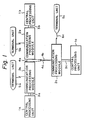
- FIG. 3(A) this is a block diagram of the constitution of a communication control processing module in which a fault information collection processing system representing one embodiment of the present invention is utilized. Components in Fig. 3(A) that correspond to those depicted in Fig. 1 are given the same symbols, and the related description is therefore omitted here.
- the numeral 32 designates a service control unit which is incorporated in a communication control processing module 22 and is adapted to effect control over collection-processing of fault information.
- An appropriate maintenance console generally indicated at 33 is connected to service control unit 32. Note that this console 33 is not necessarily connected to service control unit 32.
- the numeral 34 represents a common data bus through which a storage unit 8, a central control unit 10, a channel control unit 7, a line control unit 11 and service control unit 32 are connected.
- the numeral 35 denotes a signal line via which a group of operation control signals for controlling operational conditions are transmitted from service control unit 32 to storage unit 8, central control unit 10, channel control unit 7 and line control unit 11.
- Fig. 4 is a block diagram illustrating storage regions of storage unit 8 when detailed fault information in communication control processing module 22 is being transferred to central processing unit 1.
- the numeral 41 stands for a communication control program storage region; 42 a buffer region for data transferred and received between data communication lines 4 and 6; 43 an expanded log-out region for temporarily storing detailed fault information; and 44 a transfer program storage region for transferring the data stored in expanded log-out region 43 via channel control unit 7 as well as via input/output channel 3 to central processing unit 1.
- central processing unit 10 sequentially reads commands from a communication control program 9 loaded in a communication control/program storage region of storage unit 8 by way of common data bus 34, and performs processing in conformity with command instructions.
- central control unit 10 executes a command to read in, via common data bus 34, the data transferred from central processing unit 1 through input/output channel 3 and channel control unit 7, and subsequently a command to store the thus read data in buffer region 42 of storage unit 8 through common data bus 34.
- central control unit 10 decrypts a communication statement and the destination of the data stored in buffer region 42 pursuant to the instructions given by communication control program 9, and executes the command to transfer the data via common data bus 34 to line control unit 11 after adding, to the communication statement, transfer control characters based on communication rules in accordance with attributes of the predetermined data communication lines.
- the line control unit 11 sends out the received data to data communication lines 4 and 6 after effecting parallel/series conversion on such data.
- central control unit 10 performs processes reverse to the above-mentioned ones in conformity with the instructions of communication control program 9 in the case of transmitting data to central processing unit 1 after receiving data from data line communication lines 4 and 6. The transfer and receipt of the data are thus carried out between central processing unit 1 and data communication lines 4 and 6 through communication control processing module 22.
- service control unit 32 constantly monitors the presence or non-presence of any abnormality in the component devices incorporated in communication control processing module 22.
- the component device in which the abnormality has been found out serves to inform service control unit 32 of the occurrence of an abnormal condition via signal line 35.
- Service control unit 32 informed of the abnormality in the component device of the communication control processing module through signal line 35, in turn performs control to temporarily freeze the operation of the component device of the communication control processing module through signal line 35, and then collects pieces of detailed fault information specifying the component devices experiencing the faults in question, classifying these faults and indicating their severity through common data bus 34.
- An internal storage region of service control unit 32 temporality stores the detailed fault information which will thereafter be loaded in expanded log-out region 43 of storage unit 8 via common data bus 34.
- the method of identifying the fault information involves the steps of disposing detectors D in predetermined positions of the respective component devices and detecting the fact that signals of given magnitude have been output from given detectors D on the side of service control unit 32.
- Detector D may probably include a temperature detector, voltage detector and current detector, or a program-runaway detector.
- reference to the fault information temporarily stored in service control unit 32 can be made by means of maintenance console 33 connected to service control unit 32.
- Service control unit 32 generates signals designated to initialize certain functions of the individual component devices via signal line 35 and makes preparations for resuming the operation of communication control processing module 22.
- a command execution initiating address in central control unit 10 is set to the top of a transfer program storage region 44 of storage unit 8, and control is performed to allow a fault information transfer program to be executed instead of communication control program 9 when the operation is resumed, and thereafter central control unit 10 is actuated.
- central control unit 10 functions to coincide with the operation wherein communication control program 9 during the normal operation serves to transfer the data of buffer region 42 via channel control unit 7 and also input/output channel 3 to central processing unit 1.
- Central control unit 10 then transfers all the detailed fault information of expanded log-out region 43 to central processing unit 1.
- central processing unit 1 is capable of identifying and fixing the faulty device in communication with control processing module 22 on the basis of the detailed fault information, and is also able to output easy-to-observe detailed fault information for maintenance staff in accordance with an edit program of central processing unit 1.
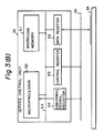
- Fig. 3(B) is a block diagram depicting the internal configuration of the service control unit 32 illustrated in Fig. 3(A).
- reference numeral 50 designates a microprocessor; 51 a microcode memory adapted to store a microcode for controlling microprocessor 50; 52 a data register used for transferring data between microprocessor 50 and common data bus 34; 53 a control register for transferring and receiving signals between signal line 35 and the control register itself in order to control the operation of the communication control processing module as a whole; and 54 a data bus for connecting microprocessor 50, microcode memory 51, data register 52 and control register 53.
- the numeral 55 represents an abnormal signal register for holding abnormal signals from the component devices of the communication control processing module. Abnormal signal register 55 imparts an interruption request to microprocesssor 50 if any abnormal condition occurs in the component device.
- Fig. 3(C) is a block diagram illustrating the internal configuration of the storage unit 8 depicted in Fig. 3(A).
- numeral 60 denotes a memory array for storing a communication control program or a transfer program; 61 a memory data register for transferring and receiving memory write-read data between common data bus 34 and memory array 60; 62 a memory address register for assigning, to memory array 60, an address for writing and reading the memory data; and 63 a memory write/read control circuit for performing control to write the data of memory data register 61 into memory array 60 in accordance with the address indicated by memory address register 62 on receiving an instruction through common data bus 34, and to read the data from the address of memory array 60, which is indicated by memory address register 62, into memory data register 61.
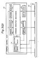
- Fig. 3(D) is a block diagram showing the internal configuration of the central control unit 10 shown in Fig. 3(A).
- numeral 70 denotes a command register for reading and holding a command from the communication control program of the transfer program stored in storage unit 8; 71 an operand register for reading and holding data which is employed for the communication control program or the transfer program stored in storage unit 8 from common data bus 34; 72 a command execution mechanism for processing the data in operand register 71 in conformity with a command code from command register 70; 73 a command address register for holding the memory address of the next command to be executed; 74 a data register used for transmitting the data obtained as a result of executing the command to common data bus 34; and 75 a common execution mechanism control circuit for controlling the start/stop of the command execution mechanism control circuit on the basis of an instruction given by service control unit 32.
- line control unit 11 If the abnormality appears in, e.g., line control unit 11 which is regarded as a component device of comminication control processing module 22, line control unit 11 transmits an abnormality information signal to signal line 35.
- the abnormality information signal is then held by abnormal signal register 55 incorporated in service control unit 32, and an interruption takes place in microprocessor 50.
- Microprocessor 50 initiates the execution of an interruption processing microcode stored in a predetermined region of microcode memory 51. Based on the interruption processing microcode, microprocessor 50 sets a control signal in control register 53 for stopping central control unit 10 by way of data bus 54.
- the stop control signal is transmitted via common data bus 35 to command execution mechanism control circuit 75, thereby stopping the function of command execution mechanism 72 preparatory to halting execution of communication control program 9.
- microprocessor 50 sets request signals for imparting information on the internal conditions of the individual component devices of communication control processing module 22 to control register 53 via data bus 54.
- Microprocessor 50 also performs a function of sequentially writing information sent from the respective devices into microcode memory 51 via data register 52 and data bus 54.
- the method adapted for selecting the devices at that time may be based on a step wherein microprocessor 50 transmits the signal for selecting each individual device to signal line 35 through control register 53, or alternatively on a step wherein pieces of information are sequentially fetched by sending addresses assigned to the respective devices to common data bus 34 through data register 52.
- Microprocessor 50 takes all the information on the internal conditions of the respective devices for storage in microcode memory 51, and thereafter transfers the thus obtained information to storage unit 8. Firstly, the top address of expanded log-out region 43 of storage unit 8 is set in data register 52 via data bus 54. Secondly, the top address is transmitted to common data bus 34. A control signal transferred to and written into memory address register 62 is set via data bus 54 into control register 53. Upon transmission of the write signal of memory address register 62 through signal line 35, storage unit 8 takes the top address out of expanded log-out region 43, which is sent to common data bus 34, and supplies the same to memory address register 62 under control of write/read control circuit 63.
- Microprocessor 50 subsequently reads the content of microcode memory 51 and sets the initial data of the intra-device condition information in data register 52 through data bus 54.
- the control signal transferred to and written into memory data resister 61 of storage unit 8 through common data bus 34 is set in control register 53 via data bus 54.
- Storage unit 8 takes the intra-device condition information present on common data bus 34 into memory data register 61 under control of write/read control circuit 63 upon transmitting the write signal of memory data register 61 via signal line 35.
- Microprocessor 50 further sets the write control signal of storage unit 8 in data register 52 by way of data bus 54, while storage unit 8 writes the content of memory data register 61 into the address specified by memory address register 62 immediately the memory write signal is transmitted via signal line 35.
- Microprocessor 50 advances by one step a value which is to be set in memory address register 62 and reads the next intra-device condition information from microcode memory 51. The operations discussed above are repeated till transfer of all the intra-device condition information has been completed. After transferring all the condition information which has been obtained from the respective component devices incorporated in communication control processing module 22 to expanded log-out region 43 of storage unit 8, microprocessor 50 transmits reset signals for initializing the above-mentioned component devices via data bus 54 to control register 53.
- Microprocessor 50 sets an initiation address of transfer program storage region 44 of storage unit 8 in data register 52 by way of data bus 54.
- a control signal for transferring to and writing the initiation address into operand register 71 of central control unit 10 via common data bus 34 is set in control register 53 via data bus 54.
- Central control unit 10 operates to take the transfer program initiation address existing on common data bus 34 into operand register 71 under the control of command execution mechanism control circuit 75 upon transmitting the write signal of operand register 71 via signal line 35.
- Microprocessor 50 further sets a control signal for transferring the content of operand register 71 of central control unit 10 to command address register 73 in data register 52 via date bus 54.
- central control unit 10 Upon transmission of the control signal via signal line 35, central control unit 10 transfers the content of operand register 71 to command address register 73 under control of command execution mechanism control circuit 75. Thereafter, microprocessor 50 functions to set an operation resuming signal of central control unit 10 in control register 53 by way of data bus 54. Immediately after the operation resuming signal has been transmitted via signal line 35, central control unit 10 reads a transfer program command from storage unit 8 pursuant to the address assigned to command address register 73, and initiates the execution thereof.
- the description of the transfer program is associated with the commands of central control unit 10.
- Central control unit 10 sequentially reads the commands to command register 70 through common data bus 34 in conformity with the commands, thereby performing the command.
- the intra-device condition information stored in expanded log-out region 43 in accordance with the processing of the transfer program is read into operand register 71 via common data bus 34.
- the intra-device condition information is then set through command execution mechanism 72 in data register 74.
- the intra-device condition information of data register 74 is transferred via common data bus 34 to channel control unit 7, and is then, as in the case of the data transfer of communication control program 9, sent via input/output channel 23 to central processing unit 1.
- a branching command is executed pursuant to the transfer program whereby predetermined initiation address of communication control program storage region 41 is set in command address register 73, thereby reverting to the normal processing of the communication control program.
- the component devices of the communication control processing module include an appropriate service control unit similar to a service processing unit typically added to a sophisticated central processing unit. Whenever a fault occurs in a component device and it is thereby impossible to continue the processing of the communication control program, the service control unit collects pieces of fault information in place of the central control unit and transfers the detailed fault information to the central processing unit. This provides the following benefits. It is feasible to gather pieces of fault information pertaining to a plurality of communication control processing modules in the central processing unit.
- the central processing unit is capable of identifying and fixing the faulty device without the burden of needing to gain access to the positions where the respective communication control processing modules are installed.
- detailed fault information can be output in an easy-to-observe form for maintenance staff in accordance with the edit program of the central processing unit. Thanks to the availability of accurate system fault information, the time needed for restitution can be reduced, and the operability during preventive maintenance is improved.
Abstract
Description
- The present invention is directed to a fault information collection processing system in a program-stored communication control processing module for controlling data communication between a central processing unit and data communication lines on the basis of appropriate communication control programs.
- One typical arrangement of a large scale electronic computer network in the field of sophisticated electronic computer systems involves intricate combinations of a plurality of central processing units and a multiplicity of data communication lines with decentralized processing pervading. In this type of electronic computer network, it is a widespread practice for the communication control processing module, which stores an appropriate communication control program and functions independently of the central processing unit, to be connected to an input/output channel so that there is no drop in the processing capability of the central processing unit in controlling the data communication lines, which requires a variety of transmission control procedures.
- Fig. 1 illustrates a block diagram showing the configuration of an example of this type of electronic computer network. In Fig. 1, the
symbols 1a through 1c designate a plurality of central processing units for performing the arithmetic and control operations required for data processing. Communication control processing units respectively indicated at 2a, 2b and 2c are connected tocentral processing unit 1a, 1b and 1c. The symbols 3a to 3cr epresent input/output channels through whichcentral processing units 1a to 1c are connected to communicationcontrol processing units 2a through 2c.Data communication lines control processing units 2a through 2c to each other.Terminal units data communication lines 6a, 6b and 6c to communicationcontrol processing units 2a through 2c. - Fig. 2 is a block diagram depicting the internal configuration of each of the
communication control units 2a to 2c depicted in Fig. 1. Referring to Fig. 2,reference numeral 2 denotes a communication control module, and 3 designates an input/output channel for connectingcentral processing unit 1 tocommunication control unit 2.Communication control module 2 functions to control input/output channel 3 so as to cause them to transfer the data betweencentral processing unit 1 and themodule 2 itself. To be more specific,communication control module 2 is composed of: achannel control unit 7 for controlling data transfer between input/output channel 3 and communicationcontrol processing module 2; astorage unit 8 for storing acommunication control program 9 and the data transferred todata communication lines data communication lines central control unit 10 which executescommunication control program 9 for the purpose of controllingchannel control unit 7,storage unit 8 and line control unit 11. - We will next deal with the function of the program-stored communication control processing module. In the case of effecting data communication by use of the electronic computer defined as a destination station for the communication, the program of the
central processing unit 1 depicted in Fig. 2 involves the preparation of a piece of destination information for the communication as well as a communication statement, and the data are thereby transferred and received by way of input/output channel 3 between communicationcontrol processing module 2 andcentral processing unit 1. The particular processing associated with the subsequent data communication is executed on the basis ofcommunication control program 9 in communicationcontrol processing module 2. Such processing is, as a matter of fact, executed bycentral control unit 10 which sequentially reads commands fromcommunication control program 9 stored instorage unit 8. - On the occasion of a data transmission from
central processing unit 1 todata communication lines output channel 3 are temporarily loaded throughchannel control unit 7 intostorage unit 8 under the control ofcentral control unit 10. Subsequently, the communication destination address is decrypted under the control ofcommunication control program 9, and the communication statement to which transmission control characters pursuant to individual communication rules are added is transferred to line control unit 11 in transmission control procedures that are preset in the communication statement for each communication line. After a parallel/series conversion of data has been effected in line control unit 11, the data on the communication statement including the transmission control characters are sent todata communication lines - In the receipt of data by
central processing unit 1 fromdata communication lines data communication lines communication control program 9, thereby loading such statement and information intostorage unit 8. Thereafter, central control unit 11 transmits to thecentral processing unit 1 only the communication statement and destination information viachannel control unit 7 and via input/output channel 3. It follows that, by virtue of the role played by communicationcontrol processing module 2, thecentral processing unit 1 is set free from such processes as identification of complicated transfer destinations and addition or deletion of control characters pursuant to the respective communication rules. - The prior art communication control processing module is, however, arranged such that the individual component devices are, as illustrated in Fig. 2, radially disposed about
central control unit 10 on which the control functions of decrypting and executingcommunication control program 9 are concentrated. Hence, in a conventional fault information collection processing system in which certain faults occur in components of the hardware,central control unit 10 itself has to control the collection of pieces of information on each fault that occurs. It is therefore difficult to collect detailed information. On the other hand, before transferring the fault information tocentral processing unit 1,channel control unit 7 organizes the fault information gathered bycentral control unit 10 into information of several bytes. The thus organized information of several bytes is merely transferred as a hardware function ofchannel control unit 7 tocentral processing unit 1 in the form of channel-state information concomitant to the input/output operations associated withcentral processing unit 1. The fault information is inadequate in terms of both quality and quantity. - Speaking of the various sorts of computer systems which have been proposed of late, construction of a complicated electronic computer network involves a step of combining, as depicted in Fig. 1, a plurality of
central processing units 1a, 1b and 1c with a plurality of comminicationcontrol processing units central processing units 1a through 1c pieces of fault information relative to individual devices that combine to form a computer system and systemmatically arranging such information into easy- to-observe system fault information for use by maintenance staff. The conventional fault information collection processing system involves certain inherent problems, however, since the information transferred from communicationcontrol processing modules central processing units 1a, 1b and 1c is insufficient, and it is impossible to create accurate system fault information incentral processing units 1a through 1c. Thus the above-described need has not been satisfactorily met. - It is a primary object of the present invention to obviate the foregoing problems and to provide a fault information collection processing system capable of facilitating maintenance and of allowing any faults that occur in component devices incorporated in a communication control processing module to be readily identified by a step wherein a central processing unit systematically arranges fault information into easy-to-observe system fault information for use by maintenance staff as well as transferring the detailed fault information to the central processing unit.
- To this end, according to one aspect of the invention, there is provided a fault information collection processing system characterized in that: a
service control unit 32 for effecting control over the collection processing of fault information serves to gather pieces of fault information and identify the component devices in which faults have occurred in any component device of a communicationcontrol processing module 22; the fault information is loaded in a predetermined storage region (an expanded log-out region 43) of astorage unit 8; and thereafter the stored fault information is transferred viachannel control unit 7 to acentral processing unit 1, thus performing the collection-processing of the fault information. - Other objects and advantages of the invention will become apparent from the ensuring discussion in conjunction with the accompanying drawings, in which:
- Fig. 1 is a block diagram illustrating the configuration of an electronic computer network in an example of the prior art;
- Fig. 2 is a block diagram depicting the configuration of a communication control processing module in which a conventional fault information collection processing system is utilized;
- Fig. 3(A) is a block diagram depicting the constitution of a communication control processing module employing a fault information collection processing system representing one embodiment of the present invention; Fig. 3(B) is a block diagram depicting the internal constitution of one of the units shown in Fig. 3(A); Fig. 3(C) is a block diagram showing the internal constitution of one of the units illustrated in Fig. 3(A); Fig. 3(D) is a block diagram depicting the internal constitution of the central control unit shown in Fig. 3(A); and
- Fig. 4 is a diagram illustrating storage regions of the storage unit shown in Fig. 3(C).
- Referring first to Fig. 3(A), this is a block diagram of the constitution of a communication control processing module in which a fault information collection processing system representing one embodiment of the present invention is utilized. Components in Fig. 3(A) that correspond to those depicted in Fig. 1 are given the same symbols, and the related description is therefore omitted here. Referring again to Fig. 3(A), the
numeral 32 designates a service control unit which is incorporated in a communicationcontrol processing module 22 and is adapted to effect control over collection-processing of fault information. An appropriate maintenance console generally indicated at 33 is connected toservice control unit 32. Note that thisconsole 33 is not necessarily connected toservice control unit 32. Thenumeral 34 represents a common data bus through which astorage unit 8, acentral control unit 10, achannel control unit 7, a line control unit 11 andservice control unit 32 are connected. Thenumeral 35 denotes a signal line via which a group of operation control signals for controlling operational conditions are transmitted fromservice control unit 32 tostorage unit 8,central control unit 10,channel control unit 7 and line control unit 11. - Fig. 4 is a block diagram illustrating storage regions of
storage unit 8 when detailed fault information in communicationcontrol processing module 22 is being transferred tocentral processing unit 1. In Fig. 4, thenumeral 41 stands for a communication control program storage region; 42 a buffer region for data transferred and received betweendata communication lines region 43 viachannel control unit 7 as well as via input/output channel 3 tocentral processing unit 1. - The next part of the description will be focussed on the function of this embodiment. During normal operation,
central processing unit 10 sequentially reads commands from acommunication control program 9 loaded in a communication control/program storage region ofstorage unit 8 by way ofcommon data bus 34, and performs processing in conformity with command instructions. When data is sent fromcentral processing unit 1 to a variety ofdata communication lines central control unit 10 executes a command to read in, viacommon data bus 34, the data transferred fromcentral processing unit 1 through input/output channel 3 andchannel control unit 7, and subsequently a command to store the thus read data inbuffer region 42 ofstorage unit 8 throughcommon data bus 34. In the second place,central control unit 10 decrypts a communication statement and the destination of the data stored inbuffer region 42 pursuant to the instructions given bycommunication control program 9, and executes the command to transfer the data viacommon data bus 34 to line control unit 11 after adding, to the communication statement, transfer control characters based on communication rules in accordance with attributes of the predetermined data communication lines. The line control unit 11 sends out the received data todata communication lines - In communication
control processing module 22,central control unit 10 performs processes reverse to the above-mentioned ones in conformity with the instructions ofcommunication control program 9 in the case of transmitting data tocentral processing unit 1 after receiving data from dataline communication lines central processing unit 1 anddata communication lines control processing module 22. Meanwhile,service control unit 32 constantly monitors the presence or non-presence of any abnormality in the component devices incorporated in communicationcontrol processing module 22. - If an abnormal condition is present in any of the component devices of communication
control processing module 22, the component device in which the abnormality has been found out serves to informservice control unit 32 of the occurrence of an abnormal condition viasignal line 35.Service control unit 32, informed of the abnormality in the component device of the communication control processing module throughsignal line 35, in turn performs control to temporarily freeze the operation of the component device of the communication control processing module throughsignal line 35, and then collects pieces of detailed fault information specifying the component devices experiencing the faults in question, classifying these faults and indicating their severity throughcommon data bus 34. An internal storage region ofservice control unit 32 temporality stores the detailed fault information which will thereafter be loaded in expanded log-outregion 43 ofstorage unit 8 viacommon data bus 34. In this case, the method of identifying the fault information involves the steps of disposing detectors D in predetermined positions of the respective component devices and detecting the fact that signals of given magnitude have been output from given detectors D on the side ofservice control unit 32. Detector D may probably include a temperature detector, voltage detector and current detector, or a program-runaway detector. In this instance, reference to the fault information temporarily stored inservice control unit 32 can be made by means ofmaintenance console 33 connected toservice control unit 32. -
Service control unit 32 generates signals designated to initialize certain functions of the individual component devices viasignal line 35 and makes preparations for resuming the operation of communicationcontrol processing module 22. At this moment, a command execution initiating address incentral control unit 10 is set to the top of a transferprogram storage region 44 ofstorage unit 8, and control is performed to allow a fault information transfer program to be executed instead ofcommunication control program 9 when the operation is resumed, and thereaftercentral control unit 10 is actuated. In the wake of this step and pursuant to the instruction of the fault information transfer program stored instorage unit 8,central control unit 10 functions to coincide with the operation whereincommunication control program 9 during the normal operation serves to transfer the data ofbuffer region 42 viachannel control unit 7 and also input/output channel 3 tocentral processing unit 1.Central control unit 10 then transfers all the detailed fault information of expanded log-outregion 43 tocentral processing unit 1. Hence,central processing unit 1 is capable of identifying and fixing the faulty device in communication withcontrol processing module 22 on the basis of the detailed fault information, and is also able to output easy-to-observe detailed fault information for maintenance staff in accordance with an edit program ofcentral processing unit 1. - Fig. 3(B) is a block diagram depicting the internal configuration of the
service control unit 32 illustrated in Fig. 3(A). In thisfigure reference numeral 50 designates a microprocessor; 51 a microcode memory adapted to store a microcode for controllingmicroprocessor 50; 52 a data register used for transferring data betweenmicroprocessor 50 andcommon data bus 34; 53 a control register for transferring and receiving signals betweensignal line 35 and the control register itself in order to control the operation of the communication control processing module as a whole; and 54 a data bus for connectingmicroprocessor 50,microcode memory 51, data register 52 andcontrol register 53. The numeral 55 represents an abnormal signal register for holding abnormal signals from the component devices of the communication control processing module.Abnormal signal register 55 imparts an interruption request tomicroprocesssor 50 if any abnormal condition occurs in the component device. - Fig. 3(C) is a block diagram illustrating the internal configuration of the
storage unit 8 depicted in Fig. 3(A). In Fig. 3(C) numeral 60 denotes a memory array for storing a communication control program or a transfer program; 61 a memory data register for transferring and receiving memory write-read data betweencommon data bus 34 andmemory array 60; 62 a memory address register for assigning, tomemory array 60, an address for writing and reading the memory data; and 63 a memory write/read control circuit for performing control to write the data of memory data register 61 intomemory array 60 in accordance with the address indicated bymemory address register 62 on receiving an instruction throughcommon data bus 34, and to read the data from the address ofmemory array 60, which is indicated bymemory address register 62, into memory data register 61. - Fig. 3(D) is a block diagram showing the internal configuration of the
central control unit 10 shown in Fig. 3(A). In thisfigure numeral 70 denotes a command register for reading and holding a command from the communication control program of the transfer program stored instorage unit 8; 71 an operand register for reading and holding data which is employed for the communication control program or the transfer program stored instorage unit 8 fromcommon data bus 34; 72 a command execution mechanism for processing the data in operand register 71 in conformity with a command code fromcommand register 70; 73 a command address register for holding the memory address of the next command to be executed; 74 a data register used for transmitting the data obtained as a result of executing the command tocommon data bus 34; and 75 a common execution mechanism control circuit for controlling the start/stop of the command execution mechanism control circuit on the basis of an instruction given byservice control unit 32. - The discussion now be focussed, in conjunction with Figs. 3(A) through 3(D) and Fig. 4, on the detailed operations conducted in situations where an abnormal condition is present in communication
control processing module 22; the processing of the communication control program is halted; and the fault information is transferred viachannel control unit 7 and input/output channel 3 tocentral processing unit 1 in accordance with the transfer program. - If the abnormality appears in, e.g., line control unit 11 which is regarded as a component device of comminication
control processing module 22, line control unit 11 transmits an abnormality information signal to signalline 35. The abnormality information signal is then held byabnormal signal register 55 incorporated inservice control unit 32, and an interruption takes place inmicroprocessor 50.Microprocessor 50 initiates the execution of an interruption processing microcode stored in a predetermined region ofmicrocode memory 51. Based on the interruption processing microcode,microprocessor 50 sets a control signal in control register 53 for stoppingcentral control unit 10 by way ofdata bus 54. The stop control signal is transmitted viacommon data bus 35 to command executionmechanism control circuit 75, thereby stopping the function of command execution mechanism 72 preparatory to halting execution ofcommunication control program 9. Subsequent to this step,microprocessor 50 sets request signals for imparting information on the internal conditions of the individual component devices of communicationcontrol processing module 22 to controlregister 53 viadata bus 54.Microprocessor 50 also performs a function of sequentially writing information sent from the respective devices intomicrocode memory 51 via data register 52 anddata bus 54. The method adapted for selecting the devices at that time may be based on a step whereinmicroprocessor 50 transmits the signal for selecting each individual device to signalline 35 throughcontrol register 53, or alternatively on a step wherein pieces of information are sequentially fetched by sending addresses assigned to the respective devices tocommon data bus 34 through data register 52. -
Microprocessor 50 takes all the information on the internal conditions of the respective devices for storage inmicrocode memory 51, and thereafter transfers the thus obtained information tostorage unit 8. Firstly, the top address of expanded log-outregion 43 ofstorage unit 8 is set in data register 52 viadata bus 54. Secondly, the top address is transmitted tocommon data bus 34. A control signal transferred to and written intomemory address register 62 is set viadata bus 54 intocontrol register 53. Upon transmission of the write signal ofmemory address register 62 throughsignal line 35,storage unit 8 takes the top address out of expanded log-outregion 43, which is sent tocommon data bus 34, and supplies the same tomemory address register 62 under control of write/read control circuit 63. -
Microprocessor 50 subsequently reads the content ofmicrocode memory 51 and sets the initial data of the intra-device condition information in data register 52 throughdata bus 54. The control signal transferred to and written intomemory data resister 61 ofstorage unit 8 throughcommon data bus 34 is set in control register 53 viadata bus 54.Storage unit 8 takes the intra-device condition information present oncommon data bus 34 into memory data register 61 under control of write/read control circuit 63 upon transmitting the write signal of memory data register 61 viasignal line 35.Microprocessor 50 further sets the write control signal ofstorage unit 8 in data register 52 by way ofdata bus 54, whilestorage unit 8 writes the content of memory data register 61 into the address specified bymemory address register 62 immediately the memory write signal is transmitted viasignal line 35.Microprocessor 50 advances by one step a value which is to be set inmemory address register 62 and reads the next intra-device condition information frommicrocode memory 51. The operations discussed above are repeated till transfer of all the intra-device condition information has been completed. After transferring all the condition information which has been obtained from the respective component devices incorporated in communicationcontrol processing module 22 to expanded log-outregion 43 ofstorage unit 8,microprocessor 50 transmits reset signals for initializing the above-mentioned component devices viadata bus 54 to controlregister 53. -
Microprocessor 50 then sets an initiation address of transferprogram storage region 44 ofstorage unit 8 in data register 52 by way ofdata bus 54. A control signal for transferring to and writing the initiation address into operand register 71 ofcentral control unit 10 viacommon data bus 34 is set in control register 53 viadata bus 54.Central control unit 10 operates to take the transfer program initiation address existing oncommon data bus 34 into operand register 71 under the control of command executionmechanism control circuit 75 upon transmitting the write signal of operand register 71 viasignal line 35.Microprocessor 50 further sets a control signal for transferring the content of operand register 71 ofcentral control unit 10 to commandaddress register 73 in data register 52 viadate bus 54. Upon transmission of the control signal viasignal line 35,central control unit 10 transfers the content of operand register 71 tocommand address register 73 under control of command executionmechanism control circuit 75. Thereafter,microprocessor 50 functions to set an operation resuming signal ofcentral control unit 10 in control register 53 by way ofdata bus 54. Immediately after the operation resuming signal has been transmitted viasignal line 35,central control unit 10 reads a transfer program command fromstorage unit 8 pursuant to the address assigned tocommand address register 73, and initiates the execution thereof. - As in the case of
communication control program 9, the description of the transfer program is associated with the commands ofcentral control unit 10.Central control unit 10 sequentially reads the commands to commandregister 70 throughcommon data bus 34 in conformity with the commands, thereby performing the command. The intra-device condition information stored in expanded log-outregion 43 in accordance with the processing of the transfer program is read into operand register 71 viacommon data bus 34. The intra-device condition information is then set through command execution mechanism 72 in data register 74. The intra-device condition information of data register 74 is transferred viacommon data bus 34 tochannel control unit 7, and is then, as in the case of the data transfer ofcommunication control program 9, sent via input/output channel 23 tocentral processing unit 1. After the transfer of all the intra-device condition information has been finished, a branching command is executed pursuant to the transfer program whereby predetermined initiation address of communication controlprogram storage region 41 is set incommand address register 73, thereby reverting to the normal processing of the communication control program. - In accordance with the embodiment discussed above, the component devices of the communication control processing module include an appropriate service control unit similar to a service processing unit typically added to a sophisticated central processing unit. Whenever a fault occurs in a component device and it is thereby impossible to continue the processing of the communication control program, the service control unit collects pieces of fault information in place of the central control unit and transfers the detailed fault information to the central processing unit. This provides the following benefits. It is feasible to gather pieces of fault information pertaining to a plurality of communication control processing modules in the central processing unit. Even in a case where a fault is produced in just one of the plurality of communication control processing modules, the central processing unit is capable of identifying and fixing the faulty device without the burden of needing to gain access to the positions where the respective communication control processing modules are installed. In addition, detailed fault information can be output in an easy-to-observe form for maintenance staff in accordance with the edit program of the central processing unit. Thanks to the availability of accurate system fault information, the time needed for restitution can be reduced, and the operability during preventive maintenance is improved.
- Although the illustrated embodiment of the present invention has been described in great detail with reference to the accompanying drawings, it is to be understood that the invention is not limited to this precise embodiment. Various changes or modifications may be effected by one skilled in the art without departing from the scope or spirit of the invention.
- The invention will be understood more readily with reference to the following examples; however these examples are intended to illustrate the invention and are not to be construed to limit the scope of the invention.
Claims (4)
a channel control unit for controlling the transfer of data between an input/output channel and said central processing unit for performing arithmetic and control operations required for data processing;
a storage unit for storing a communication control program;
a line control unit for controlling data communication lines;
a central control unit for controlling said channel control unit, said storage unit and said line control unit on the basis of said communication control program; and
a service control unit for controlling collection-processing of fault information, said service control unit gathering detailed fault information from component devices incorporated in said communication control processing module when a fault or faults is/are generated in any of said component devices; said fault information being stored in a predetermined storage region of said storage unit; and said stored fault information later being transferred through said channel control unit to said central processing unit, thereby achieving the collection-processing of said fault information.
a microprocessor;
a microcode memory adapted to store microcodes for controlling said microprocessor;
a data register used for transferring data between said microprocessor and a common data bus;
a control register for transferring and receiving signals between a signal line and said control register itself in order to control the operation of said communication control processing module as a whole;
a data bus for connecting said microprocessor, said microcode memory, said data register and said control register; and
an abnormal signal register adapted to hold abnormal signals from component devices in said communication control processing module and to create an interruption request signal to be supplied to said microprocessor when said abnormal signals are received.
Applications Claiming Priority (3)
| Application Number | Priority Date | Filing Date | Title |
|---|---|---|---|
| JP315804/87 | 1987-12-14 | ||
| JP31580487 | 1987-12-14 | ||
| JP62315804A JP2519276B2 (en) | 1987-12-14 | 1987-12-14 | Failure information collection processing method |
Publications (3)
| Publication Number | Publication Date |
|---|---|
| EP0320876A2 true EP0320876A2 (en) | 1989-06-21 |
| EP0320876A3 EP0320876A3 (en) | 1990-11-14 |
| EP0320876B1 EP0320876B1 (en) | 1999-09-29 |
Family
ID=18069753
Family Applications (1)
| Application Number | Title | Priority Date | Filing Date |
|---|---|---|---|
| EP88120804A Expired - Lifetime EP0320876B1 (en) | 1987-12-14 | 1988-12-13 | Fault information collection processing system |
Country Status (4)
| Country | Link |
|---|---|
| US (1) | US4985894A (en) |
| EP (1) | EP0320876B1 (en) |
| JP (1) | JP2519276B2 (en) |
| DE (1) | DE3856364T2 (en) |
Cited By (1)
| Publication number | Priority date | Publication date | Assignee | Title |
|---|---|---|---|---|
| GB2397712A (en) * | 2003-01-15 | 2004-07-28 | Agilent Technologies Inc | Transceiver with memory for failure information storage |
Families Citing this family (8)
| Publication number | Priority date | Publication date | Assignee | Title |
|---|---|---|---|---|
| JPH02297228A (en) * | 1989-05-11 | 1990-12-07 | Fujitsu Ltd | Fault information storing system |
| WO1993002416A1 (en) * | 1991-07-22 | 1993-02-04 | Banyan Systems, Inc. | System bus monitor for compiling data regarding use of a system bus |
| JPH0815277B2 (en) * | 1991-08-09 | 1996-02-14 | インターナショナル・ビジネス・マシーンズ・コーポレイション | System and method for obtaining performance measurements |
| US5457781A (en) * | 1993-01-04 | 1995-10-10 | Amdahl Corporation | System having main unit for shutting off clocks to memory upon completion of writing data into memory and information supervising unit to read the data |
| US5642478A (en) * | 1994-12-29 | 1997-06-24 | International Business Machines Corporation | Distributed trace data acquisition system |
| US6470388B1 (en) | 1999-06-10 | 2002-10-22 | Cisco Technology, Inc. | Coordinated extendable system for logging information from distributed applications |
| US7200651B1 (en) | 1999-07-02 | 2007-04-03 | Cisco Technology, Inc. | Dynamic configuration and up-dating of integrated distributed applications |
| US20020104047A1 (en) * | 2001-01-31 | 2002-08-01 | Ncr Corporation | Financial document processing system and method of operating a financial document processing system |
Citations (3)
| Publication number | Priority date | Publication date | Assignee | Title |
|---|---|---|---|---|
| US3873819A (en) * | 1973-12-10 | 1975-03-25 | Honeywell Inf Systems | Apparatus and method for fault-condition signal processing |
| US4381540A (en) * | 1978-10-23 | 1983-04-26 | International Business Machines Corporation | Asynchronous channel error mechanism |
| EP0102434A1 (en) * | 1982-08-30 | 1984-03-14 | International Business Machines Corporation | Device to signal to the central control unit of a data processing equipment the errors occurring in the adapters |
Family Cites Families (8)
| Publication number | Priority date | Publication date | Assignee | Title |
|---|---|---|---|---|
| US4031375A (en) * | 1973-08-29 | 1977-06-21 | Siemens Aktiengesellschaft | Arrangement for fault diagnosis in the communication controller of a program controlled data switching system |
| US3916178A (en) * | 1973-12-10 | 1975-10-28 | Honeywell Inf Systems | Apparatus and method for two controller diagnostic and verification procedures in a data processing unit |
| JPS5342530A (en) * | 1976-09-29 | 1978-04-18 | Nec Corp | Fault report system |
| JPS5590160A (en) * | 1978-12-27 | 1980-07-08 | Nec Corp | Transfer system for maintenance information on subordinate controller |
| JPS6012849A (en) * | 1983-07-04 | 1985-01-23 | Hitachi Ltd | Fault information recording system |
| JPS60122407A (en) * | 1983-12-06 | 1985-06-29 | Fanuc Ltd | Programmable controller |
| JPS61251258A (en) * | 1985-04-26 | 1986-11-08 | Nec Corp | Communication terminal equipment |
| US4713810A (en) * | 1985-09-19 | 1987-12-15 | Gte Sprint Communications Corp. | Diagnostic technique for determining fault locations within a digital transmission system |
-
1987
- 1987-12-14 JP JP62315804A patent/JP2519276B2/en not_active Expired - Lifetime
-
1988
- 1988-12-13 EP EP88120804A patent/EP0320876B1/en not_active Expired - Lifetime
- 1988-12-13 DE DE3856364T patent/DE3856364T2/en not_active Expired - Fee Related
- 1988-12-14 US US07/284,078 patent/US4985894A/en not_active Expired - Fee Related
Patent Citations (3)
| Publication number | Priority date | Publication date | Assignee | Title |
|---|---|---|---|---|
| US3873819A (en) * | 1973-12-10 | 1975-03-25 | Honeywell Inf Systems | Apparatus and method for fault-condition signal processing |
| US4381540A (en) * | 1978-10-23 | 1983-04-26 | International Business Machines Corporation | Asynchronous channel error mechanism |
| EP0102434A1 (en) * | 1982-08-30 | 1984-03-14 | International Business Machines Corporation | Device to signal to the central control unit of a data processing equipment the errors occurring in the adapters |
Cited By (2)
| Publication number | Priority date | Publication date | Assignee | Title |
|---|---|---|---|---|
| GB2397712A (en) * | 2003-01-15 | 2004-07-28 | Agilent Technologies Inc | Transceiver with memory for failure information storage |
| GB2397712B (en) * | 2003-01-15 | 2007-08-15 | Agilent Technologies Inc | Transceiver |
Also Published As
| Publication number | Publication date |
|---|---|
| EP0320876A3 (en) | 1990-11-14 |
| DE3856364D1 (en) | 1999-11-04 |
| DE3856364T2 (en) | 2000-05-11 |
| JP2519276B2 (en) | 1996-07-31 |
| JPH01156896A (en) | 1989-06-20 |
| US4985894A (en) | 1991-01-15 |
| EP0320876B1 (en) | 1999-09-29 |
Similar Documents
| Publication | Publication Date | Title |
|---|---|---|
| EP0320876A2 (en) | Fault information collection processing system | |
| US6345370B1 (en) | Method for debugging error in a computer system | |
| JPH0628222A (en) | Automatic recognition system for peripheral constitution information | |
| JPH03237852A (en) | Automatic test system for exchange software | |
| KR960002362B1 (en) | Electronics switching system | |
| JPH02146640A (en) | Monitor system for system constitution | |
| JPH0697990A (en) | Communication line monitoring device | |
| JP2000357130A (en) | Peripheral control processor, and system and method for holding fault analytic information | |
| JPH08328607A (en) | Method for updating process computer | |
| JP2785754B2 (en) | Data processing system | |
| JPH0324108B2 (en) | ||
| JP2778343B2 (en) | Monitoring and control equipment | |
| JPH1078913A (en) | Write cache device and write cache circuit | |
| JPH04323750A (en) | File transfer system | |
| JPH01259440A (en) | Controlling system for terminal equipment | |
| JPH03156646A (en) | Output system for fault information | |
| JPS6368951A (en) | Channel error logging system | |
| JPS599924B2 (en) | I/O interface selection error detection method | |
| JPS634741A (en) | Trace system for communication control equipment | |
| JPH1168682A (en) | Remote debugging system | |
| JPH02207360A (en) | Information history storage | |
| JPH04253249A (en) | Data transfer device | |
| JPH07129234A (en) | Monitoring method for automated facility | |
| JPH0581084A (en) | Processor | |
| JPH0445870B2 (en) |
Legal Events
| Date | Code | Title | Description |
|---|---|---|---|
| PUAI | Public reference made under article 153(3) epc to a published international application that has entered the european phase |
Free format text: ORIGINAL CODE: 0009012 |
|
| AK | Designated contracting states |
Kind code of ref document: A2 Designated state(s): DE FR GB |
|
| PUAL | Search report despatched |
Free format text: ORIGINAL CODE: 0009013 |
|
| AK | Designated contracting states |
Kind code of ref document: A3 Designated state(s): DE FR GB |
|
| RHK1 | Main classification (correction) |
Ipc: G06F 11/34 |
|
| 17P | Request for examination filed |
Effective date: 19901231 |
|
| 17Q | First examination report despatched |
Effective date: 19940228 |
|
| GRAG | Despatch of communication of intention to grant |
Free format text: ORIGINAL CODE: EPIDOS AGRA |
|
| GRAG | Despatch of communication of intention to grant |
Free format text: ORIGINAL CODE: EPIDOS AGRA |
|
| GRAH | Despatch of communication of intention to grant a patent |
Free format text: ORIGINAL CODE: EPIDOS IGRA |
|
| GRAH | Despatch of communication of intention to grant a patent |
Free format text: ORIGINAL CODE: EPIDOS IGRA |
|
| GRAA | (expected) grant |
Free format text: ORIGINAL CODE: 0009210 |
|
| AK | Designated contracting states |
Kind code of ref document: B1 Designated state(s): DE FR GB |
|
| REF | Corresponds to: |
Ref document number: 3856364 Country of ref document: DE Date of ref document: 19991104 |
|
| ET | Fr: translation filed | ||
| PLBE | No opposition filed within time limit |
Free format text: ORIGINAL CODE: 0009261 |
|
| STAA | Information on the status of an ep patent application or granted ep patent |
Free format text: STATUS: NO OPPOSITION FILED WITHIN TIME LIMIT |
|
| 26N | No opposition filed | ||
| PGFP | Annual fee paid to national office [announced via postgrant information from national office to epo] |
Ref country code: DE Payment date: 20001204 Year of fee payment: 13 |
|
| PGFP | Annual fee paid to national office [announced via postgrant information from national office to epo] |
Ref country code: FR Payment date: 20001212 Year of fee payment: 13 |
|
| PGFP | Annual fee paid to national office [announced via postgrant information from national office to epo] |
Ref country code: GB Payment date: 20001213 Year of fee payment: 13 |
|
| PG25 | Lapsed in a contracting state [announced via postgrant information from national office to epo] |
Ref country code: GB Free format text: LAPSE BECAUSE OF NON-PAYMENT OF DUE FEES Effective date: 20011213 |
|
| REG | Reference to a national code |
Ref country code: GB Ref legal event code: IF02 |
|
| PG25 | Lapsed in a contracting state [announced via postgrant information from national office to epo] |
Ref country code: DE Free format text: LAPSE BECAUSE OF NON-PAYMENT OF DUE FEES Effective date: 20020702 |
|
| GBPC | Gb: european patent ceased through non-payment of renewal fee |
Effective date: 20011213 |
|
| PG25 | Lapsed in a contracting state [announced via postgrant information from national office to epo] |
Ref country code: FR Free format text: LAPSE BECAUSE OF NON-PAYMENT OF DUE FEES Effective date: 20020830 |
|
| REG | Reference to a national code |
Ref country code: FR Ref legal event code: ST |