EP0320302A2 - Method and apparatus for making a fiber reinforced composite article - Google Patents
Method and apparatus for making a fiber reinforced composite article Download PDFInfo
- Publication number
- EP0320302A2 EP0320302A2 EP88311715A EP88311715A EP0320302A2 EP 0320302 A2 EP0320302 A2 EP 0320302A2 EP 88311715 A EP88311715 A EP 88311715A EP 88311715 A EP88311715 A EP 88311715A EP 0320302 A2 EP0320302 A2 EP 0320302A2
- Authority
- EP
- European Patent Office
- Prior art keywords
- article
- cavity
- mold
- resin
- preform
- Prior art date
- Legal status (The legal status is an assumption and is not a legal conclusion. Google has not performed a legal analysis and makes no representation as to the accuracy of the status listed.)
- Withdrawn
Links
Images

Classifications
-
- B—PERFORMING OPERATIONS; TRANSPORTING
- B29—WORKING OF PLASTICS; WORKING OF SUBSTANCES IN A PLASTIC STATE IN GENERAL
- B29C—SHAPING OR JOINING OF PLASTICS; SHAPING OF MATERIAL IN A PLASTIC STATE, NOT OTHERWISE PROVIDED FOR; AFTER-TREATMENT OF THE SHAPED PRODUCTS, e.g. REPAIRING
- B29C33/00—Moulds or cores; Details thereof or accessories therefor
- B29C33/0055—Moulds or cores; Details thereof or accessories therefor with incorporated overflow cavities
-
- B—PERFORMING OPERATIONS; TRANSPORTING
- B29—WORKING OF PLASTICS; WORKING OF SUBSTANCES IN A PLASTIC STATE IN GENERAL
- B29C—SHAPING OR JOINING OF PLASTICS; SHAPING OF MATERIAL IN A PLASTIC STATE, NOT OTHERWISE PROVIDED FOR; AFTER-TREATMENT OF THE SHAPED PRODUCTS, e.g. REPAIRING
- B29C37/00—Component parts, details, accessories or auxiliary operations, not covered by group B29C33/00 or B29C35/00
- B29C37/005—Compensating volume or shape change during moulding, in general
-
- B—PERFORMING OPERATIONS; TRANSPORTING
- B29—WORKING OF PLASTICS; WORKING OF SUBSTANCES IN A PLASTIC STATE IN GENERAL
- B29C—SHAPING OR JOINING OF PLASTICS; SHAPING OF MATERIAL IN A PLASTIC STATE, NOT OTHERWISE PROVIDED FOR; AFTER-TREATMENT OF THE SHAPED PRODUCTS, e.g. REPAIRING
- B29C70/00—Shaping composites, i.e. plastics material comprising reinforcements, fillers or preformed parts, e.g. inserts
- B29C70/04—Shaping composites, i.e. plastics material comprising reinforcements, fillers or preformed parts, e.g. inserts comprising reinforcements only, e.g. self-reinforcing plastics
- B29C70/28—Shaping operations therefor
- B29C70/40—Shaping or impregnating by compression not applied
- B29C70/42—Shaping or impregnating by compression not applied for producing articles of definite length, i.e. discrete articles
- B29C70/46—Shaping or impregnating by compression not applied for producing articles of definite length, i.e. discrete articles using matched moulds, e.g. for deforming sheet moulding compounds [SMC] or prepregs
- B29C70/48—Shaping or impregnating by compression not applied for producing articles of definite length, i.e. discrete articles using matched moulds, e.g. for deforming sheet moulding compounds [SMC] or prepregs and impregnating the reinforcements in the closed mould, e.g. resin transfer moulding [RTM], e.g. by vacuum
-
- B—PERFORMING OPERATIONS; TRANSPORTING
- B29—WORKING OF PLASTICS; WORKING OF SUBSTANCES IN A PLASTIC STATE IN GENERAL
- B29C—SHAPING OR JOINING OF PLASTICS; SHAPING OF MATERIAL IN A PLASTIC STATE, NOT OTHERWISE PROVIDED FOR; AFTER-TREATMENT OF THE SHAPED PRODUCTS, e.g. REPAIRING
- B29C37/00—Component parts, details, accessories or auxiliary operations, not covered by group B29C33/00 or B29C35/00
- B29C37/006—Degassing moulding material or draining off gas during moulding
Abstract
Description
- This invention relates to the manufacture of a fiber reinforced composite article and, more particularly, to use of high pressure gas densification with a matrix at relatively low viscosity.
- Because of its high strength to weight ratio, fiber reinforced composite structures have become attractive for aerospace applications, such as parts for airframes and propulsion power plants. Molding of such parts has been relatively time consuming and labor intensive because of the need to position elements accurately in the mold and to process slowly to avoid porosity and other internal and surface defects during polymerization, cross linking or hardening/gelling of the matrix material.
- During initial curing cycles in such known processes, there must be a careful balance between applied temperature and pressure: viscosity and flow of the matrix can affect the positioning and unwanted movement of the particularly placed reinforcing fibers or cloth. For example, too high a processing temperature will cause reduced gelation time and rapid increase in resin viscosity which together with fast closure of the mold will result in the fiber reinforced plies to be displaced from their preselected position and orientation. Conventional compression molding of laminated composite articles requires a strictly controlled temperature and pressure application to achieve void free moldings. The process has to be accurately controlled relative to the rheological behavior of the resin matrix. The mold has to be closed relatively rapidly initially to expell surplus resin during its low viscosity phase which allows the resin to flow without disturbing the fibers. As the resin viscosity increases the mold closure rate is slowed down aiming at closing the mold just prior to the resin gelation point. Closing too prematurely results in purging too much resin out of the laminated article resulting in porosity. Closing the mold too late results in incomplete consolidation which also creates porosity. All the critical processing parameters, associated with conventional compression molding, of mold temperature, mold closure rate, pressure application and resin rheological behavior have resulted in expensive computer controlled apparatus and methods. These attempt to achieve the sophisticated process parameters necessary to produce high quality, void-free composite articles. One such system is reported in U.S. Patent 4,455,268 - Hindricks et al, issued June 19, 1984, the disclosure of which is hereby incorporated hereby by reference. Some of the problems associated with the flow characteristics of resins as a function of temperature and viscosity are discussed in that incorporated patent.
- It is a principal object of the present invention to provide an improved, simplified and less costly method for more rapidly making a fiber reinforced composite article while avoiding internal and surface imperfections and discontinuities in the article.
- Another object is to provide apparatus for conducting such a method.
- These and other objects and advantages of the present invention will be more fully understood from the following detailed, representative description, examples and drawings which are intended to be typical of, rather than in any way limiting on, the present invention.
- Briefly, the present invention, in one form, provides a method for making a fiber reinforced composite article, comprising first placing a preform including at least a fiber reinforcement array in a forming mold cavity after which the mold is closed to define an article cavity of desirable shape about the preform. The mold preferably is preheated. In any event, the preform is heated, and a fluid matrix material flows about the fibers, about the article cavity, and is expelled from the article cavity into a matrix or resin reservoir connected in fluid flow relationship with article cavity. While the matrix material is fluid, the reservoir is gas pressurized so as to press the fluid matrix material from the reservoir back into the article cavity, to more completely fill voids in the cavity, to compress gas/air entrapped in the preform, to expell such entrapped gas/air through an exit port (in one form of the invention), or a combination of such events. The article thus being produced is held in such a pressurized condition at a selected temperature until the matrix material is sufficiently solidified (for example, polymerized) about the fibers to maintain the shape integrity of the articles being formed. Then such member is removed from the mold for further processing into the completed article.
- In the apparatus form of the present invention, a mold system includes a matrix material reservoir connected in fluid flow relationship with the article cavity and adapted to hold excess matrix material, such as resin, expelled from the article cavity. The apparatus also includes means to gas pressurize the reservoir so as to press the matrix material into the article cavity.
- In the accompanying drawings:
- Figure 1 is a diagrammatic, sectional view of a mold including a pair of mold portions, an upper and a lower, in open relationship;
- Figure 2 is a diagrammatic, sectional view of the mold of Fig. 1 in closed position with a preform within the mold;
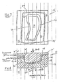
- Figure 3 is a top view of the lower mold of Fig. 1 viewed along line 3-3 of Fig. 1; and
- Figure 4 is a diagrammatic, sectional view of another form of the apparatus of the present invention.
- The diagrammatic, sectional views of Figures 1 and 2 depict a mold shown generally at 10 having an
upper mold portion 12 and alower mold portion 14. Conveniently, such mold portions generally are heated by conventional press platens or by the inclusion of resistance heaters or by circulating heat transfer fluids within chambers in the mold (not shown), as is well known and widely used in the art. - The upper and lower mold portions include shaped
internal surfaces article cavity 20 in Figure 2. -
Upper mold portion 12 inlcudes means to pass therethrough a pressurized gas, for example, air, argon, nitrogen, etc., from a source (not shown) such as through a conduit 22. Gas flow through conduit 22 is controlled by a valve andcontrol 23 as well known in the art, for example based on applied force limits sensed between upper and lower mold portions upon closure. The gas source, for example, can be a tank of pressurized gas connected to an external end of conduit 22 for such purpose.Upper mold portion 12 includes a wall or walls 24 in Figure 1 through which conduit 22 is open in the embodiment of Figs. 1 and 2. Wall 24, which is contiguous withinternal surface 16, cooperates with awall 26 oflower mold portion 14 to define amatrix reservoir 28, as shown in Figure 2, when the upper and lower mold portions are in the closed position as shown in that Figure 2.Wall 26 is contiguous withinternal surface 18 of the lower mold portion. The upper and lower mold portions are designed and constructed to provide internal clearance between internal walls and surfaces of the upper and lower mold portions in the closed position. This provides afluid flow path 30, for example about 0.005 inch tool clearance, generally circumferentially disposed aboutarticle cavity 20, enabling fluid flow communication betweenreservoir 28 andarticle cavity 20 when the mold portions are brought into registry. For example, such registry can be brought about through the application of mechanical force or clamping pressure represented by arrows 32A and 32B, Fig. 2. One of the mold portions, in this embodimentlower mold portion 14, is provided with a gas seal, shown generally at 34, about the periphery of itssurface 36, and shown in Figures 1 and 2 as a rubber "0" ring in a groove. A typical arrangement for such a seal inlower mold portion 14 is shown in Figure 3 which is a diagrammatic top view of thelower mold portion 14 viewed along line 3-3 of Figure 1. - In the conduct of the method of the present invention utilizing the apparatus embodiment of Figs. 1, 2 and 3, a fiber preform is prepared consistent with the shape of
article cavity 20. Typically, a plurability of precut sheets of a fiber bonded structure, for example using a resin such as epoxy, bonded with fibers, such as graphite, glass, boron, etc. are stacked to approximate the shape of an article to be produced. Methods and apparatus for such a preparation are described widely in the art. For example, U.S. Patent 3,649,425 - Alexander (issued March 14, 1972) is typical of a composite metal matrix fiber reinforced bonded arrangement, and U.S. Patent 3,892,612 - Carlson, et al. (issued July 1, 1975) and U.S. Patent 4,271,116 - Jones (issued June 2, 1981) are typical of composite fiber reinforced bonded structures and methods in which resin is, at least in part, the matrix. The prior art patents, describe cutting and stacking of appropriately shaped plies in the manufacture of a shaped article such as a blade for a gas turbine engine. The disclosures of each of the above identified patents are hereby incorporated herein by reference. - As is known and used in the art, in order to prepare, initially, each ply for stacking prior to placement of the assembled stack in the forming mold such as 10 in Figs. 1 and 2, each ply generally is more accurately trimmed in a cutting press. Then the plies are stacked in a preselected order and arrangement, and such a preform is placed and aligned in
lower mold portion 14 oninternal surface 18 as indicated at 19 in Fig. 2. Conveniently,lower mold portion 14 as well asupper mold portion 12 are preheated to a desired processing temperature, as will be discussed in more detail later herein in connection with the present invention. Then the mold is closed onpreform 19 as by bringing the upper and lower mold portions into registry as shown in Figure 2 and holding them together by a force such as shown by arrows 32A and 32B, one of which can be a reaction force. The application of heat and pressure forms and bonds together the plies of the preform to provide a consolidated article shape. - The prior art conventional compression molding of preimpregnated composite materials has involved very accurate mold temperature control and precise closing of the mold based on the rheological behavior (viscosity/gelation times) of the particular resin matrix batch. Highly expensive computer controlled press and molding apparatus is required to achieve sophisticated process parameters necessary to attempt to produce high quality, void-free composite articles. For example, one such arrangement is shown in the above incorporated U.S. Patent 4,455,268 - Hindricks et al, issued June 19, 1984. The mold closure cycles are comparatively long to be able to close the mold slowly during the resin's highly viscous phase without disturbing the fibers of the reinforcement. Another system for controlling a resin process is shown in U.S. Patent 4,480,981 - Togawa et al, issued November 6, 1984, the disclosure of which is hereby incorporated herein by reference.
- As an example of a prior molding process utilizing a commercially available resin marketed as Ferro CE 9220 epoxy resin, a temperature of 240°F was established based on a 30 minute mold closure cycle which initially allows first fairly rapid approach to closure and rapid expulsion of the excess resin during the resin's low viscosity stage without disturbing the fiber/ply array and then slowly fully closing during the resin's higher viscosity phase to produce nominally void free articles. In such a cycle there is a critical relationship between resin gelation time (related to viscosity) and mold closure. The critical processing window with that resin between rapid and slow closure was demonstrated to span about 8 minutes at the molding temperature of about 240°F. An increase in molding temperature, resulting in a more rapid gelation of the resin, increases the critically of the window, for example to a span of about 40 seconds at 300°F. Yet a higher molding temperature in combination with a more rapid mold closure could significantly increase production and reduce production costs which can be labor intensive.
- The method of the present invention provides such an improvement without causing fibers or plies to be washed or wrinkled especially as the resin viscosity increases. According to the present invention, the mold portions, which are heated at a higher than normal processing temperature, for example in the range of about 280-350°F using the CE 9220 epoxy resin, are closed rapidly into full registry as shown in Figure 2. In one example a loading force of up to about 330,000 lbs was used. For example, such closure can be accomplished in the range of about 7-12 minutes at those temperatures rather than the previous about 30 minutes required for a nominally void free article. In the method of the present invention, in order to avoid the formation of voids, pores and other discontinuities in the molded article, promptly upon closure or registry of the mold portions, while the resin is in its low viscosity phase and well prior to extensive resin gelation, a gaseous back pressure, for example in the range of about 200-300 psi and typically 240 psi, was applied to excess resin (or matrix) expelled into an adjoining reservoir, such as 28 in Fig. 2. Such back pressure forces or presses the excess resin back into the article cavity and about
preform 19 thereby to fill voids, and discontinuities and to compress any air or other gas bubbles entrapped within the matrix. The higher processing temperature and the resultant lower resin viscosity avoids washing or other undesirable movement of the reinforcing fibers or wrinkling of the plies, associated with such rapid mold closure or high processing temperatures, or their combinations. In a specific example utilizing the CE 9220 resin system at a 275°F mold/processing temperature and such rapid mold closure followed by prompt gaseous back pressure at 240 psi, molded articles were removed from the mold after as little as 45 minutes compared to the conventional process at 240°F temperature requiring about 1.5-2 hours of mold exposure. The present invention has overcome the practical infeasibility of prior processing at higher temperatures based on the very narrow processing windows at such temperatures associated with resin gelation. - After the rapid processing according to the method of the present invention, the mold portions are separated and the molded article is withdrawn. Thereafter, such article can be post cured, for example, such as placing in an oven in the range of about 275-350°F for about 1-12 hours, depending on the oven temperature, to further polymerize the resin matrix of the article. Then flash removal, trimming and benching can be conducted, as necessary and well known in the art.
- Another form of the apparatus of the present invention is shown in the diagrammatic, sectional view of Figure 4 in which like reference numbers to those of Figs. 1 and 2 are used. In this embodiment, mold 10 includes, in addition to the elements described in connection with Figs. 1 and 2, a resin injection conduit 40 open at one end into
reservoir 28 formed bywalls 24 and 26 respectively of upper andlower mold portions wall 26 for convenience. However, it will be recognized by those skilled in the art that conduit 40, like conduit 22, can be located in either or the same mold portion so long as they provide their respective functions in respect toreservoir 28; conduit 22 to gas pressurize the resin in the reservoir towardfluid flow path 30 and conduit 40 to inject resin into the reservoir, as appropriate to the specific process used. In addition, a discharge conduit 42, shown in Fig. 4 to be located for convenience throughlower mold portion 14, connectsarticle cavity 20 to the outside of the mold. Flow through resin injection conduit 40 and discharge conduit 42 can be controlled and coordinated through theirrespective valves 44 and 46. As is well known, for example as included in some of the above incorporated patents, a central process control, using state of the art sensors, timers, etc., can be used to control the various movements and functions of the apparatus of the drawings, includingvalves lower mold portions - Conduit 40 can be part of the pressurized resin injection molding system, sometimes referred to in the art as Resin Transfer Molding or RTM. In one form of such a system, resin in a closed container is pressurized by air to transfer the resin from the container through a conduit, such as 40 in Fig. 4, into a vented mold cavity. Prior to injection, an array of dry fibers or fabric is placed in the mold article cavity as a
preform 19 and then the injected resin is moved about and through the fibers while the resin is at low viscosity. The present invention can be used in conjunction with such a RTM system, for example in the embodiment of Fig. 4. In that form of the present invention, resin is injected through conduit 40, when the upper and lower mold portions are closed, intoreservoir 28, throughfluid flow path 30 and intoarticle cavity 20 about a fiber network or preform 19 disposed therein. Then with excess resin inreservoir 28, application of gas pressure through conduit 22 forces excess resin to flow back intoarticle cavity 20, as described above, and further to sweep entrapped air/gas bubbles in the article cavity out through discharge conduit 42 along with some excess resin. In this way, an article nominally free of voids, pores or other discontinuities or imperfections is produced in a more rapid, efficient and lower cost method. - The above embodiments have been described in connection with the use of resin, for example epoxy, as the matrix. However, other matrix materials, for example metals, for example aluminum or its alloys, or ceramics, for example QF180 Fiberfrax material with an appropriate ceramic binder, can be used through appropriate adjustment of process parameters and materials of apparatus construction. As was mentioned above, a wide variety of fibers and fabrics, commonly used in the art, for example in the dry or partially bonded condition, can be used with the matrix material selected for the intended article use. Although the present invention has been described through the detailed embodiments, those skilled in the art will readily recognize the variety of other forms within the scope of the appended claims.
Claims (9)
placing in a forming mold cavity a preform which includes at least a fiber reinforcement arrangement;
closing the mold to define an article cavity about the preform;
flowing a matrix material about the mold cavity and preform to generally fill the article cavity, and providing excess fluid matrix material outside of the article cavity and in fluid flow relationship with the article cavity;
applying gas pressure to the excess fluid matrix material to force excess material into the article cavity; and
maintaining the gas pressure while solidifying the matrix material.
placing in a forming mold cavity a fiber reinforced, resin bonded preform;
closing the mold to define an article cavity about the preform;
applying clamping pressure to hold the mold in the closed position while applying heat to the preform within the mold sufficient to flow resin from the resin bonded preform, prior to polymerization, about the interior of the article cavity and to expel excess resin into a resin reservoir in fluid flow relationship with the article cavity;
applying gas pressure to the excess resin in the reservoir to press excess resin back into the article cavity; and then,
maintaining the gas pressure until the resin has polymerized sufficiently to remove the article from the mold cavity.
the resin in the resin bonded preform is an epoxy resin;
the heat applied to the preform is in the range of about 280 - 350°F; and
the closing of the mold is accomplished in the range of about 7 - 12 minutes.
placing in a forming mold cavity a fiber reinforcement array as a preform;
closing the mold to define an article cavity about the preform;
applying clamping pressure to hold the mold in the closed position while applying heat to the article cavity;
injecting fluid resin into the article cavity about the interior of the cavity and about the fiber reinforcement array, and into an excess resin reservoir in fluid flow relationship with the article cavity;
applying gas pressure to excess resin in the reservoir to press excess resin into the article cavity; and then,
maintaining the gas pressure until the resin has polymerized sufficiently to remove the article from the mold cavity.
placing in a forming mold cavity a fiber reinforced, metal bonded preform;
closing the mold to define an article cavity about the preform;
applying clamping pressure to hold the mold in the closed position while applying heat to the preform within the mold sufficient to melt metal of the preform and to flow the melted metal about the interior of the article cavity and to expel excess melted metal into a metal reservoir in fluid flow relationship with the article cavity;
applying gas pressure to the excess melted metal in the reservoir to press excess melted metal back into the article cavity; and then
maintaining the gas pressure until the melted metal has solidified sufficiently to remove the article from the mold cavity.
a matrix reservoir connected in fluid flow relationship with the article cavity and adapted to hold excess matrix material when the mold portions are in position together; and
means to gas pressurize the matrix reservoir to press the matrix in a fluid condition into the article cavity.
means to introduce fluid matrix material into the article cavity; and
means to discharge excess fluid matrix material and entrapped gas from the article cavity.
Applications Claiming Priority (2)
| Application Number | Priority Date | Filing Date | Title |
|---|---|---|---|
| US13147387A | 1987-12-10 | 1987-12-10 | |
| US131473 | 1987-12-10 |
Publications (2)
| Publication Number | Publication Date |
|---|---|
| EP0320302A2 true EP0320302A2 (en) | 1989-06-14 |
| EP0320302A3 EP0320302A3 (en) | 1992-01-02 |
Family
ID=22449616
Family Applications (1)
| Application Number | Title | Priority Date | Filing Date |
|---|---|---|---|
| EP19880311715 Withdrawn EP0320302A3 (en) | 1987-12-10 | 1988-12-09 | Method and apparatus for making a fiber reinforced composite article |
Country Status (2)
| Country | Link |
|---|---|
| EP (1) | EP0320302A3 (en) |
| JP (1) | JPH01221228A (en) |
Cited By (12)
| Publication number | Priority date | Publication date | Assignee | Title |
|---|---|---|---|---|
| FR2675073A1 (en) * | 1991-04-09 | 1992-10-16 | Normandie Const Meca | INTERMEDIATE PLATE FOR THE MANUFACTURE OF LARGE-SIZED PANELS OF FIBER-CEMENT MATERIAL, AND METHOD AND MOLD FOR MANUFACTURING THE SAME. |
| EP0533418A1 (en) * | 1991-09-17 | 1993-03-24 | Ford Motor Company Limited | Moulding A Reinforced Plastics Component |
| US5198173A (en) * | 1990-12-13 | 1993-03-30 | E. I. Du Pont De Nemours And Company | Process for preparing advanced composite structures |
| EP0539182A1 (en) * | 1991-10-25 | 1993-04-28 | Mitsubishi Chemical Corporation | Process for producing fibre-reinforced resin mouldings |
| EP0648594A2 (en) * | 1993-10-15 | 1995-04-19 | CENTRO SVILUPPO SETTORI IMPIEGO S.r.l. | Device for moulding articles of composite material and process using such a device |
| AT413704B (en) * | 2004-06-23 | 2006-05-15 | Arc Leichtmetallkompetenzzentrum Ranshofen Gmbh | CARBON FIBER REINFORCED LIGHT METAL PART AND METHOD FOR THE PRODUCTION THEREOF |
| DE102005053691A1 (en) * | 2005-11-10 | 2007-05-16 | Airbus Gmbh | Tool for resin transfer molding process |
| DE102005053690A1 (en) * | 2005-11-10 | 2007-05-31 | Airbus Deutschland Gmbh | Tool, assembly and method for manufacturing a component, component |
| WO2013068666A1 (en) * | 2011-11-08 | 2013-05-16 | Snecma | Pressure holding device for producing composite components by the injection moulding of resin, and associated method |
| GB2500601A (en) * | 2012-03-26 | 2013-10-02 | Gurit Uk Ltd | Press moulding apparatus and method |
| CN104385611A (en) * | 2014-10-16 | 2015-03-04 | 烟台正海汽车内饰件有限公司 | Sprayed product, and production method and special die thereof |
| CN108501406A (en) * | 2017-02-28 | 2018-09-07 | 株式会社斯巴鲁 | The manufacturing method of fiber reinforced composite material |
Families Citing this family (3)
| Publication number | Priority date | Publication date | Assignee | Title |
|---|---|---|---|---|
| US7419627B2 (en) * | 2002-09-13 | 2008-09-02 | Northrop Grumman Corporation | Co-cured vacuum-assisted resin transfer molding manufacturing method |
| EP3024627B1 (en) * | 2013-07-26 | 2020-01-15 | Magna International Inc. | Mould arrangement and method for compression moulding fiber reinforced preforms |
| CN113500799A (en) * | 2016-08-31 | 2021-10-15 | 哈尔滨玻璃钢研究院有限公司 | Preform for composite hub molding and hub molding method |
Citations (10)
| Publication number | Priority date | Publication date | Assignee | Title |
|---|---|---|---|---|
| US2958621A (en) * | 1956-11-20 | 1960-11-01 | Goodyear Aircraft Corp | Method of making a dome-like body of plastic reinforced fibers |
| FR2098395A1 (en) * | 1970-07-14 | 1972-03-10 | United Kingdom Government | |
| US3970136A (en) * | 1971-03-05 | 1976-07-20 | The Secretary Of State For Defence In Her Britannic Majesty's Government Of The United Kingdom Of Great Britain And Northern Ireland | Method of manufacturing composite materials |
| EP0033638A1 (en) * | 1980-02-01 | 1981-08-12 | Ford Motor Company Limited | Producing compression molded fibre reinforced plastics panel |
| WO1983002782A1 (en) * | 1982-02-08 | 1983-08-18 | Booth, Stuart, Eric | Improvements in or relating to fibre-reinforced metals |
| JPS60155438A (en) * | 1984-01-26 | 1985-08-15 | Toshiba Corp | Manufacture of fiber-reinforced plastic container |
| DE3504118C1 (en) * | 1985-02-07 | 1985-10-31 | Daimler-Benz Ag, 7000 Stuttgart | Process for the production of fiber-reinforced light metal castings |
| WO1985005069A1 (en) * | 1984-05-09 | 1985-11-21 | Hughes Aircraft Company | Method of fabricating composite or encapsulated articles |
| EP0172050A1 (en) * | 1984-07-25 | 1986-02-19 | Regie Nationale Des Usines Renault | Method of moulding pre-impregnated articles consisting of oriented fibres |
| EP0271222A2 (en) * | 1986-11-12 | 1988-06-15 | Alcan International Limited | Production of metal matrix composites |
-
1988
- 1988-12-09 JP JP63310272A patent/JPH01221228A/en active Pending
- 1988-12-09 EP EP19880311715 patent/EP0320302A3/en not_active Withdrawn
Patent Citations (10)
| Publication number | Priority date | Publication date | Assignee | Title |
|---|---|---|---|---|
| US2958621A (en) * | 1956-11-20 | 1960-11-01 | Goodyear Aircraft Corp | Method of making a dome-like body of plastic reinforced fibers |
| FR2098395A1 (en) * | 1970-07-14 | 1972-03-10 | United Kingdom Government | |
| US3970136A (en) * | 1971-03-05 | 1976-07-20 | The Secretary Of State For Defence In Her Britannic Majesty's Government Of The United Kingdom Of Great Britain And Northern Ireland | Method of manufacturing composite materials |
| EP0033638A1 (en) * | 1980-02-01 | 1981-08-12 | Ford Motor Company Limited | Producing compression molded fibre reinforced plastics panel |
| WO1983002782A1 (en) * | 1982-02-08 | 1983-08-18 | Booth, Stuart, Eric | Improvements in or relating to fibre-reinforced metals |
| JPS60155438A (en) * | 1984-01-26 | 1985-08-15 | Toshiba Corp | Manufacture of fiber-reinforced plastic container |
| WO1985005069A1 (en) * | 1984-05-09 | 1985-11-21 | Hughes Aircraft Company | Method of fabricating composite or encapsulated articles |
| EP0172050A1 (en) * | 1984-07-25 | 1986-02-19 | Regie Nationale Des Usines Renault | Method of moulding pre-impregnated articles consisting of oriented fibres |
| DE3504118C1 (en) * | 1985-02-07 | 1985-10-31 | Daimler-Benz Ag, 7000 Stuttgart | Process for the production of fiber-reinforced light metal castings |
| EP0271222A2 (en) * | 1986-11-12 | 1988-06-15 | Alcan International Limited | Production of metal matrix composites |
Non-Patent Citations (2)
| Title |
|---|
| PATENT ABSTRACTS OF JAPAN, Vol. 9, No. 322 (M-440)(2045), 18th December 1985; & JP-A-60 155 438 (TOSHIBA) 15-08-1985, the whole document. * |
| PATENT ABSTRACTS OF JAPAN, vol. 9, no. 322 (M-440)[2045], 18th December 1985; & JP-A-60 155 438 (TOSHIBA) 15-08-1985 * |
Cited By (21)
| Publication number | Priority date | Publication date | Assignee | Title |
|---|---|---|---|---|
| US5198173A (en) * | 1990-12-13 | 1993-03-30 | E. I. Du Pont De Nemours And Company | Process for preparing advanced composite structures |
| EP0512874A1 (en) * | 1991-04-09 | 1992-11-11 | Constructions Mecaniques De Normandie | Spacer element for the production of large dimension fiber-cement panels, the process of manufacture and the mould |
| FR2675073A1 (en) * | 1991-04-09 | 1992-10-16 | Normandie Const Meca | INTERMEDIATE PLATE FOR THE MANUFACTURE OF LARGE-SIZED PANELS OF FIBER-CEMENT MATERIAL, AND METHOD AND MOLD FOR MANUFACTURING THE SAME. |
| EP0533418A1 (en) * | 1991-09-17 | 1993-03-24 | Ford Motor Company Limited | Moulding A Reinforced Plastics Component |
| EP0539182A1 (en) * | 1991-10-25 | 1993-04-28 | Mitsubishi Chemical Corporation | Process for producing fibre-reinforced resin mouldings |
| EP0648594A2 (en) * | 1993-10-15 | 1995-04-19 | CENTRO SVILUPPO SETTORI IMPIEGO S.r.l. | Device for moulding articles of composite material and process using such a device |
| EP0648594A3 (en) * | 1993-10-15 | 1995-10-25 | Sviluppo Settori Impiego Srl | Device for moulding articles of composite material and process using such a device. |
| AT413704B (en) * | 2004-06-23 | 2006-05-15 | Arc Leichtmetallkompetenzzentrum Ranshofen Gmbh | CARBON FIBER REINFORCED LIGHT METAL PART AND METHOD FOR THE PRODUCTION THEREOF |
| US8858218B2 (en) | 2005-11-10 | 2014-10-14 | Airbus Operations Gmbh | Tool for a resin transfer moulding method |
| DE102005053691A1 (en) * | 2005-11-10 | 2007-05-16 | Airbus Gmbh | Tool for resin transfer molding process |
| DE102005053690A1 (en) * | 2005-11-10 | 2007-05-31 | Airbus Deutschland Gmbh | Tool, assembly and method for manufacturing a component, component |
| US9352517B2 (en) | 2005-11-10 | 2016-05-31 | Airbus Deutschland Gmbh | Resin-transfer-moulding method |
| WO2013068666A1 (en) * | 2011-11-08 | 2013-05-16 | Snecma | Pressure holding device for producing composite components by the injection moulding of resin, and associated method |
| CN103917357A (en) * | 2011-11-08 | 2014-07-09 | 斯奈克玛 | Pressure holding device for producing composite components by the injection moulding of resin, and associated method |
| CN103917357B (en) * | 2011-11-08 | 2016-11-23 | 斯奈克玛 | The pressure being produced composite component by resin injection moulding keeps equipment and correlation technique |
| US9517581B2 (en) | 2011-11-08 | 2016-12-13 | Snecma | Pressure-maintenance device for producing composite parts by resin injection and associated method |
| RU2616066C2 (en) * | 2011-11-08 | 2017-04-12 | Снекма | Pressure holding device for manufacture of composite parts by resin injection and appropriate method |
| GB2500601B (en) * | 2012-03-26 | 2014-10-22 | Gurit Uk Ltd | Press moulding apparatus and method |
| GB2500601A (en) * | 2012-03-26 | 2013-10-02 | Gurit Uk Ltd | Press moulding apparatus and method |
| CN104385611A (en) * | 2014-10-16 | 2015-03-04 | 烟台正海汽车内饰件有限公司 | Sprayed product, and production method and special die thereof |
| CN108501406A (en) * | 2017-02-28 | 2018-09-07 | 株式会社斯巴鲁 | The manufacturing method of fiber reinforced composite material |
Also Published As
| Publication number | Publication date |
|---|---|
| EP0320302A3 (en) | 1992-01-02 |
| JPH01221228A (en) | 1989-09-04 |
Similar Documents
| Publication | Publication Date | Title |
|---|---|---|
| US5023041A (en) | Method for making a fiber reinforced composite article | |
| EP0320302A2 (en) | Method and apparatus for making a fiber reinforced composite article | |
| US5738818A (en) | Compression/injection molding of polymer-derived fiber reinforced ceramic matrix composite materials | |
| US9643363B2 (en) | Manufacture of a structural composites component | |
| US5851336A (en) | Resin transfer molding in combination with honeycomb core | |
| US6156146A (en) | Resin transfer molding with honeycomb core and core filler | |
| US5433915A (en) | Manufacturing method of composite articles from prepregs which avoids internal defects | |
| EP0433857B1 (en) | Reaction injection molding apparatus for forming fibre-reinforced molded article | |
| US4624820A (en) | Molding of composite materials | |
| US4389367A (en) | Fluid molding system | |
| MX2012003153A (en) | An improved method of and apparatus for making a composite material. | |
| CN110027227A (en) | Bag press-resin Transfer molding mold, molding machine and forming method | |
| CN112497786A (en) | Forming method and die for carbon fiber automobile parts | |
| GB2147850A (en) | "Fibre-reinforced thermoplastic laminate | |
| US3780151A (en) | Evacuated,displacement compression molding | |
| FR3008642A1 (en) | INJECTION MOLDING PROCESS OF A COMPOSITE MATERIAL PART WITH PRIOR PRE-CONSOLIDATION OF THE FIBROUS PREFORM | |
| CN109318511A (en) | A kind of low cost preparation method of complicated inner cavity composite product | |
| JP4292971B2 (en) | FRP manufacturing method and manufacturing apparatus | |
| EP3210739B1 (en) | Composite-material moulding method and moulding device | |
| CN111113954B (en) | Preparation method of low-density heat-proof composite material revolving body part | |
| US5609805A (en) | Process for producing a composite part by compression molding | |
| JPS5923552B2 (en) | In-mold coating equipment and method | |
| CN113386374B (en) | Mold for improving internal quality of liquid molding composite material and control method | |
| IT201600105326A1 (en) | METHOD AND APPARATUS FOR PRODUCING A CLOSED CABLE BODY IN COMPOSITE MATERIAL | |
| WO1996022871A1 (en) | Method of resin transfer molding |
Legal Events
| Date | Code | Title | Description |
|---|---|---|---|
| PUAI | Public reference made under article 153(3) epc to a published international application that has entered the european phase |
Free format text: ORIGINAL CODE: 0009012 |
|
| AK | Designated contracting states |
Kind code of ref document: A2 Designated state(s): DE FR GB IT |
|
| PUAL | Search report despatched |
Free format text: ORIGINAL CODE: 0009013 |
|
| AK | Designated contracting states |
Kind code of ref document: A3 Designated state(s): DE FR GB IT |
|
| 17P | Request for examination filed |
Effective date: 19911220 |
|
| 17Q | First examination report despatched |
Effective date: 19930422 |
|
| STAA | Information on the status of an ep patent application or granted ep patent |
Free format text: STATUS: THE APPLICATION IS DEEMED TO BE WITHDRAWN |
|
| 18D | Application deemed to be withdrawn |
Effective date: 19940226 |