EP0172050A1 - Method of moulding pre-impregnated articles consisting of oriented fibres - Google Patents
Method of moulding pre-impregnated articles consisting of oriented fibres Download PDFInfo
- Publication number
- EP0172050A1 EP0172050A1 EP85401277A EP85401277A EP0172050A1 EP 0172050 A1 EP0172050 A1 EP 0172050A1 EP 85401277 A EP85401277 A EP 85401277A EP 85401277 A EP85401277 A EP 85401277A EP 0172050 A1 EP0172050 A1 EP 0172050A1
- Authority
- EP
- European Patent Office
- Prior art keywords
- mold
- press
- fibers
- resin
- product
- Prior art date
- Legal status (The legal status is an assumption and is not a legal conclusion. Google has not performed a legal analysis and makes no representation as to the accuracy of the status listed.)
- Withdrawn
Links
Images

Classifications
-
- B—PERFORMING OPERATIONS; TRANSPORTING
- B29—WORKING OF PLASTICS; WORKING OF SUBSTANCES IN A PLASTIC STATE IN GENERAL
- B29D—PRODUCING PARTICULAR ARTICLES FROM PLASTICS OR FROM SUBSTANCES IN A PLASTIC STATE
- B29D99/00—Subject matter not provided for in other groups of this subclass
- B29D99/0003—Producing profiled members, e.g. beams
- B29D99/0007—Producing profiled members, e.g. beams having a variable cross-section
-
- B—PERFORMING OPERATIONS; TRANSPORTING
- B29—WORKING OF PLASTICS; WORKING OF SUBSTANCES IN A PLASTIC STATE IN GENERAL
- B29C—SHAPING OR JOINING OF PLASTICS; SHAPING OF MATERIAL IN A PLASTIC STATE, NOT OTHERWISE PROVIDED FOR; AFTER-TREATMENT OF THE SHAPED PRODUCTS, e.g. REPAIRING
- B29C70/00—Shaping composites, i.e. plastics material comprising reinforcements, fillers or preformed parts, e.g. inserts
- B29C70/04—Shaping composites, i.e. plastics material comprising reinforcements, fillers or preformed parts, e.g. inserts comprising reinforcements only, e.g. self-reinforcing plastics
- B29C70/28—Shaping operations therefor
- B29C70/40—Shaping or impregnating by compression not applied
- B29C70/42—Shaping or impregnating by compression not applied for producing articles of definite length, i.e. discrete articles
- B29C70/46—Shaping or impregnating by compression not applied for producing articles of definite length, i.e. discrete articles using matched moulds, e.g. for deforming sheet moulding compounds [SMC] or prepregs
Definitions
- the present invention relates to a hot press molding process for oriented fiber and organic matrix prepregs.
- Composite materials with oriented fibers and an organic matrix have a great capacity for absorbing energy by elastic deformation.
- the object of the present invention is the production under industrial manufacturing conditions of parts having greater freedom of shape, by a hot press molding process from sheets of reinforcing fibers.
- An additional advantage lies in the fact that the reinforcing fibers are stretched in the direction of their work, thus reinforcing the mechanical properties of the product obtained.
- a mold can be used steel as shown in figure 2.
- the die 1 placed on the lower plate 2 of a press which is not shown and is known per se, has the convex curvature; the punch 3 which has the concave curvature is mounted on the upper plate 4.
- a thermocouple 8 is placed in the die 1 and a displacement sensor 9 is interposed between the plates 2 and 4.
- FIGS. 4 and 5 The operation of the device below is shown diagrammatically in FIGS. 4 and 5.
- the closing force of the shaping press is used here for their installation.
- this action allows a tension of the fibers in their longitudinal direction and, simultaneously, an evacuation of the excess resin voluntarily brought in the direction of the tanks 7 as well as air bubbles which could have been included.
- a composite material is thus obtained which can comprise more than 60% of fibers by volume and devoid of porosity.
- the prepreg used may consist of E glass fibers and DGEBA type epoxy resin and is manufactured by Ste BROCHIER INDUSTRIE.
- the target rate of the resin, at room temperature, is high enough for the prepreg to be handled and malleable.
- a preliminary blank can be made by stacking several layers of prepreg.
- the mold is thermo-regulated at a temperature between 120 and 200 ° C.
- the plates 2-4 of the press continue to approach slowly, until the two parts 1-3 of the mold are no longer separated except by the stops 6 which determine the final thickness of the part.
- the resin enters its hardening phase, the progress of which is followed using thermocouple 8, the polymerization being accompanied by an exothermic peak, followed a few minutes before the opening of the press and demolding. of the room.
- the variation rule for these two parameters is calculated according to the results to be obtained and results in significant lightening of the blade, compared to a blade of constant width and height, with equivalent mechanical performance.
- a damage start detector this may be constituted by an electric thermocouple 12 preferably located mid-length of the blade 10 and / or at least one surface metallization zone 13 disposed before or after the molding of the blade 1, in the most constraints.
- an abnormal heating and / or a break in the electrical circuit established in the metallized part 13 has a witness known in itself, signals to the driver the beginning of damage to the blade at the level of said detectors, still allowing the vehicle to move, but requiring for safety reasons the immediate replacement of the blade in question.
Abstract
Description
La présente invention se rapporte à un procédé de moulage à la presse à chaud de préimprégnés à fibres orientées et à matrice organique.The present invention relates to a hot press molding process for oriented fiber and organic matrix prepregs.
Les matériaux composites à fibres orientées et à matrice organique ont une grande capacité d'absorption d'énergie par déformation élastique. De plus, dans le cas d'une pièce surchargée, il est possible d'obtenir un endommagement progressif au lieu d'une rupture brutale.Composite materials with oriented fibers and an organic matrix have a great capacity for absorbing energy by elastic deformation. In addition, in the case of an overloaded part, it is possible to obtain progressive damage instead of a sudden rupture.
Ces avantages sont mis à profit dans des applications telles que des pare-chocs, des lames de ressort, des renforts de structure et autres pièces de sécurité. Les meilleurs résultats sont obtenus en disposant des fibres continues orientées dans le sens des contraintes principales.These advantages are exploited in applications such as bumpers, leaf springs, structural reinforcements and other safety parts. The best results are obtained by having continuous fibers oriented in the direction of the main stresses.
Les pièces de profil et de courbure variables peuvent être fabriquées selon un procédé d'enroulement filamentaire tel que celui décrit dans le brevet 71-45 055 de la demanderesse:
- Les pièces de profil et de courbure constants peuvent être fabriquées en continu selon un procédé décrit dans le brevet 73-46 906 également de la demanderesse.
- The constant profile and curvature parts can be manufactured continuously according to a process described in patent 73-46,906 also by the applicant.
Le but de la présente invention est la réalisation dans des conditions de fabrication industrielle de pièces présentant une plus grande liberté de forme, par un procédé de moulage à la presse à chaud à partir de nappes de fibres de renforcement.The object of the present invention is the production under industrial manufacturing conditions of parts having greater freedom of shape, by a hot press molding process from sheets of reinforcing fibers.
Un avantage supplémentaire réside dans le fait que les fibres de renforcement sont tendues dans le sens de leur travail, renforçant ainsi les propriétés mécaniques du produit obtenu.An additional advantage lies in the fact that the reinforcing fibers are stretched in the direction of their work, thus reinforcing the mechanical properties of the product obtained.
L'invention sera maintenant décrite, à titre d'exemple non limitatif, au regard des figures 1 à 6 ci-jointes, qui se rapportent respectivement :
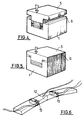
- - la figure 1, à une vue en perspective d'une lame de ressort de suspension pour véhicule utilitaire,
- - la figure 2, à un schéma selon une coupe longitudinale d'une vue de détail du dispositif permettant la mise en oeuvre du prdcédé de l'invention.
- - la figure 3, à une vue en coupe transversale d'un schéma de dispositif permettant la mise en oeuvre du procédé selon l'invention.
- - les figures 4 et 5 une vue en perspective de l'ensemble poinçon-matrice, respectivement avant et après leur rapprochement.
- - la figure 6, à une vue en perspective d'un perfectionnement du produit obtenu selon l'invention.
- FIG. 1, in a perspective view of a suspension spring leaf for a commercial vehicle,
- - Figure 2, to a diagram in a longitudinal section of a detail view of the device allowing the implementation of the prdcédé of the invention.
- - Figure 3, a cross-sectional view of a device diagram for implementing the method according to the invention.
- - Figures 4 and 5 a perspective view of the punch-die assembly, respectively before and after their approximation.
- - Figure 6, a perspective view of an improvement of the product obtained according to the invention.
Pour obtenir une lame de ressort de suspension 10 telle que représentée à la figure 1, qui est renforcée essentiellement par des fibres unidirectionnelles, longitudinales, continues et travaillant en flexion sur deux appuis disposés à ses extrémités 11, 11', on peut utiliser un moule en acier tel que représenté à la figure 2.To obtain a
La matrice 1, placée sur le plateau inférieur 2 d'une presse non figurée et connue en soi, comporte la courbure convexe ; le poinçon 3 qui présente la courbure concave, est monté sur le plateau supérieure 4. Un thermocouple 8 est disposé dans la matrice 1 et un capteur de déplacement 9 est intercalé entre les plateaux 2 et 4.The die 1, placed on the
On notera que les parties du moule correspondant aux extrémités de la lame sont ouvertes et pourvues de petits bacs 7 destinés à recevoir la résine excédentaire lors de l'opération de pressage.It will be noted that the parts of the mold corresponding to the ends of the blade are open and provided with
On voit à la figure 3 que les joints entre le poinçon 3 et la matrice 1 sont verticaux, des butées amovibles 6 permettant de limiter la course de ces éléments, réglant ainsi l'épaisseur finale des pièces moulées.We see in Figure 3 that the joints between the
Le fonctionnement du dispositif ci-dessous est schématisé aux figures 4 et 5.The operation of the device below is shown diagrammatically in FIGS. 4 and 5.
Contrairement aux procédés antérieurs selon lesquels les fibres pré- imprégnées ou imprégnées au moment du moulage sont disposés directement aux endroits à renforcer ; on utilise ici la force de fermeture de la presse conformatrice pour leur mise en place .Unlike the previous methods according to which the fibers pre-impregnated or impregnated at the time of molding are placed directly at the places to be reinforced; the closing force of the shaping press is used here for their installation.
De surcroît, cette action permet une tension des fibres selon leur sens longitudinal et, simultanément, une évacuation de l'excédent de résine volontairement apporté en direction des bacs 7 ainsi que des bulles d'air qui auraient pu être incluses.In addition, this action allows a tension of the fibers in their longitudinal direction and, simultaneously, an evacuation of the excess resin voluntarily brought in the direction of the
On obtient ainsi un matériau composite pouvant comporter plus de 60 % de fibres en volume et dépourvu de porosité.A composite material is thus obtained which can comprise more than 60% of fibers by volume and devoid of porosity.
Le préimprégné utilisé peut-être constitué de fibres de verre E et de résine époxy du type DGEBA et est fabriqué par la Ste BROCHIER INDUSTRIE.The prepreg used may consist of E glass fibers and DGEBA type epoxy resin and is manufactured by Ste BROCHIER INDUSTRIE.
Il se présente sous forme d'une bande de faible épaisseur (0,6 à 0,7 mm) et de largeur légèrement inférieure à celle de la lame de ressort qui doit être conformée, dans sa zone la plus étroite.It is in the form of a thin strip (0.6 to 0.7 mm) and of width slightly less than that of the spring leaf which must be shaped, in its narrowest zone.
La viseosite de la résine, à la température ambiante, est suffisamment élevée pour que le préimprégné soit manipulable et malléable.The target rate of the resin, at room temperature, is high enough for the prepreg to be handled and malleable.
Une ébauche préalable peut-être confectionnée en empilant plusieurs couches de préimprégné.A preliminary blank can be made by stacking several layers of prepreg.
Le moule est thermo-régulé à une température comprise entre 120 et 200°C.The mold is thermo-regulated at a temperature between 120 and 200 ° C.
Après les opérations préalables de nettoyage des empreintes 1 et 3 et d'application d'un agent de démoulage, on dispose l'ébauche ci-dessus dans la matrice 1 et on ferme la presse (figure 4), ce qui entraine le remplissage du moule (figure 5).After the preliminary operations of cleaning the
Durant cette phase, le matériau est encore à basse température, la résine ayant une viscosité élevée, on observe un fluage transversal homogène sous faible pression.During this phase, the material is still at low temperature, the resin having a high viscosity, a homogeneous transverse creep is observed under low pressure.
Quand cette phase de mise en forme de l'ébauche est terminée celle-ci offre alors un effort résistant important permettant d'accroitre la pression sur le matériau ; les fibres de verre parallèles et continues ne peuvent subir un fluage longitudinal tout en acceptant cependant une certaine précontrainte ; seuls l'excès de résine qui les lie et les bulles d'air éventuelles qui s'y trouve sont entraînés vers les extrémités du moule pourvues des bacs 7.When this phase of shaping the blank is finished, it then offers a significant resistant force making it possible to increase the pressure on the material; the parallel and continuous glass fibers cannot undergo a longitudinal creep while accepting however a certain prestress; only the excess resin which binds them and the possible air bubbles which are there are entrained towards the ends of the mold provided with
Les plateaux 2-4 de la presse continuent de se rapprocher lentement, jusqu'à ce que les deux parties 1-3 du moule ne soient plus séparées que par les butées 6 qui déterminent l'épaisseur finale de la pièce.The plates 2-4 of the press continue to approach slowly, until the two parts 1-3 of the mold are no longer separated except by the
La fin de fermeture est facilitée par la baisse de viscosité de la résine qui accompagne l'échauffement du matériau.The end of closure is facilitated by the drop in viscosity of the resin which accompanies the heating of the material.
Puis, la résine entre dans sa phase de durcissement, dont on suit l'évolution à l'aide du thermocouple 8, la polymérisation s'accompagnant d'un pic exothermique, suivi à quelques minutes de l'ouverture de la presse et du démoulage de la pièce.Then, the resin enters its hardening phase, the progress of which is followed using
La résine excédentaire ayant durci dans les bacs 7, reste soudée à la pièce finale et se trouve ainsi simultanément évacuée avec elle ; l'excès de résine sera éliminé lors des opérations de finitions habituelles.The excess resin which has hardened in the
Le type de produit obtenu par le procédé ci-dessus, et qui est illustré par la figure 1, est remarquable en ce que l'on fait évoluer sa largeur L et sa hauteur H le long de son axe longitudinal de telle façon que pour chaque section transversale donnée le produit 1 x h = 1' x h' = 1n x hn = constante, avec un maximum pour h = h' au milieu de la lame de ressort 10. La règle de variation de ces deux paramètres est calculée en fonction des résultats à obtenir et donne lieu à un allègement important de la lame, au regard d'une lame de largeur et de hauteur constante, à prestations mécaniques équivalentes.The type of product obtained by the above process, and which is illustrated in FIG. 1, is remarkable in that its width L and its height H are changed along its longitudinal axis so that for each cross section given the product 1 xh = 1 'xh' = 1 n xh n = constant, with a maximum for h = h 'in the middle of the
On peut encore améliorer le produit ci-dessus en lui intégrant, comme on le voit à la figure 6, un détecteur de début d'endommagement ; celui-ci peut-être constitué par un thermocouple électrique 12 situé de préférence à mi-longueur de la lame 10 et/ou au moins une zône de métallisation superficielle 13 disposée avant ou après le moulage de la lame 1, dans les zônes les plus contraintes.We can further improve the above product by incorporating, as seen in Figure 6, a damage start detector; this may be constituted by an
Ainsi, un échauffement anormal et/ou une rupture du circuit électrique établi dans la partie métallisée 13 reuni a un témoin connu en soi, signale au conducteur un début d'endommagement de la lame au niveau desdits détecteurs, permettant encore le déplacement du véhicule, mais imposant pour les raisons de sécurité le proche remplacement de la lame en cause.Thus, an abnormal heating and / or a break in the electrical circuit established in the
Claims (8)
Applications Claiming Priority (2)
| Application Number | Priority Date | Filing Date | Title |
|---|---|---|---|
| FR8411782A FR2568167B1 (en) | 1984-07-25 | 1984-07-25 | ORIENTED FIBER PREPREGNATES MOLDING METHOD |
| FR8411782 | 1984-07-25 |
Publications (1)
| Publication Number | Publication Date |
|---|---|
| EP0172050A1 true EP0172050A1 (en) | 1986-02-19 |
Family
ID=9306475
Family Applications (1)
| Application Number | Title | Priority Date | Filing Date |
|---|---|---|---|
| EP85401277A Withdrawn EP0172050A1 (en) | 1984-07-25 | 1985-06-25 | Method of moulding pre-impregnated articles consisting of oriented fibres |
Country Status (3)
| Country | Link |
|---|---|
| EP (1) | EP0172050A1 (en) |
| ES (1) | ES8701583A1 (en) |
| FR (1) | FR2568167B1 (en) |
Cited By (9)
| Publication number | Priority date | Publication date | Assignee | Title |
|---|---|---|---|---|
| EP0320302A2 (en) * | 1987-12-10 | 1989-06-14 | General Electric Company | Method and apparatus for making a fiber reinforced composite article |
| FR2654975A1 (en) * | 1989-11-24 | 1991-05-31 | Vollet Jerome | METHOD FOR MOLDING A PIECE OF COMPOSITE MATERIAL |
| EP0637520A2 (en) * | 1993-08-06 | 1995-02-08 | Toyota Jidosha Kabushiki Kaisha | Suspension arm made of fiber reinforced plastic and manufacturing method thereof |
| EP0851142A1 (en) * | 1996-12-24 | 1998-07-01 | Dsm N.V. | Structural spring of fibre-reinforced plastic |
| FR2774627A1 (en) * | 1998-02-10 | 1999-08-13 | Inst Francais Du Petrole | PRESS-FREE MOLDING PROCESS AND ASSOCIATED DEVICE |
| FR2797212A1 (en) * | 1999-08-06 | 2001-02-09 | Bell Helicopter Textron Inc | METHOD FOR MANUFACTURING AN OBJECT MADE OF COMPOSITE MATERIAL REINFORCED BY FIBERS, SUCH AS A PORTION OF A ROTOR BLADE FOR AN AIRCRAFT, AND OBJECT OBTAINED BY THIS PROCESS |
| WO2008055459A2 (en) * | 2006-11-06 | 2008-05-15 | Ifc Composite Gmbh | Method for producing a leaf spring from a composite fiber material containing a thermoplastic material, and leaf spring obtained by means of said method |
| WO2008055458A1 (en) * | 2006-11-06 | 2008-05-15 | Ifc Composite Gmbh | Method for producing leaf springs from a fiber composite material |
| US9463588B2 (en) | 2014-02-07 | 2016-10-11 | Todas Santos Surf, Inc. | Surf fin including injection molded pre-impregnated composite fiber matrix inserts |
Families Citing this family (1)
| Publication number | Priority date | Publication date | Assignee | Title |
|---|---|---|---|---|
| FR2587649B1 (en) * | 1985-09-20 | 1988-05-27 | Renault | PROCESS FOR PRODUCING ORIENTED FIBER COMPOSITE MATERIAL PRODUCTS, PARTICULARLY SPRING BLADES, PARTICULARLY FOR MOTOR VEHICLES AND PRODUCTS THEREOF |
Citations (7)
| Publication number | Priority date | Publication date | Assignee | Title |
|---|---|---|---|---|
| US2621140A (en) * | 1940-08-28 | 1952-12-09 | Comp Generale Electricite | Method for molding propeller blades |
| GB781333A (en) * | 1950-04-06 | 1957-08-21 | Elmer Pershing Warnken | Improvements relating to blades of air-foil configuration and the method of making same |
| GB2041489A (en) * | 1978-09-29 | 1980-09-10 | Courtaulds Ltd | Composite elongate element |
| GB2100835A (en) * | 1981-06-15 | 1983-01-06 | Budd Co | Non-metallic leaf spring |
| GB2101033A (en) * | 1981-06-24 | 1983-01-12 | Laader Berg Ltd A S | Method of and apparatus for producing fibre-reinforced articles |
| WO1983000118A1 (en) * | 1981-06-30 | 1983-01-20 | Boeing Co | Method of manufacturing a preform from fiber reinforced composite material |
| FR2513564A1 (en) * | 1981-09-26 | 1983-04-01 | Kawasaki Yuko Kk | METHOD FOR MANUFACTURING MOLDED PARTS FROM COMPOSITE MATERIAL SHEET WITH EXACT ADJUSTMENT OF THE DISPLACEMENT SEMI-MOLD PARALLELISM |
-
1984
- 1984-07-25 FR FR8411782A patent/FR2568167B1/en not_active Expired
-
1985
- 1985-06-25 EP EP85401277A patent/EP0172050A1/en not_active Withdrawn
- 1985-07-23 ES ES545476A patent/ES8701583A1/en not_active Expired
Patent Citations (7)
| Publication number | Priority date | Publication date | Assignee | Title |
|---|---|---|---|---|
| US2621140A (en) * | 1940-08-28 | 1952-12-09 | Comp Generale Electricite | Method for molding propeller blades |
| GB781333A (en) * | 1950-04-06 | 1957-08-21 | Elmer Pershing Warnken | Improvements relating to blades of air-foil configuration and the method of making same |
| GB2041489A (en) * | 1978-09-29 | 1980-09-10 | Courtaulds Ltd | Composite elongate element |
| GB2100835A (en) * | 1981-06-15 | 1983-01-06 | Budd Co | Non-metallic leaf spring |
| GB2101033A (en) * | 1981-06-24 | 1983-01-12 | Laader Berg Ltd A S | Method of and apparatus for producing fibre-reinforced articles |
| WO1983000118A1 (en) * | 1981-06-30 | 1983-01-20 | Boeing Co | Method of manufacturing a preform from fiber reinforced composite material |
| FR2513564A1 (en) * | 1981-09-26 | 1983-04-01 | Kawasaki Yuko Kk | METHOD FOR MANUFACTURING MOLDED PARTS FROM COMPOSITE MATERIAL SHEET WITH EXACT ADJUSTMENT OF THE DISPLACEMENT SEMI-MOLD PARALLELISM |
Cited By (16)
| Publication number | Priority date | Publication date | Assignee | Title |
|---|---|---|---|---|
| EP0320302A2 (en) * | 1987-12-10 | 1989-06-14 | General Electric Company | Method and apparatus for making a fiber reinforced composite article |
| EP0320302A3 (en) * | 1987-12-10 | 1992-01-02 | General Electric Company | Method and apparatus for making a fiber reinforced composite article |
| FR2654975A1 (en) * | 1989-11-24 | 1991-05-31 | Vollet Jerome | METHOD FOR MOLDING A PIECE OF COMPOSITE MATERIAL |
| EP0637520A2 (en) * | 1993-08-06 | 1995-02-08 | Toyota Jidosha Kabushiki Kaisha | Suspension arm made of fiber reinforced plastic and manufacturing method thereof |
| EP0637520A3 (en) * | 1993-08-06 | 1995-11-08 | Toyota Motor Co Ltd | Suspension arm made of fiber reinforced plastic and manufacturing method thereof. |
| US5556081A (en) * | 1993-08-06 | 1996-09-17 | Toyota Jidosha Kabushiki Kaisha | Suspension arm made of fiber reinforced plastic and manufacturing method thereof |
| EP0851142A1 (en) * | 1996-12-24 | 1998-07-01 | Dsm N.V. | Structural spring of fibre-reinforced plastic |
| BE1010823A3 (en) * | 1996-12-24 | 1999-02-02 | Dsm Nv | CONSTRUCTION FEATHER prepreg. |
| FR2774627A1 (en) * | 1998-02-10 | 1999-08-13 | Inst Francais Du Petrole | PRESS-FREE MOLDING PROCESS AND ASSOCIATED DEVICE |
| EP0936056A1 (en) * | 1998-02-10 | 1999-08-18 | Institut Francais Du Petrole | Process and apparatus for moulding without a press |
| FR2797212A1 (en) * | 1999-08-06 | 2001-02-09 | Bell Helicopter Textron Inc | METHOD FOR MANUFACTURING AN OBJECT MADE OF COMPOSITE MATERIAL REINFORCED BY FIBERS, SUCH AS A PORTION OF A ROTOR BLADE FOR AN AIRCRAFT, AND OBJECT OBTAINED BY THIS PROCESS |
| WO2008055459A2 (en) * | 2006-11-06 | 2008-05-15 | Ifc Composite Gmbh | Method for producing a leaf spring from a composite fiber material containing a thermoplastic material, and leaf spring obtained by means of said method |
| WO2008055458A1 (en) * | 2006-11-06 | 2008-05-15 | Ifc Composite Gmbh | Method for producing leaf springs from a fiber composite material |
| WO2008055459A3 (en) * | 2006-11-06 | 2008-07-03 | Ifc Composite Gmbh | Method for producing a leaf spring from a composite fiber material containing a thermoplastic material, and leaf spring obtained by means of said method |
| US9463588B2 (en) | 2014-02-07 | 2016-10-11 | Todas Santos Surf, Inc. | Surf fin including injection molded pre-impregnated composite fiber matrix inserts |
| US11738488B2 (en) | 2014-02-07 | 2023-08-29 | Todos Santos Surf, Inc. | Method of making surf fin including injection molded pre-impregnated composite fiber matrix inserts |
Also Published As
| Publication number | Publication date |
|---|---|
| ES545476A0 (en) | 1986-12-01 |
| FR2568167B1 (en) | 1986-08-29 |
| ES8701583A1 (en) | 1986-12-01 |
| FR2568167A1 (en) | 1986-01-31 |
Similar Documents
| Publication | Publication Date | Title |
|---|---|---|
| EP0141700B1 (en) | Mould for large mouldings of composite material | |
| EP2259913B1 (en) | Method and device for moulding a curved part made from composite material | |
| EP0989932B1 (en) | Method for producing a sandwich-type composite panel with articulation hinge, and resulting panel | |
| EP0172050A1 (en) | Method of moulding pre-impregnated articles consisting of oriented fibres | |
| FR2587649A1 (en) | Process for manufacturing products made from composite materials having oriented fibres, in particular leafsprings, especially for motor vehicles, and products resulting therefrom | |
| FR2806347A1 (en) | Manufacture of bath, shower tray, etc. from thermoplastic material with cellular core in single stamping operation without stretching or tearing of material | |
| EP0604298A1 (en) | Composite thermoplastic blade, in particular for helicopter shrouded tail rotor, and its manufacturing process | |
| FR2620628A2 (en) | PROCESS FOR REALIZING A SKI AND SKIING DOES ACCORDING TO THIS PROCESS | |
| FR2483343A1 (en) | PROFILES GALBES ABSORBERS OF ENERGY | |
| WO2011117546A1 (en) | Method for the continuous production of a connecting part made from composite material | |
| EP0091366A1 (en) | Pressure shaping of articles of thermosetting reinforced polymers | |
| EP0865892B1 (en) | Process for manufacturing precision hollow articles made of composite material | |
| FR2820359A1 (en) | PROCESS AND DEVICE FOR MOLDING A PART IN COMPOSITE MATERIAL, AND ULM PROPELLER HUB WHICH THEY ALLOW THEM TO MAKE | |
| WO2010092309A1 (en) | Method for making a stiffened panel made of a composite material | |
| FR3019081A1 (en) | PUNCHING METHOD OF FIBER REINFORCED RESIN PLATE AND METHOD FOR MANUFACTURING FIBER REINFORCED RESIN PRODUCT | |
| EP2569146B1 (en) | Device for manufacturing a composite part by resin injection moulding | |
| JPS6213533B2 (en) | ||
| FR2779988A1 (en) | Molding thermoplastic composites with large proportions of reinforcement | |
| KR101026962B1 (en) | Production method of bumper beam | |
| FR2686043A1 (en) | Method of producing a structural panel of the sandwich type, and panel thus obtained | |
| EP0451042A1 (en) | Mould for moulding constructional pieces in plastic material and process to realise the mould | |
| BE1005387A3 (en) | Thermoplastic plate strengthened surface and methods for its implementation. | |
| FR3051711A1 (en) | METHOD FOR MANUFACTURING EQUIPMENT PIECE | |
| EP3204219A1 (en) | Method for producing thermoplastic parts reinforced with continuous thermoplastic fibres | |
| WO2012029708A1 (en) | Method for producing compressed wood product |
Legal Events
| Date | Code | Title | Description |
|---|---|---|---|
| PUAI | Public reference made under article 153(3) epc to a published international application that has entered the european phase |
Free format text: ORIGINAL CODE: 0009012 |
|
| 17P | Request for examination filed |
Effective date: 19850629 |
|
| AK | Designated contracting states |
Designated state(s): BE DE GB IT NL SE |
|
| 17Q | First examination report despatched |
Effective date: 19871203 |
|
| STAA | Information on the status of an ep patent application or granted ep patent |
Free format text: STATUS: THE APPLICATION HAS BEEN WITHDRAWN |
|
| 18W | Application withdrawn |
Withdrawal date: 19920403 |
|
| RIN1 | Information on inventor provided before grant (corrected) |
Inventor name: ROUBINET, PIERRE |