EP0320143A2 - Pneumatic tyre - Google Patents
Pneumatic tyre Download PDFInfo
- Publication number
- EP0320143A2 EP0320143A2 EP88311062A EP88311062A EP0320143A2 EP 0320143 A2 EP0320143 A2 EP 0320143A2 EP 88311062 A EP88311062 A EP 88311062A EP 88311062 A EP88311062 A EP 88311062A EP 0320143 A2 EP0320143 A2 EP 0320143A2
- Authority
- EP
- European Patent Office
- Prior art keywords
- tyre
- shoulder
- tread
- buttress
- grooves
- Prior art date
- Legal status (The legal status is an assumption and is not a legal conclusion. Google has not performed a legal analysis and makes no representation as to the accuracy of the status listed.)
- Granted
Links
Images


Classifications
-
- B—PERFORMING OPERATIONS; TRANSPORTING
- B60—VEHICLES IN GENERAL
- B60C—VEHICLE TYRES; TYRE INFLATION; TYRE CHANGING; CONNECTING VALVES TO INFLATABLE ELASTIC BODIES IN GENERAL; DEVICES OR ARRANGEMENTS RELATED TO TYRES
- B60C11/00—Tyre tread bands; Tread patterns; Anti-skid inserts
- B60C11/01—Shape of the shoulders between tread and sidewall, e.g. rounded, stepped or cantilevered
Definitions
- the present invention relates to a pneumatic tyre and more particularly to the shoulder regions of a pneumatic tyre.
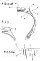
- Figs.5 (a) and (b) provided tyres having shoulder grooves C extending radially inwardly from the tread edge portions A to the shoulder portion B so that the heat accumulating power of the shoulder portion B is diminished and heat radiation therefrom is promoted.
- an object of the present invention to provide a pneumatic tyre, in which an excessive rise in the temperature of the rubber in the shoulder portions and uneven wear of the tread are effectively prevented to extend the tyre life, and which can facilitate the worn tread removing work in a tyre retreading process.
- a pneumatic tyre having a tread region and a pair of shoulder regions extending radially inwardly one from each edge of the tread region characterised in that each shoulder region is provided with shoulder grooves and buttress hollows, said shoulder grooves being arranged circumferentially of the tyre and extending radially inwardly from the tread edges and terminated at a distance LI radially inwardly from the outer surface of the tread region so that the radially inner ends thereof are located on a circle at the surface of each shoulder region, said buttress hollows being arranged circumferentially of the tyre so as to be positioned one between the circumferentially adjacent two shoulder grooves, and the radially outermost ends of said buttress hollows being located radially inwardly of said radially innermost ends of the shoulder grooves.
- a pneumatic tyre 1 comprises a radial carcass 13 turned up in both edge portions around a pair of bead cores 12, a tread 15 having edges P disposed radially outside the carcass, and a belt 14 disposed between the carcass and the tread and composed of at least two plies of inextensible cords.
- the tread 15 has a pair of shoulder regions 2 located adjacent to the edges P and extending radially inwardly therefrom, a pair of sidewalls situated radially inward of the shoulder regions 2 and a pair of bead regions.
- the distance L1 between the boundary 5 and the outer surface of the tread 15 is usually 0.5 to 4 % of the overall outer diameter of the tyre when new.
- the tyre 1 is provided in the shoulder region 2 with shoulder grooves 6 and buttress hollows 10, thereby defining a buttressed portion 7 on each side of the tyre.
- the buttressed portion 7 is situated radially outwardly of a tyre maximum width point WE.
- the shoulder grooves 6 are spaced in the circumferential direction at regular intervals. However, to reduce the sound pressure level of the pattern noise, they are more preferably arranged at irregular intervals according to a variable pitching method.
- each shoulder groove 6 opens at the outer surface of the tread, and the radially inner end is located at the above-mentioned boundary 5. That is, the shoulder grooves 6 terminate at a distance L1 which is in the range of 0.5 to 4 % of the overall diameter of the tyre when new from the outer surface of the tread 15.
- the width of the shoulder groove 6 is properly set in accordance with the outer diameter of the tyre and the intervals or the pitch's of the shoulder grooves 6.
- each shoulder groove 6 is obliquely formed as shown in Fig. 2 and the corners are rounded off to prevent crack propagation from the repeated deformations during tyre rotations.
- the shoulder grooves 6 may be formed in a triangular shape in cross section as shown in Fig.4.
- each buttress hollow 10 is arranged in the circumferential direction of the tyre so that each buttress hollow 10 is located substantially centrally between two adjacent shoulder grooves 6.
- each buttress hollow 10 is positioned at a distance L3 radially inwards of the boundary 5 which is the position of the radially inner ends 6A of the grooves.
- the distance L3 is in the range of 0.2 to 4 % of the outer diameter of the tyre.
- each shoulder region 2 is provided with a circumferentially continuously extending rib whose outer surface is devoid of any grooves or hollows.
- the rigidity of the resultant buttressed part 17 between adjacent shoulder grooves 6 is large enough to cause partial wear or uneven wear around each buttressed part 17. Further, because the total volume of the rubber used in the thick gauge parts such as the L3 width part or rib and the buttresses Q1 and Q2 is increased. The effect of decreasing the heat generation then becomes less and the distribution of the internal temperature becomes uneven, thereby increasing the internal strain in the buttressed portion 7.
- the buttress hollows 10 are so formed that the maximum groove depth D is 5mm or so, and the length L2 exceeds 0.8% of the outer diameter of the tyre.
- the effect of forming the buttress hollows 10 becomes insufficient for diminishing the heat accumulating power of the shoulder portion 2 and promoting the heat radiation therefrom.
- each buttress hollow 10 is so formed that the bottom 10B thereof is smoothly curved up to the surface of its surrounding.
- the pneumatic tyre according to the present invention is provided in each shoulder region with the buttressed portion 7 so constructed that the shoulder grooves 6 and the buttress hollows 10 are formed alternatively on each side of the circumferentially continuously extending rib. Accordingly, the rubber in the shoulder regions has thick parts and thin parts uniformly, that is, on the whole it has a uniform thickness. As a result, the internal heat generation of the tyre and the difference in rigidity of the rubber can be decreased more evenly in comparison with conventional tyres, which ensures an effective prevention of ply separation and rubber separation at the belt edge.
- the buttress parts 17 between the shoulder grooves 6 are provided with less radial support because the buttress hollows 10 are disposed radially inwardly thereof. Accordingly, the rigidity of such parts does not become much higher than that of the surrounding parts, and as a result, uneven wear such as shoulder wear in which the tread edge portions wear rapidly in comparison with the tread crown portion is effectively prevented.
- the shoulder grooves 6 are so arranged in the circumferential direction of the tyre that their inner ends 6A are brought into a line. Accordingly, when the tread 15 has been worn out and the tyre is put to a retreading process, the inner ends 6A provide the worker with a guide line showing the above mentioned boundary 5 at which the worker must remove the worn tread rubber, which facilitates the worn tread removing work and avoids frequent measuring of the tyre dimensions. This ensures effective reduction in working hours and retreading cost together with an accurately worked tyre and a good external appearance for the retreaded tyre.
Abstract
Description
- The present invention relates to a pneumatic tyre and more particularly to the shoulder regions of a pneumatic tyre.
- It is well known that a tyre is subjected to repeated deformations such as alternating compressive deflection and expansion during rotation and thus heat is generated internally. Especially, in tyres for heavy duty vehicles such as trucks, buses, and so on, the increase in internal temperature is great because of the comparatively thick rubber and the resultant large heat accumulating power thereof. As a result, ply separation failure and/or rubber separation failures are apt to be induced at the belt edge regions by high stress.
- In order to solve such problems the prior art has for example, as shown in Figs.5 (a) and (b) provided tyres having shoulder grooves C extending radially inwardly from the tread edge portions A to the shoulder portion B so that the heat accumulating power of the shoulder portion B is diminished and heat radiation therefrom is promoted.
- However, such tyres have drawbacks including the following:-
- 1. the heat distribution is uneven between the hollow groove parts C and the buttress parts D formed therebetween, which is unfavourable from the point of view of prevention of the above-mentioned separation failures: and
- 2. the resultant high rigidity of the buttress region D tends to cause uneven wear.
- On the other hand, from the point of view of saving resources and/or cost reduction, it is often the case that a worn tyre is retreaded and reused.
- In the above-mentioned prior art tyres, however, it is also hard to determine the position for the boundary G which defines the worn portion to be removed, and frequent measuring work is required therefor. Accordingly, the work of removing a worn tread E from a base tyre T (base body) in a retreading process becomes difficult and the retreading cost is therefore increased. Furthermore, in sticking a new tread onto the base tyre, it is necessary to join precisely the shoulder grooves C, but often gaps or differences are formed in the joint, which makes for a bad external appearance.
- Therefore, to avoid such problems it is obvious to remove the rubber of the shoulder regions in which the shoulder grooves C are formed together with worn tread rubber as shown in Fig.5 (a) by the chain line L, but this work inevitably still further increases the amount of rubber to be removed, and lowers the working efficiency. It is, therefore, an object of the present invention to provide a pneumatic tyre, in which an excessive rise in the temperature of the rubber in the shoulder portions and uneven wear of the tread are effectively prevented to extend the tyre life, and which can facilitate the worn tread removing work in a tyre retreading process.
- A pneumatic tyre having a tread region and a pair of shoulder regions extending radially inwardly one from each edge of the tread region characterised in that each shoulder region is provided with shoulder grooves and buttress hollows, said shoulder grooves being arranged circumferentially of the tyre and extending radially inwardly from the tread edges and terminated at a distance LI radially inwardly from the outer surface of the tread region so that the radially inner ends thereof are located on a circle at the surface of each shoulder region, said buttress hollows being arranged circumferentially of the tyre so as to be positioned one between the circumferentially adjacent two shoulder grooves, and the radially outermost ends of said buttress hollows being located radially inwardly of said radially innermost ends of the shoulder grooves.
- Further features will become apparent from the following description of a radial tyre for heavy duty vehicles by way of example only with reference to the accompanying drawings, in which:
- Fig.1 is a half sectional view of a tyre
- Fig.2 is a plan view showing the tread region of the tyre
- Fig.3 is a partial side view showing the buttressed part of the shoulder region
- Fig.4. is a sectional view showing another example of the shoulder groove in the present invention; and
- Figs.5 (a) and (b) are a plan view and a side view respectively of a conventional tyre.
- In the drawings, a pneumatic tyre 1 comprises a
radial carcass 13 turned up in both edge portions around a pair of bead cores 12, atread 15 having edges P disposed radially outside the carcass, and abelt 14 disposed between the carcass and the tread and composed of at least two plies of inextensible cords. - The
tread 15 has a pair of shoulder regions 2 located adjacent to the edges P and extending radially inwardly therefrom, a pair of sidewalls situated radially inward of the shoulder regions 2 and a pair of bead regions. - As shown particularly in Figs 1 & 3 by an
imaginary line 5 between thebelt layer 14 and the base oftread grooves 16 there is a boundary between thebase tyre 1A to be used for the main body tread part to be removed. The distance L1 between theboundary 5 and the outer surface of thetread 15 is usually 0.5 to 4 % of the overall outer diameter of the tyre when new. - The tyre 1 is provided in the shoulder region 2 with
shoulder grooves 6 andbuttress hollows 10, thereby defining a buttressed portion 7 on each side of the tyre. The buttressed portion 7 is situated radially outwardly of a tyre maximum width point WE. - The
shoulder grooves 6 are spaced in the circumferential direction at regular intervals. However, to reduce the sound pressure level of the pattern noise, they are more preferably arranged at irregular intervals according to a variable pitching method. - The radially
outer end 6B of eachshoulder groove 6 opens at the outer surface of the tread, and the radially inner end is located at the above-mentionedboundary 5. That is, theshoulder grooves 6 terminate at a distance L1 which is in the range of 0.5 to 4 % of the overall diameter of the tyre when new from the outer surface of thetread 15. - The width of the
shoulder groove 6 is properly set in accordance with the outer diameter of the tyre and the intervals or the pitch's of theshoulder grooves 6. - The sidewalls of each
shoulder groove 6 are obliquely formed as shown in Fig. 2 and the corners are rounded off to prevent crack propagation from the repeated deformations during tyre rotations. theshoulder grooves 6 may be formed in a triangular shape in cross section as shown in Fig.4. - The above mentioned
buttress hollows 10 are arranged in the circumferential direction of the tyre so that each buttress hollow 10 is located substantially centrally between twoadjacent shoulder grooves 6. - The radially
outer end 10A of each buttress hollow 10 is positioned at a distance L3 radially inwards of theboundary 5 which is the position of the radiallyinner ends 6A of the grooves. The distance L3 is in the range of 0.2 to 4 % of the outer diameter of the tyre. - Thus the tyre is provided in each shoulder region 2 with a circumferentially continuously extending rib whose outer surface is devoid of any grooves or hollows.
- If the distance L3 is greater than 4 % of the tyre outer diameter, the rigidity of the resultant
buttressed part 17 betweenadjacent shoulder grooves 6 is large enough to cause partial wear or uneven wear around eachbuttressed part 17. Further, because the total volume of the rubber used in the thick gauge parts such as the L3 width part or rib and the buttresses Q1 and Q2 is increased. The effect of decreasing the heat generation then becomes less and the distribution of the internal temperature becomes uneven, thereby increasing the internal strain in the buttressed portion 7. - Preferably, the
buttress hollows 10 are so formed that the maximum groove depth D is 5mm or so, and the length L2 exceeds 0.8% of the outer diameter of the tyre. - If the length L2 is less than 0.8% of the tyre outer diameter, the effect of forming the
buttress hollows 10 becomes insufficient for diminishing the heat accumulating power of the shoulder portion 2 and promoting the heat radiation therefrom. - If the maximum groove depth D exceeds 5mm, the strength of the tyre becomes too low.
- In order to diminish the difference in rigidity between the hollowed
parts 10 and the buttressed parts Q2 and to alleviate strain, preferably each buttress hollow 10 is so formed that thebottom 10B thereof is smoothly curved up to the surface of its surrounding. - As described above, the pneumatic tyre according to the present invention is provided in each shoulder region with the buttressed portion 7 so constructed that the
shoulder grooves 6 and thebuttress hollows 10 are formed alternatively on each side of the circumferentially continuously extending rib. Accordingly, the rubber in the shoulder regions has thick parts and thin parts uniformly, that is, on the whole it has a uniform thickness. As a result, the internal heat generation of the tyre and the difference in rigidity of the rubber can be decreased more evenly in comparison with conventional tyres, which ensures an effective prevention of ply separation and rubber separation at the belt edge. - Furthermore, the
buttress parts 17 between theshoulder grooves 6 are provided with less radial support because thebuttress hollows 10 are disposed radially inwardly thereof. Accordingly, the rigidity of such parts does not become much higher than that of the surrounding parts, and as a result, uneven wear such as shoulder wear in which the tread edge portions wear rapidly in comparison with the tread crown portion is effectively prevented. - Then again, according to the present invention, the
shoulder grooves 6 are so arranged in the circumferential direction of the tyre that theirinner ends 6A are brought into a line. Accordingly, when thetread 15 has been worn out and the tyre is put to a retreading process, theinner ends 6A provide the worker with a guide line showing the above mentionedboundary 5 at which the worker must remove the worn tread rubber, which facilitates the worn tread removing work and avoids frequent measuring of the tyre dimensions. This ensures effective reduction in working hours and retreading cost together with an accurately worked tyre and a good external appearance for the retreaded tyre.
Claims (4)
Applications Claiming Priority (2)
| Application Number | Priority Date | Filing Date | Title |
|---|---|---|---|
| JP62304072A JPH01145206A (en) | 1987-11-30 | 1987-11-30 | Pneumatic tyre |
| JP304072/87 | 1987-11-30 |
Publications (3)
| Publication Number | Publication Date |
|---|---|
| EP0320143A2 true EP0320143A2 (en) | 1989-06-14 |
| EP0320143A3 EP0320143A3 (en) | 1989-12-13 |
| EP0320143B1 EP0320143B1 (en) | 1992-05-13 |
Family
ID=17928691
Family Applications (1)
| Application Number | Title | Priority Date | Filing Date |
|---|---|---|---|
| EP88311062A Expired EP0320143B1 (en) | 1987-11-30 | 1988-11-23 | Pneumatic tyre |
Country Status (4)
| Country | Link |
|---|---|
| EP (1) | EP0320143B1 (en) |
| JP (1) | JPH01145206A (en) |
| DE (1) | DE3871098D1 (en) |
| MY (1) | MY103480A (en) |
Cited By (9)
| Publication number | Priority date | Publication date | Assignee | Title |
|---|---|---|---|---|
| EP0726174A1 (en) * | 1995-02-13 | 1996-08-14 | Sumitomo Rubber Industries Limited | Pneumatic tyre and method of making the same |
| WO2001038109A1 (en) * | 1999-11-24 | 2001-05-31 | The Goodyear Tire & Rubber Company | A method of molding a tire and mold therefor |
| US6564839B1 (en) * | 2000-11-01 | 2003-05-20 | The Goodyear Tire & Rubber Company | Pneumatic tire having a load dependent adaptive footprint shape |
| US6955782B1 (en) | 1999-11-24 | 2005-10-18 | The Goodyear Tire & Rubber Company | Method of molding a tire and mold therefor |
| US7341082B2 (en) * | 2004-12-28 | 2008-03-11 | The Goodyear Tire & Rubber Company | Shoulder ribs for pneumatic tires |
| CN101890883A (en) * | 2009-05-18 | 2010-11-24 | 东洋橡胶工业株式会社 | Air-inflation tyre |
| JP2014076765A (en) * | 2012-10-11 | 2014-05-01 | Yokohama Rubber Co Ltd:The | Retreaded tire |
| CN104718088B (en) * | 2012-10-10 | 2017-03-08 | 横滨橡胶株式会社 | Pneumatic tire |
| CN111479704A (en) * | 2017-12-12 | 2020-07-31 | 株式会社普利司通 | Heavy load tire |
Families Citing this family (5)
| Publication number | Priority date | Publication date | Assignee | Title |
|---|---|---|---|---|
| JPH0331007A (en) * | 1989-06-28 | 1991-02-08 | Sumitomo Rubber Ind Ltd | Pneumatic tire |
| JPH04238703A (en) * | 1991-01-10 | 1992-08-26 | Sumitomo Rubber Ind Ltd | Pneumatic tire |
| JP5667410B2 (en) * | 2010-10-19 | 2015-02-12 | 住友ゴム工業株式会社 | Pneumatic radial tire |
| JP5830861B2 (en) * | 2011-01-07 | 2015-12-09 | 横浜ゴム株式会社 | Tire regeneration method and buffing device for tire regeneration |
| JP6959850B2 (en) * | 2017-12-12 | 2021-11-05 | 株式会社ブリヂストン | Heavy load tires |
Citations (5)
| Publication number | Priority date | Publication date | Assignee | Title |
|---|---|---|---|---|
| FR863821A (en) * | 1940-03-04 | 1941-04-10 | Seiberling Rubber Co | Improvements to pneumatic envelopes |
| GB746479A (en) * | 1953-02-03 | 1956-03-14 | Dunlop Rubber Co | Improvements in pneumatic tyres |
| US4222424A (en) * | 1977-12-28 | 1980-09-16 | Bridgestone Tire Company Limited | Lug tires with uniform base rubber gauge |
| USRE30549E (en) * | 1978-10-23 | 1981-03-24 | Uniroyal, Inc. | Pneumatic tire |
| EP0072500A2 (en) * | 1981-08-17 | 1983-02-23 | Bayer Ag | Pneumatic tyre for heavy loads |
-
1987
- 1987-11-30 JP JP62304072A patent/JPH01145206A/en active Granted
-
1988
- 1988-11-18 MY MYPI88001312A patent/MY103480A/en unknown
- 1988-11-23 DE DE8888311062T patent/DE3871098D1/en not_active Expired - Fee Related
- 1988-11-23 EP EP88311062A patent/EP0320143B1/en not_active Expired
Patent Citations (5)
| Publication number | Priority date | Publication date | Assignee | Title |
|---|---|---|---|---|
| FR863821A (en) * | 1940-03-04 | 1941-04-10 | Seiberling Rubber Co | Improvements to pneumatic envelopes |
| GB746479A (en) * | 1953-02-03 | 1956-03-14 | Dunlop Rubber Co | Improvements in pneumatic tyres |
| US4222424A (en) * | 1977-12-28 | 1980-09-16 | Bridgestone Tire Company Limited | Lug tires with uniform base rubber gauge |
| USRE30549E (en) * | 1978-10-23 | 1981-03-24 | Uniroyal, Inc. | Pneumatic tire |
| EP0072500A2 (en) * | 1981-08-17 | 1983-02-23 | Bayer Ag | Pneumatic tyre for heavy loads |
Cited By (11)
| Publication number | Priority date | Publication date | Assignee | Title |
|---|---|---|---|---|
| EP0726174A1 (en) * | 1995-02-13 | 1996-08-14 | Sumitomo Rubber Industries Limited | Pneumatic tyre and method of making the same |
| WO2001038109A1 (en) * | 1999-11-24 | 2001-05-31 | The Goodyear Tire & Rubber Company | A method of molding a tire and mold therefor |
| US6955782B1 (en) | 1999-11-24 | 2005-10-18 | The Goodyear Tire & Rubber Company | Method of molding a tire and mold therefor |
| US6564839B1 (en) * | 2000-11-01 | 2003-05-20 | The Goodyear Tire & Rubber Company | Pneumatic tire having a load dependent adaptive footprint shape |
| US7341082B2 (en) * | 2004-12-28 | 2008-03-11 | The Goodyear Tire & Rubber Company | Shoulder ribs for pneumatic tires |
| CN101890883A (en) * | 2009-05-18 | 2010-11-24 | 东洋橡胶工业株式会社 | Air-inflation tyre |
| US8534336B2 (en) | 2009-05-18 | 2013-09-17 | Toyo Tire & Rubber Co., Ltd. | Pneumatic tire |
| CN101890883B (en) * | 2009-05-18 | 2014-09-03 | 东洋橡胶工业株式会社 | Pneumatic tire |
| CN104718088B (en) * | 2012-10-10 | 2017-03-08 | 横滨橡胶株式会社 | Pneumatic tire |
| JP2014076765A (en) * | 2012-10-11 | 2014-05-01 | Yokohama Rubber Co Ltd:The | Retreaded tire |
| CN111479704A (en) * | 2017-12-12 | 2020-07-31 | 株式会社普利司通 | Heavy load tire |
Also Published As
| Publication number | Publication date |
|---|---|
| EP0320143A3 (en) | 1989-12-13 |
| JPH0581442B2 (en) | 1993-11-12 |
| EP0320143B1 (en) | 1992-05-13 |
| DE3871098D1 (en) | 1992-06-17 |
| JPH01145206A (en) | 1989-06-07 |
| MY103480A (en) | 1993-06-30 |
Similar Documents
| Publication | Publication Date | Title |
|---|---|---|
| EP0320143B1 (en) | Pneumatic tyre | |
| EP0726174B1 (en) | Pneumatic tyre and method of making the same | |
| JP5322610B2 (en) | Pneumatic tire and method for manufacturing pneumatic tire | |
| EP0246995B1 (en) | Tire treads | |
| US5277727A (en) | Contoured replacement tread | |
| EP2022615B1 (en) | Mold for vulcanization of a tire and pneumatic tire vulcanized by use of the mold | |
| US4305446A (en) | Cast tire and method of manufacture | |
| JP5667433B2 (en) | Tire vulcanization mold and method for manufacturing pneumatic tire | |
| EP0413574B1 (en) | High speed radial tyre | |
| US3198234A (en) | Method of repairing pneumatic tires and patches therefor | |
| US5151139A (en) | Heavy duty radial tire having durable buttress portion | |
| EP1400375B1 (en) | A truck steer tire, a mold and a method of molding | |
| JP4017218B2 (en) | Aircraft pneumatic tire | |
| JPH11151909A (en) | Pneumatic tire for heavy load | |
| JPH05185808A (en) | Radial tire for construction vehicle | |
| JP3210421B2 (en) | Manufacturing method of pneumatic radial tire | |
| JPH0338407A (en) | Precure tread | |
| JP2004098953A (en) | Pneumatic tire for recapping, recapping method, and recapped tire | |
| JP2007030310A (en) | Nozzle for extruding rubber member for tread and extruder | |
| JP4333822B2 (en) | Tires for heavy vehicles | |
| JPH1148714A (en) | Pneumatic tire | |
| JP4714354B2 (en) | Heavy duty radial tire | |
| JPH02133202A (en) | Pneumatic tire for heavy load | |
| JPH08216621A (en) | Retreaded tire | |
| JPH10217717A (en) | Pneumatic radial tire for heavy load |
Legal Events
| Date | Code | Title | Description |
|---|---|---|---|
| PUAI | Public reference made under article 153(3) epc to a published international application that has entered the european phase |
Free format text: ORIGINAL CODE: 0009012 |
|
| AK | Designated contracting states |
Kind code of ref document: A2 Designated state(s): DE FR GB |
|
| PUAL | Search report despatched |
Free format text: ORIGINAL CODE: 0009013 |
|
| AK | Designated contracting states |
Kind code of ref document: A3 Designated state(s): DE FR GB |
|
| 17P | Request for examination filed |
Effective date: 19900403 |
|
| 17Q | First examination report despatched |
Effective date: 19910925 |
|
| GRAA | (expected) grant |
Free format text: ORIGINAL CODE: 0009210 |
|
| AK | Designated contracting states |
Kind code of ref document: B1 Designated state(s): DE FR GB |
|
| REF | Corresponds to: |
Ref document number: 3871098 Country of ref document: DE Date of ref document: 19920617 |
|
| ET | Fr: translation filed | ||
| PLBE | No opposition filed within time limit |
Free format text: ORIGINAL CODE: 0009261 |
|
| STAA | Information on the status of an ep patent application or granted ep patent |
Free format text: STATUS: NO OPPOSITION FILED WITHIN TIME LIMIT |
|
| 26N | No opposition filed | ||
| PGFP | Annual fee paid to national office [announced via postgrant information from national office to epo] |
Ref country code: FR Payment date: 20011113 Year of fee payment: 14 |
|
| PGFP | Annual fee paid to national office [announced via postgrant information from national office to epo] |
Ref country code: GB Payment date: 20011121 Year of fee payment: 14 |
|
| PGFP | Annual fee paid to national office [announced via postgrant information from national office to epo] |
Ref country code: DE Payment date: 20011210 Year of fee payment: 14 |
|
| REG | Reference to a national code |
Ref country code: GB Ref legal event code: IF02 |
|
| PG25 | Lapsed in a contracting state [announced via postgrant information from national office to epo] |
Ref country code: GB Free format text: LAPSE BECAUSE OF NON-PAYMENT OF DUE FEES Effective date: 20021123 |
|
| PG25 | Lapsed in a contracting state [announced via postgrant information from national office to epo] |
Ref country code: DE Free format text: LAPSE BECAUSE OF NON-PAYMENT OF DUE FEES Effective date: 20030603 |
|
| GBPC | Gb: european patent ceased through non-payment of renewal fee | ||
| PG25 | Lapsed in a contracting state [announced via postgrant information from national office to epo] |
Ref country code: FR Free format text: LAPSE BECAUSE OF NON-PAYMENT OF DUE FEES Effective date: 20030731 |
|
| REG | Reference to a national code |
Ref country code: FR Ref legal event code: ST |