EP0319087A2 - Improved structural shape made from a substantially rigid material, for refrigerator cabinets and the like, provided with a tight-sealing gasket made from a substantially soft material - Google Patents
Improved structural shape made from a substantially rigid material, for refrigerator cabinets and the like, provided with a tight-sealing gasket made from a substantially soft material Download PDFInfo
- Publication number
- EP0319087A2 EP0319087A2 EP88202688A EP88202688A EP0319087A2 EP 0319087 A2 EP0319087 A2 EP 0319087A2 EP 88202688 A EP88202688 A EP 88202688A EP 88202688 A EP88202688 A EP 88202688A EP 0319087 A2 EP0319087 A2 EP 0319087A2
- Authority
- EP
- European Patent Office
- Prior art keywords
- structural shape
- door
- counter
- gasket
- shape according
- Prior art date
- Legal status (The legal status is an assumption and is not a legal conclusion. Google has not performed a legal analysis and makes no representation as to the accuracy of the status listed.)
- Withdrawn
Links
Images

Classifications
-
- F—MECHANICAL ENGINEERING; LIGHTING; HEATING; WEAPONS; BLASTING
- F25—REFRIGERATION OR COOLING; COMBINED HEATING AND REFRIGERATION SYSTEMS; HEAT PUMP SYSTEMS; MANUFACTURE OR STORAGE OF ICE; LIQUEFACTION SOLIDIFICATION OF GASES
- F25D—REFRIGERATORS; COLD ROOMS; ICE-BOXES; COOLING OR FREEZING APPARATUS NOT OTHERWISE PROVIDED FOR
- F25D23/00—General constructional features
- F25D23/08—Parts formed wholly or mainly of plastics materials
- F25D23/082—Strips
-
- E—FIXED CONSTRUCTIONS
- E06—DOORS, WINDOWS, SHUTTERS, OR ROLLER BLINDS IN GENERAL; LADDERS
- E06B—FIXED OR MOVABLE CLOSURES FOR OPENINGS IN BUILDINGS, VEHICLES, FENCES OR LIKE ENCLOSURES IN GENERAL, e.g. DOORS, WINDOWS, BLINDS, GATES
- E06B7/00—Special arrangements or measures in connection with doors or windows
- E06B7/16—Sealing arrangements on wings or parts co-operating with the wings
- E06B7/22—Sealing arrangements on wings or parts co-operating with the wings by means of elastic edgings, e.g. elastic rubber tubes; by means of resilient edgings, e.g. felt or plush strips, resilient metal strips
- E06B7/23—Plastic, sponge rubber, or like strips or tubes
- E06B7/2314—Plastic, sponge rubber, or like strips or tubes characterised by the material
Definitions
- European patent application Nr. 84201887 to the same owner discloses a structural shape made from a substantially rigid plastic material for refrigertaor cabinets, or the like, wherein the door of the cabinet comprises a counter-door, with said structural shape bearing a bellows-like acting gasket made from a substantially less rigid material, which accomplishes a tight sealing between the door and the cabinet, with the structural shape and the gasket being suitably coupled with each other, or manufactured as one single piece by means of the co-extrusion of said materials of different stiffness, so as to make it possible the gasket, which is less rigid, to be quickly detached from the structural shape, whichs is more rigid, along the region of their mutual connection.
- the structural shape is provided, on its side destined to be placed in a position opposite to the cabinet when in use, with two flat faces between which a groove is defined, which is suitable for receiving a spare gasket
- the structural shape is provided, along at least one of its sides, with an elastically yielding side flange, which acts as a spring in order to provide a snap-coupling with the counter-door, during the step of components assemblage.
- the object of the present invention is substantially an improvement of the structural shape as disclosed in said European patent application.
- a first purpose of the present invention is to improve in a decidedly advantageous way the structure of the spring which is used in order to fasten the structural shape to the counter-door.
- structural shapes known from the prior art totally made from a rigid material, it is of basic importance to obtain a very good elasticity of the spring, which must yield under the pressure applied by the counter-door during the assemblage step, and then elastically return - once that said pressure is relieved - to spring-like lock the edge of said counter-door.
- the present invention proposes a structural shape made from a substantially rigid material for refrigerator cabinets and the like, in which the door of the cabinet comprises a counter-door, with said structural shape bearing a tubular bellows-like gasket made from a substantially soft material, which accomplished a tight sealing between the door and the case of said cabinet, with the structural shape and the gasket being suitably coupled with each other, or manufactured as one single piece by means of the co-extrusion of said substantially rigid and said substantially soft materials, with said structural shape being provided with at least one side, elastically yielding flange which acts as a spring in order to accomplish a snap-coupling with the counter-door during the step of components assemblage, characterized in that in said side flange the fulcrum of the spring is constituted by an elbow-shaped insert of said substantially soft material fabricated inside the substantially rigid material the structural shape is made from.
- the structural shape is made, e.g., from rigid PVC; the gasket, the insert of the structural shape which acts as the fulcrum of the spring, and the other soft parts are made from soft, plasticized PVC.
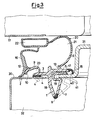
- a structural shape 1 has a complex cross-section, which on its side which, in its operating position ( Figure 3), is opposite to the case 17 of a refrigerator cabinet, has two faces 3 and 5 substantially planar an extending on mutually staggered planes.
- the face 5 and with a side tight-sealing stripe 15, and the face 3 is provided with a tight-sealing stripe 4, with both of said stripes being made from a soft material, co-extruded with the rigid material of the structural shape.
- the cross-section of the structural shape 1 takes an irregular-"T" shape due to the effect of a rib 18 which extends verifically in the direction opposite to the direction towards the cabinet 17, assuming a configuration slightly bent outwards.
- a side flange 7 extends in the direction of the face 5, with said side flange 7 being elastically yielding as a spring around a fulcrum 8, which is constituted by an elbow-shaped insert made from a soft material co-extruded with the rigid material which constitutes the structural shape.
- the side flange 7 ends with a groove-shaped configuration 19, having a "C"-shaped cross-section ending with a tooth 41 suitable for getting engaged with the counter-door.
- a flange 9 extends laterally, with said flange 9 being directed otwards and inclined towards the door of the cabinet.
- a flange 9 ends with a tooth 10.
- a groove 23 is thus defined.
- the structural shape 1 is made from a rigid plastic material, e.g., PVC, fabricated by extrusion, cut and welded in correspondence of the corners, so to form a frame which reproduces the perimetrical outline of the door of the refrigerator cabinet onto which it has to be applied.
- PVC polyvinyl styrene
- the gasket 20 has a tubular cross-section which defines a chamber 21 acting as a bellows, and a seat 22 suitable for receiving a bar of a magnetic material.
- the inner side wall, indicated by the reference numeral 6, of the gasket 20, is bonded to the face 5 of the structural shape in correspondence of the co-extrusion region 13, and the external side wall, indicated by the reference numeral 16, is bonded to the side flange 9 of the structural shape along a junction region 12.
- the configuration of the lower portion of the external side wall 16 of the gasket (a wall which can be suitably differentiated into two regions of different thickness, or of different stiffness, in order to give lateral stability to the same wall), is characteristic according to the herein exemplified form of practical embodiment of the present invention: in fact, the wall 16 extends downwards beyond the region 12 of junction with the structural shape, ending with a foot 2 which comes to rest against the counter-door when the parts are assembled in their operating position, so as render the structural shape 1 not any longer visible in such a position.
- the tight-sealing stripes 4 and 15 represent gaskets for containing the material foamed during the foaming operation which is carried out at the end of the assemblage step, in order to endow the door with heat-insulating characteristics.
- the stripe 15 is so made, as to provide a tight sealing, compensating for the distance between the face 5 of the structural shape and the counter-door 31, between which an air gap 40 is defined, in order to leave a free room for the elastic return of the tooth 41 of the side flange 7, and make easier the movement of engagement of said tooth on the counter-door.
- the tight-sealing stripe 15 serves to facilitate such a movement of the side flange 7, because it preserves the distance between the face 5 of the structural shape and the counter-door 31, leaving a free clearance for the tooth 41 to move inside the air gap 40.
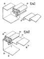
- the structural shape 1 bearing the gasket 18 is suitably prearranged in a frame shape, and in this form is it supplied to the manufacturer of the refrigerator cabinet; as Figures 1 and 2 schematically show, said manufacturer can assemble, in one operation only, the door 30 of steel sheet with the counter-door 31 of plastic material, by snapwise (spring-like) inserting the structural shape 1, which gets interlocked with the counter-door thanks to the action of the side flange 7, which behaves as a spring.
- the structural shape 1 is made move downwards, e.g , by means of a suitable mechanical arm, towards the counter-door 31, e.g , suitably positioned on a support which keeps it blocked.
- the arm of the side flange 7, in the initial position shown in Figure 1, and shown in chain in Figure 3 comes into contact with the edge of the counter-door 31, by being urged by the thrust applied by this latter yields and starts elastically bending inwards, as a spring, around he fulcrum 8, which is considerably flexible.
- the so-assembled structural shape 1 and the counter-door 31 are then leant on the door 30, and the whole is blocked by carrying out the foaming inside the air gap 32.
- FIG. 4 shows, when the soft co-extruded gasket 20 deteriorates due to wear, a rapid replacement can be carried out by tearing it off along the regions 12 and 13 of junction with the structural shape, and inserting a new gasket 33 inside the groove 23.
- a spare gasket of soft PVC is characterzied by a base 34 from whose external side end a vertical foot 35 extends. From the end of this latter foot, a wedge-shaped foot 11 of co-extruded rigid PVC, ending with a tooth 14, extends in the direction of the groove 23 of the structural shape.
- the gasket 33 is inserted laterally by causing the rigid wedge 11 to slide along the door 30, and pushing. In this way, under the thrust applied by the wedge, the flange 9 elastically opens wide by a short distance receiving the tooth 14, which, by stopping against the tooth 10 of the structural shape, fastens the spare gasket in its position.
- the advantages and the improvements which can be obtained with the structural shape according to the instant invention are many: first of all, the accomplishment of the spring which snapwise engages the counter-door - with the fulcrum being constituted by a co-extruded insert made from a soft material - makes it possible a high flexibility of said spring to be attained, with no need for its thickness to be reduced and measured with precision.
- the elbow-shaped insert makes it possible approximately the same flexibility of the spring to be obtained, which one would have in a structural shape entirely consisting of a rigid material in case the fulcrum thickness of this latter was approximately equal to half of the thickness of the insert according to the present invention.
- a further advantage of the present invention is accomplished, according to a form of practical embodiment thereof, thanks to the extended structure of the external side wall of the bellows of the gasket which - as seen - comes to rest against the counter-door, so as to render not any longer visible the flat face of the rigid structural shape.
- the rigid structural shape (see Figures 3 and 4) remains completely hidden when is assembled on the refrigerator, it can be suitably manufactured from a non-coloured material, with a strong reduction in the added costs, and in production scraps
- a further advantage derives from the operation of replacement of the original gasket with the spare gasket, which can be obtained thanks to the herein exemplified form of practical embodiment of the sructural shape.
- the insertion of the spare gasket takes place laterally in the purposely provided external groove with which the structural shape is provided.
- a groove remains hence in a free and accessible position, ideal for being able to receive, during the manufacturing step, a male element acting as a gauge for maintaining constant its shape, as well as its distance from the door plane.
- Such a feature is very useful in order to make it possible said groove - which must receive the rigid interlocking wedge the spare gasket is provided with - to be correctly and constantly dimensioned, preventing any risks that difficulties may be met when this latter is inserted, in case the groove is too narrow, or an excessive backlash exists, in case the groove is too wide.
Landscapes
- Engineering & Computer Science (AREA)
- Chemical & Material Sciences (AREA)
- Combustion & Propulsion (AREA)
- Physics & Mathematics (AREA)
- Mechanical Engineering (AREA)
- Thermal Sciences (AREA)
- General Engineering & Computer Science (AREA)
- Civil Engineering (AREA)
- Structural Engineering (AREA)
- Refrigerator Housings (AREA)
- Gasket Seals (AREA)
- Specific Sealing Or Ventilating Devices For Doors And Windows (AREA)
Abstract
Description
- European patent application Nr. 84201887 to the same owner, discloses a structural shape made from a substantially rigid plastic material for refrigertaor cabinets, or the like, wherein the door of the cabinet comprises a counter-door, with said structural shape bearing a bellows-like acting gasket made from a substantially less rigid material, which accomplishes a tight sealing between the door and the cabinet, with the structural shape and the gasket being suitably coupled with each other, or manufactured as one single piece by means of the co-extrusion of said materials of different stiffness, so as to make it possible the gasket, which is less rigid, to be quickly detached from the structural shape, whichs is more rigid, along the region of their mutual connection.
- According to said European patent application, the structural shape is provided, on its side destined to be placed in a position opposite to the cabinet when in use, with two flat faces between which a groove is defined, which is suitable for receiving a spare gasket The structural shape is provided, along at least one of its sides, with an elastically yielding side flange, which acts as a spring in order to provide a snap-coupling with the counter-door, during the step of components assemblage.
- The object of the present invention is substantially an improvement of the structural shape as disclosed in said European patent application.
- In particular, a first purpose of the present invention is to improve in a decidedly advantageous way the structure of the spring which is used in order to fasten the structural shape to the counter-door. In fact, it is well known that in the hereinabove briefly mentioned structural shapes known from the prior art, totally made from a rigid material, it is of basic importance to obtain a very good elasticity of the spring, which must yield under the pressure applied by the counter-door during the assemblage step, and then elastically return - once that said pressure is relieved - to spring-like lock the edge of said counter-door. In order to obtain these characteristics, it is necessary to give the structural shape a suitably thin thickness in its region of the fulcrum of the spring.
- However, during the manufacturing of the components, which takes place by extrusion through a die, such a thickness of the structural shape in that critical region can begin to vary, and, in particular, to increase, owing to a progressive wear of the die caused by the friction of the material flowing inside it. An increase in the thickness of the structural shape of even some fractions of a tenth of a millimiter can cause a loss in spring elasticity, and therefore problems during the assemblage step, in particular if the counter-door has a low thickness, because in that case the spring may not adequately yield under the thrust applied by said counter-door Therefore, in order to continue to obtain with precision, and constant, the prefixed shape and thickness of the structural shape, a periodical and careful maintenance of the die is necessary.
- In order to solve this problem, and achieve further advantages as regards both the production and the use of the structural shape in question, advantages which will be clear from a reading of the following disclosure, the present invention proposes a structural shape made from a substantially rigid material for refrigerator cabinets and the like, in which the door of the cabinet comprises a counter-door, with said structural shape bearing a tubular bellows-like gasket made from a substantially soft material, which accomplished a tight sealing between the door and the case of said cabinet, with the structural shape and the gasket being suitably coupled with each other, or manufactured as one single piece by means of the co-extrusion of said substantially rigid and said substantially soft materials, with said structural shape being provided with at least one side, elastically yielding flange which acts as a spring in order to accomplish a snap-coupling with the counter-door during the step of components assemblage, characterized in that in said side flange the fulcrum of the spring is constituted by an elbow-shaped insert of said substantially soft material fabricated inside the substantially rigid material the structural shape is made from.
- The structural shape is made, e.g., from rigid PVC; the gasket, the insert of the structural shape which acts as the fulcrum of the spring, and the other soft parts are made from soft, plasticized PVC.
- In order to better understand the characteristics and the advantages of the present invention, hereinunder an example of non-limitative practical embodiment thereof is disclosed, by referring to the figures of the hereto attached drawings.
- Figure 1 shows a perspective view of a structural shape according to the invention in combination with the other components it is destined to cooperate with, before the assemblage.
- Figure 2 shows a view similar to that of Figure 1, after that the assemblage is carried out.
- Figure 3 shows a sectional view along the path III-III of Figure 2.
- Figure 4 shows a sectional view similar to that of Figure 3, wherein the original gasket is replaced by a spare gasket.
- Referring to the figures, a
structural shape 1 according to the present invention has a complex cross-section, which on its side which, in its operating position (Figure 3), is opposite to thecase 17 of a refrigerator cabinet, has twofaces face 5 and with a side tight-sealing stripe 15, and theface 3 is provided with a tight-sealing stripe 4, with both of said stripes being made from a soft material, co-extruded with the rigid material of the structural shape. In an intermediate position between thefaces structural shape 1 takes an irregular-"T" shape due to the effect of arib 18 which extends verifically in the direction opposite to the direction towards thecabinet 17, assuming a configuration slightly bent outwards. From the end of saidrib 18, a side flange 7 extends in the direction of theface 5, with said side flange 7 being elastically yielding as a spring around afulcrum 8, which is constituted by an elbow-shaped insert made from a soft material co-extruded with the rigid material which constitutes the structural shape. - The side flange 7 ends with a groove-
shaped configuration 19, having a "C"-shaped cross-section ending with atooth 41 suitable for getting engaged with the counter-door. - On the opposite side of the structural shape, i.e , that structural shape side which is opposite, in the operating position, to the cabinet, from the face 3 a
flange 9 extends laterally, with saidflange 9 being directed otwards and inclined towards the door of the cabinet. Such aflange 9 ends with atooth 10. Between theface 3, theflange 9 and thetooth 10, agroove 23 is thus defined. - The
structural shape 1 is made from a rigid plastic material, e.g., PVC, fabricated by extrusion, cut and welded in correspondence of the corners, so to form a frame which reproduces the perimetrical outline of the door of the refrigerator cabinet onto which it has to be applied. - Together, and as an enbloc, with the
structural shape 1, also agasket 20, of soft plasticized PVC, is fabricated by co-estrusion - The
gasket 20 has a tubular cross-section which defines achamber 21 acting as a bellows, and aseat 22 suitable for receiving a bar of a magnetic material. The inner side wall, indicated by the reference numeral 6, of thegasket 20, is bonded to theface 5 of the structural shape in correspondence of theco-extrusion region 13, and the external side wall, indicated by thereference numeral 16, is bonded to theside flange 9 of the structural shape along ajunction region 12. The configuration of the lower portion of theexternal side wall 16 of the gasket (a wall which can be suitably differentiated into two regions of different thickness, or of different stiffness, in order to give lateral stability to the same wall), is characteristic according to the herein exemplified form of practical embodiment of the present invention: in fact, thewall 16 extends downwards beyond theregion 12 of junction with the structural shape, ending with afoot 2 which comes to rest against the counter-door when the parts are assembled in their operating position, so as render thestructural shape 1 not any longer visible in such a position. - The tight-
sealing stripes stripe 15 is so made, as to provide a tight sealing, compensating for the distance between theface 5 of the structural shape and thecounter-door 31, between which anair gap 40 is defined, in order to leave a free room for the elastic return of thetooth 41 of the side flange 7, and make easier the movement of engagement of said tooth on the counter-door. - The tight-
sealing stripe 15 serves to facilitate such a movement of the side flange 7, because it preserves the distance between theface 5 of the structural shape and thecounter-door 31, leaving a free clearance for thetooth 41 to move inside theair gap 40. - In the example shown in the Figures, in this case the mutual alignment of the door and of the counter-door in their end positions, at the end of the assemblage, is secured by the positioning of the
faces air gap 40 on the inner side of the structural shape is compensated for by the position at a lower height of theface 3 relatively to theface 5. However, in general it is not necessary that the door and the counter-door are positioned at a same level. - For the installation, the
structural shape 1 bearing thegasket 18 is suitably prearranged in a frame shape, and in this form is it supplied to the manufacturer of the refrigerator cabinet; as Figures 1 and 2 schematically show, said manufacturer can assemble, in one operation only, thedoor 30 of steel sheet with thecounter-door 31 of plastic material, by snapwise (spring-like) inserting thestructural shape 1, which gets interlocked with the counter-door thanks to the action of the side flange 7, which behaves as a spring. - The
structural shape 1 is made move downwards, e.g , by means of a suitable mechanical arm, towards thecounter-door 31, e.g , suitably positioned on a support which keeps it blocked. As soon as the arm of the side flange 7, in the initial position shown in Figure 1, and shown in chain in Figure 3, comes into contact with the edge of thecounter-door 31, by being urged by the thrust applied by this latter yields and starts elastically bending inwards, as a spring, around he fulcrum 8, which is considerably flexible. When the stroke of the yielding arm of the side flange 7 along the edge of thecounter-door 31 is ended, and this latter has come to the level of thegroove 19, the flange 7 goes off owing to the effect of its elastic return, and engages the edge of thecounter-door 31, locking it. - The so-assembled
structural shape 1 and thecounter-door 31 are then leant on thedoor 30, and the whole is blocked by carrying out the foaming inside theair gap 32. - As Figure 4 shows, when the
soft co-extruded gasket 20 deteriorates due to wear, a rapid replacement can be carried out by tearing it off along theregions new gasket 33 inside thegroove 23. Such a spare gasket of soft PVC is characterzied by abase 34 from whose external side end avertical foot 35 extends. From the end of this latter foot, a wedge-shaped foot 11 of co-extruded rigid PVC, ending with atooth 14, extends in the direction of thegroove 23 of the structural shape. For the replacement, from the initial position shown in chain in Figure 4, thegasket 33 is inserted laterally by causing therigid wedge 11 to slide along thedoor 30, and pushing. In this way, under the thrust applied by the wedge, theflange 9 elastically opens wide by a short distance receiving thetooth 14, which, by stopping against thetooth 10 of the structural shape, fastens the spare gasket in its position. - In general, the advantages and the improvements which can be obtained with the structural shape according to the instant invention are many: first of all, the accomplishment of the spring which snapwise engages the counter-door - with the fulcrum being constituted by a co-extruded insert made from a soft material - makes it possible a high flexibility of said spring to be attained, with no need for its thickness to be reduced and measured with precision.
- In fact, the elbow-shaped insert makes it possible approximately the same flexibility of the spring to be obtained, which one would have in a structural shape entirely consisting of a rigid material in case the fulcrum thickness of this latter was approximately equal to half of the thickness of the insert according to the present invention.
- Therefore, the very advantageous result is obtained, that a high thickness can be maintained in the structural shape in that critical region, without it being necessary said thickness to be constantly monitored owing to the wear of the die, which, in fact, in case of present invention, does not have any appreciable influence on the flexibility of the spring. Furthermore, having the possibility of maintaining high the value of the thickness of the bending region of the spring means a higher mechanical strength of the component.
- A further advantage of the present invention is accomplished, according to a form of practical embodiment thereof, thanks to the extended structure of the external side wall of the bellows of the gasket which - as seen - comes to rest against the counter-door, so as to render not any longer visible the flat face of the rigid structural shape.
- This is an advantage, in that it is rather difficult to succeed in obtaining the same colour shade in the rigid structural shape, and in the soft gasket. Different colour shades visible in the assembled structural shapes are rejected by the users, and are therefore a cause of scrap in production
- Inasmuch as, according to the above mentioned form of practical embodiment of the present invention, the rigid structural shape (see Figures 3 and 4) remains completely hidden when is assembled on the refrigerator, it can be suitably manufactured from a non-coloured material, with a strong reduction in the added costs, and in production scraps
- In such case, the changes in colour will only affect the gasket, which remains he only component in view after the end of the assemblage.
- A further advantage derives from the operation of replacement of the original gasket with the spare gasket, which can be obtained thanks to the herein exemplified form of practical embodiment of the sructural shape.
- In fact, the insertion of the spare gasket takes place laterally in the purposely provided external groove with which the structural shape is provided. Such a groove remains hence in a free and accessible position, ideal for being able to receive, during the manufacturing step, a male element acting as a gauge for maintaining constant its shape, as well as its distance from the door plane. Such a feature is very useful in order to make it possible said groove - which must receive the rigid interlocking wedge the spare gasket is provided with - to be correctly and constantly dimensioned, preventing any risks that difficulties may be met when this latter is inserted, in case the groove is too narrow, or an excessive backlash exists, in case the groove is too wide.
Claims (10)
Applications Claiming Priority (2)
| Application Number | Priority Date | Filing Date | Title |
|---|---|---|---|
| IT2289587 | 1987-12-04 | ||
| IT22895/87A IT1223221B (en) | 1987-12-04 | 1987-12-04 | PROFILE IMPROVED IN SUBSTANTIALLY RIGID MATERIAL, FOR REFRIGERATOR AND SIMILAR FURNITURE, EQUIPPED WITH A SEALING GASKET IN SUBSTANTIALLY SOFT MATERIAL |
Publications (2)
| Publication Number | Publication Date |
|---|---|
| EP0319087A2 true EP0319087A2 (en) | 1989-06-07 |
| EP0319087A3 EP0319087A3 (en) | 1990-04-25 |
Family
ID=11201641
Family Applications (1)
| Application Number | Title | Priority Date | Filing Date |
|---|---|---|---|
| EP88202688A Withdrawn EP0319087A3 (en) | 1987-12-04 | 1988-11-25 | Improved structural shape made from a substantially rigid material, for refrigerator cabinets and the like, provided with a tight-sealing gasket made from a substantially soft material |
Country Status (6)
| Country | Link |
|---|---|
| EP (1) | EP0319087A3 (en) |
| JP (1) | JPH0528460Y2 (en) |
| DE (1) | DE319087T1 (en) |
| DK (1) | DK672888A (en) |
| IT (1) | IT1223221B (en) |
| YU (1) | YU47296B (en) |
Cited By (24)
| Publication number | Priority date | Publication date | Assignee | Title |
|---|---|---|---|---|
| EP0559267A3 (en) * | 1992-03-05 | 1993-12-08 | Ilpea Ind Spa | Gasket in particular for internal doors |
| WO1994006993A1 (en) * | 1992-09-22 | 1994-03-31 | Universal Technologies Pty., Ltd. | Panel with compressible edge member |
| DE29511425U1 (en) * | 1995-07-14 | 1995-11-09 | Liebherr-Hausgeräte GmbH, 88416 Ochsenhausen | Profile for sealing a door or flap against a carcass part |
| DE29619300U1 (en) * | 1996-11-07 | 1996-12-19 | REHAU AG + Co., 95111 Rehau | Profile for sealing a door |
| EP0713067A3 (en) * | 1994-11-18 | 1997-07-09 | Bs Electrodomesticos Sa | Improved refrigerator seal |
| EP0905464A1 (en) * | 1997-09-30 | 1999-03-31 | Industrie Ilpea S.P.A. | Plastic material profile having a rigid deformable base for refrigerators |
| US5916076A (en) * | 1996-01-15 | 1999-06-29 | Industrie Ilpea S.P.A. | Plastics structural shape for refrigerator cabinets |
| EP0959312A3 (en) * | 1998-05-18 | 2000-02-02 | Liebherr-Hausgeräte Gmbh | Profile for sealing a door or a shutter against a body part |
| WO2000028267A1 (en) | 1998-11-05 | 2000-05-18 | Industrie Ilpea S.P.A. | Gasket for refrigerators with a profiled outer door |
| DE19907147A1 (en) * | 1999-02-19 | 2000-08-24 | Bsh Bosch Siemens Hausgeraete | Refrigerator door has inner cladding formed out of metallic material, out of high quality steel bar in non-cutting fashion, as far as possible |
| WO2002063227A1 (en) | 2001-02-02 | 2002-08-15 | Industrie Ilpea S.P.A. | Profile in particular for refrigerator furniture units |
| WO2002066912A1 (en) | 2001-02-02 | 2002-08-29 | Industrie Ilpea S.P.A. | Method and apparatus for assembling in an automated manner a sealing profile on an inner door for refrigerators |
| WO2002070971A1 (en) | 2001-03-07 | 2002-09-12 | Industrie Ilpea S.P.A. | Improved sealing assembly for refrigerator cabinets and the like with a profile made of plastic material |
| WO2003048662A1 (en) | 2001-12-04 | 2003-06-12 | Industrie Ilpea S.P.A. | Seal for refrigerator furniture units and the like, able in particular to compensate for manufacturing tolerances |
| WO2003052334A1 (en) | 2001-12-18 | 2003-06-26 | Rehau Ltd | An improved gasket |
| WO2006079650A1 (en) | 2005-01-28 | 2006-08-03 | Industrie Ilpea S.P.A. | Gasket for refrigerator cabinets with high heat insulation properties |
| WO2012076509A1 (en) | 2010-12-10 | 2012-06-14 | Industrie Ilpea S.P.A. | Magnetic gasket for refrigerator cabinets |
| US8240091B2 (en) | 2005-03-21 | 2012-08-14 | Industrie Ilpea S.P.A. | Double-seal gasket for refrigerator cabinets with high heat insulation properties |
| EP2843334A1 (en) | 2013-08-28 | 2015-03-04 | Electrolux Appliances Aktiebolag | Gasket for heat insulated cabinets |
| WO2017108190A1 (en) * | 2015-12-23 | 2017-06-29 | Rehau Ag + Co | Profiled arrangement, particularly for a refrigerator and/or freezer device |
| WO2017108189A1 (en) * | 2015-12-23 | 2017-06-29 | Rehau Ag + Co | Refrigerator and/or freezer device |
| US9841223B2 (en) | 2014-12-01 | 2017-12-12 | Samsung Electronics Co., Ltd. | Refrigerator |
| CN111713795A (en) * | 2020-07-21 | 2020-09-29 | 北京英华高科技环保有限公司 | A New Antivirus Smart Helmet |
| EP3569757B1 (en) | 2018-05-16 | 2022-08-03 | BSH Hausgeräte GmbH | Door of a household appliance with a sealing element having a closure element in the form of a ring section |
Family Cites Families (7)
| Publication number | Priority date | Publication date | Assignee | Title |
|---|---|---|---|---|
| US3378956A (en) * | 1965-02-23 | 1968-04-23 | Goodrich Co B F | Extruded sealing member |
| GB1240441A (en) * | 1970-01-02 | 1971-07-21 | Ford Motor Co | Weatherstrip |
| US4305230A (en) * | 1979-12-19 | 1981-12-15 | Jarrow Products, Inc. | Sealing retainer |
| DE3022381A1 (en) * | 1980-06-14 | 1981-12-24 | Licentia Patent-Verwaltungs-Gmbh, 6000 Frankfurt | Profile seal for e.g. refrigerator door - has seal foot rigid relative to seal head material and divided between sections |
| EP0146994B1 (en) * | 1983-12-23 | 1989-01-25 | ILPEA S.p.A. | Profile of plastic material for refrigerator cabinets |
| FR2566723A1 (en) * | 1984-06-27 | 1986-01-03 | Mesnel Sa Ets | Motor vehicle bodywork seal, originally tipping and thus with a double function |
| IT8522093V0 (en) * | 1985-06-05 | 1985-06-05 | Ilpea Spa | COMPOUND PROFILE IN PLASTIC MATERIAL FOR FURNITURE, REFRIGERATOR SPECIES, WITH DOOR AND COUNTER DOOR FIXED BY SCREWS AND WITH GASKET FIXED TO THE PROFILE. |
-
1987
- 1987-12-04 IT IT22895/87A patent/IT1223221B/en active
-
1988
- 1988-11-25 EP EP88202688A patent/EP0319087A3/en not_active Withdrawn
- 1988-11-25 DE DE198888202688T patent/DE319087T1/en active Pending
- 1988-12-02 YU YU219988A patent/YU47296B/en unknown
- 1988-12-02 DK DK672888A patent/DK672888A/en not_active Application Discontinuation
- 1988-12-05 JP JP1988158453U patent/JPH0528460Y2/ja not_active Expired - Lifetime
Cited By (32)
| Publication number | Priority date | Publication date | Assignee | Title |
|---|---|---|---|---|
| EP0559267A3 (en) * | 1992-03-05 | 1993-12-08 | Ilpea Ind Spa | Gasket in particular for internal doors |
| WO1994006993A1 (en) * | 1992-09-22 | 1994-03-31 | Universal Technologies Pty., Ltd. | Panel with compressible edge member |
| EP0713067A3 (en) * | 1994-11-18 | 1997-07-09 | Bs Electrodomesticos Sa | Improved refrigerator seal |
| DE29511425U1 (en) * | 1995-07-14 | 1995-11-09 | Liebherr-Hausgeräte GmbH, 88416 Ochsenhausen | Profile for sealing a door or flap against a carcass part |
| US5916076A (en) * | 1996-01-15 | 1999-06-29 | Industrie Ilpea S.P.A. | Plastics structural shape for refrigerator cabinets |
| DE29619300U1 (en) * | 1996-11-07 | 1996-12-19 | REHAU AG + Co., 95111 Rehau | Profile for sealing a door |
| RU2210704C2 (en) * | 1997-09-30 | 2003-08-20 | Индустрие Ильпеа С.п.А. | Plastic section with corrugated lining |
| EP0905464A1 (en) * | 1997-09-30 | 1999-03-31 | Industrie Ilpea S.P.A. | Plastic material profile having a rigid deformable base for refrigerators |
| US6058657A (en) * | 1997-09-30 | 2000-05-09 | Industrie Ilpea S.P.A. | Plastic material profile for refrigerators having a rigid deformable base |
| EP0959312A3 (en) * | 1998-05-18 | 2000-02-02 | Liebherr-Hausgeräte Gmbh | Profile for sealing a door or a shutter against a body part |
| WO2000028267A1 (en) | 1998-11-05 | 2000-05-18 | Industrie Ilpea S.P.A. | Gasket for refrigerators with a profiled outer door |
| DE19907147A1 (en) * | 1999-02-19 | 2000-08-24 | Bsh Bosch Siemens Hausgeraete | Refrigerator door has inner cladding formed out of metallic material, out of high quality steel bar in non-cutting fashion, as far as possible |
| WO2002066912A1 (en) | 2001-02-02 | 2002-08-29 | Industrie Ilpea S.P.A. | Method and apparatus for assembling in an automated manner a sealing profile on an inner door for refrigerators |
| WO2002063227A1 (en) | 2001-02-02 | 2002-08-15 | Industrie Ilpea S.P.A. | Profile in particular for refrigerator furniture units |
| US6785948B2 (en) | 2001-02-02 | 2004-09-07 | Industrie Ilpea S.P.A. | Method and apparatus for assembling in an automated manner a sealing profile on an inner door for refrigerators |
| US7080485B2 (en) | 2001-02-02 | 2006-07-25 | Industrie Ilpea S.P.A. | Gasket for refrigerator furniture units |
| WO2002070971A1 (en) | 2001-03-07 | 2002-09-12 | Industrie Ilpea S.P.A. | Improved sealing assembly for refrigerator cabinets and the like with a profile made of plastic material |
| US7219471B2 (en) * | 2001-03-07 | 2007-05-22 | Industrie Ilpea S.P.A. | Refrigerator cabinet sealing assembly having a bellows-seal gasket |
| WO2003048662A1 (en) | 2001-12-04 | 2003-06-12 | Industrie Ilpea S.P.A. | Seal for refrigerator furniture units and the like, able in particular to compensate for manufacturing tolerances |
| WO2003052334A1 (en) | 2001-12-18 | 2003-06-26 | Rehau Ltd | An improved gasket |
| WO2006079650A1 (en) | 2005-01-28 | 2006-08-03 | Industrie Ilpea S.P.A. | Gasket for refrigerator cabinets with high heat insulation properties |
| US8104228B2 (en) | 2005-01-28 | 2012-01-31 | Industrie Ilpea S.P.A. | Gasket for refrigerator cabinets with high heat insulation properties |
| US8240091B2 (en) | 2005-03-21 | 2012-08-14 | Industrie Ilpea S.P.A. | Double-seal gasket for refrigerator cabinets with high heat insulation properties |
| WO2012076509A1 (en) | 2010-12-10 | 2012-06-14 | Industrie Ilpea S.P.A. | Magnetic gasket for refrigerator cabinets |
| US9121635B2 (en) | 2010-12-10 | 2015-09-01 | Industrie Ilpea S.P.A. | Magnetic gasket for refrigerator cabinets |
| EP2843334A1 (en) | 2013-08-28 | 2015-03-04 | Electrolux Appliances Aktiebolag | Gasket for heat insulated cabinets |
| US9841223B2 (en) | 2014-12-01 | 2017-12-12 | Samsung Electronics Co., Ltd. | Refrigerator |
| WO2017108190A1 (en) * | 2015-12-23 | 2017-06-29 | Rehau Ag + Co | Profiled arrangement, particularly for a refrigerator and/or freezer device |
| WO2017108189A1 (en) * | 2015-12-23 | 2017-06-29 | Rehau Ag + Co | Refrigerator and/or freezer device |
| US11098525B2 (en) | 2015-12-23 | 2021-08-24 | Rehau Ag + Co. | Profiled arrangement, particularly for a refrigerator and/or freezer device |
| EP3569757B1 (en) | 2018-05-16 | 2022-08-03 | BSH Hausgeräte GmbH | Door of a household appliance with a sealing element having a closure element in the form of a ring section |
| CN111713795A (en) * | 2020-07-21 | 2020-09-29 | 北京英华高科技环保有限公司 | A New Antivirus Smart Helmet |
Also Published As
| Publication number | Publication date |
|---|---|
| DE319087T1 (en) | 1989-12-07 |
| DK672888D0 (en) | 1988-12-02 |
| JPH0528460Y2 (en) | 1993-07-21 |
| IT8722895A0 (en) | 1987-12-04 |
| DK672888A (en) | 1989-06-05 |
| YU219988A (en) | 1992-07-20 |
| IT1223221B (en) | 1990-09-19 |
| EP0319087A3 (en) | 1990-04-25 |
| YU47296B (en) | 1995-01-31 |
| JPH0191881U (en) | 1989-06-16 |
Similar Documents
| Publication | Publication Date | Title |
|---|---|---|
| EP0319087A2 (en) | Improved structural shape made from a substantially rigid material, for refrigerator cabinets and the like, provided with a tight-sealing gasket made from a substantially soft material | |
| US4411401A (en) | Headrail mounting bracket | |
| US3411247A (en) | Refrigerator door frame | |
| US5584526A (en) | Fixedly installable window pane for motor vehicles | |
| US7219471B2 (en) | Refrigerator cabinet sealing assembly having a bellows-seal gasket | |
| US5743047A (en) | Seal for simultaneously sealing a door window pane and a door opening on a motor vehicle | |
| CA1051485A (en) | Trim molding assembly | |
| US5364180A (en) | Drawer side wall formed of an upper double-walled profile section and a bottom profile section inserted into the open bottom of the upper profile section | |
| US5916076A (en) | Plastics structural shape for refrigerator cabinets | |
| US5095657A (en) | Door seal | |
| ITMI982406A1 (en) | GASKET FOR FROGORIFERI WITH SHAPED COUNTERPORT. | |
| US3333364A (en) | Lined window guide channel | |
| PL187051B1 (en) | Shape in particular that of plastic material | |
| EP0416899A1 (en) | Strip structure for automotive vehicles | |
| US5890784A (en) | Drawer slide | |
| US4454687A (en) | Guide and support assembly for a window pane | |
| UA78200C2 (en) | Improved profile, in particular for refrigerator furniture units | |
| CA1212973A (en) | Window arrangement having a pane which is adjustable in height, particularly for motor vehicles | |
| US3126589A (en) | Monti | |
| US4512045A (en) | Structural assembly, for shower partition or the like | |
| KR0167594B1 (en) | Plastic holder for fixing the support strip for glass plates or filling plates to the frame of a window or door | |
| US2549315A (en) | Windshield mounting | |
| US2983969A (en) | Building construction | |
| US3359686A (en) | Window glass channel | |
| US2757422A (en) | Door jamb sealing strip |
Legal Events
| Date | Code | Title | Description |
|---|---|---|---|
| PUAI | Public reference made under article 153(3) epc to a published international application that has entered the european phase |
Free format text: ORIGINAL CODE: 0009012 |
|
| AK | Designated contracting states |
Kind code of ref document: A2 Designated state(s): AT BE CH DE ES FR GB GR IT LI LU NL SE |
|
| DET | De: translation of patent claims | ||
| PUAL | Search report despatched |
Free format text: ORIGINAL CODE: 0009013 |
|
| AK | Designated contracting states |
Kind code of ref document: A3 Designated state(s): AT BE CH DE ES FR GB GR IT LI LU NL SE |
|
| 17P | Request for examination filed |
Effective date: 19900917 |
|
| 17Q | First examination report despatched |
Effective date: 19910425 |
|
| STAA | Information on the status of an ep patent application or granted ep patent |
Free format text: STATUS: THE APPLICATION IS DEEMED TO BE WITHDRAWN |
|
| 18D | Application deemed to be withdrawn |
Effective date: 19920505 |