EP0319038A2 - Sealing structure of an electrostrictive element - Google Patents
Sealing structure of an electrostrictive element Download PDFInfo
- Publication number
- EP0319038A2 EP0319038A2 EP88120173A EP88120173A EP0319038A2 EP 0319038 A2 EP0319038 A2 EP 0319038A2 EP 88120173 A EP88120173 A EP 88120173A EP 88120173 A EP88120173 A EP 88120173A EP 0319038 A2 EP0319038 A2 EP 0319038A2
- Authority
- EP
- European Patent Office
- Prior art keywords
- electrostrictive element
- tubular member
- electrostrictive
- lid
- members
- Prior art date
- Legal status (The legal status is an assumption and is not a legal conclusion. Google has not performed a legal analysis and makes no representation as to the accuracy of the status listed.)
- Granted
Links
Images

Classifications
-
- H—ELECTRICITY
- H10—SEMICONDUCTOR DEVICES; ELECTRIC SOLID-STATE DEVICES NOT OTHERWISE PROVIDED FOR
- H10N—ELECTRIC SOLID-STATE DEVICES NOT OTHERWISE PROVIDED FOR
- H10N30/00—Piezoelectric or electrostrictive devices
- H10N30/80—Constructional details
- H10N30/88—Mounts; Supports; Enclosures; Casings
- H10N30/883—Further insulation means against electrical, physical or chemical damage, e.g. protective coatings
-
- H—ELECTRICITY
- H10—SEMICONDUCTOR DEVICES; ELECTRIC SOLID-STATE DEVICES NOT OTHERWISE PROVIDED FOR
- H10N—ELECTRIC SOLID-STATE DEVICES NOT OTHERWISE PROVIDED FOR
- H10N30/00—Piezoelectric or electrostrictive devices
- H10N30/50—Piezoelectric or electrostrictive devices having a stacked or multilayer structure
Definitions
- Piezoelectric actuators have been regarded as a promising mechanical driving element for optical or magnetic disc heads, various optical devices and precision positioning devices for precision tool machines. Since the mechanical displacement caused by electrostrictive effect is essentially very small, the rectangular piezoelectric effect is usually increased by stacking a plurality of electrostrictive ceramic layers or piezoelectric ceramic layers with internal electrodes as is disclosed in the U.S. Patent No. 4,681,667 issued on July 21, 1987. The mechanical displacement may be further increased by using a mechanical amplification mechanism as is disclosed in the U.S. Patent No. 4,570,095 issued on February 11, 1986.
- the sealing structure of the electrostrictive element has a pair of lid members mounted on both ends of the electrostrictive element.
- the electrostrictive element is inserted within a tubular member such that the side surfaces of the lid members are partially covered with the end portion of the tubular member and connected to each other to form flexible sealing joint portions so as to prevent moisture from entering into the tubular member from outside while allowing a small displacement in a direction of the tubular axis.
- One of lid members has a pair of lead terminals which are connected to external electrodes of the electrostrictive element via lead wires. It is preferable that the tubular member and the lid members are made of metal to enhance the reliability, and elastic sealing material is used to combine the metal tube and the metal lids so as to ease the mechanical displacement of the electrostrictive element.
- an electrostrictive element assembly of this embodiment comprises an electrostrictive element 1 housed within a tubular member 14 and sealed with a first lid member or a terminal member 11 and a second lid member 13 by using elastic sealing resine 15.
- the terminal member 11 has lead terminals rods 41 and 42 connected to the electrostrictive element 1.
- the electrostrictive element 1 in this embodiment is a sintered body which is described in the aforementioned U.S. Patent No. 4,681,667. Exposed ends of internal electrodes 5 on side faces of the electrostrictive element 1, are coated selectively with an inorganic insulator 6 such as glass. Then a pair of external electrodes 21 and 22 are formed on side faces thereof such that the internal electrodes 5 are alternately connected to the external electrodes 21 and 22 to form two group of comb-shaped electrode members. Subsequently, the lead wires 31 and 32 are connected to the external electrodes 21 and 22 by soldering 7, respectively.
- the electrostrictive element 1 is fixed to a terminal member 11 and a lid member 13 with adhesive material to be supported within the tubular member 14 as shown in FIG. 1.
- the terminal member 11 is a circular disc which has a pair of holes provided with lead terminal rods 41 and 42.
- the lead terminal rods 41 and 42 are supported by sealing glass 43 and then realed from the atmosphere.
- Each lead wires 31 and 32 are connected with ends of a lead terminal rods 41 and 42 by soldering, respectively.
- the terminal member 11 and the lid member 13 have the same diameter which is smaller than the internal diameter of the tubular member 14 but larger enough such that the electrostrictive element 1 is spaced apart from the inner wall of the tubular member 14.
- the terminal member 11 and the lid member 13 are flexibly and air-tightly combined to the tubular member 14 by using elastic sealing material such as silicone resin and epoxy resin for air-tightness. As shown in FIG.
- the tubular member has a hight larger than that of the electrostrictive element 1 but less than the total sum of the terminal member 11, the lid member and the electrostrictive element 1.
- the materials of the terminal member 11 and the lid member 13 are preferably metals, especially stainless steel.
- the electrostrictive element assembly thus prepared was tested for 1,000 hours at 40°C, and 90 - 95%RH, and applied with a DC voltage of 150 V. The test showed no adverse results.
- each electrostrictive sheet 9 between internal electrodes When a voltage is applied via the lead terminal rods 41 and 42 from a voltage supply source (not shown) between the external electrodes 21 and 22, all the electrostrictive sheets 9 between internal electrodes are applied with voltage to generate electrostrictive strain in the element in a direction of axis of the tubular member 14.
- the thickness of each electrostrictive sheet is 0.1 mm and stacked with 770 sheets, the displacement of about 0.1 mm can be obtained. For such a small displacement, the elastic resin can keep the air-tightness.
- FIG. 2 shows another embodiment. This embodiment differs from the first embodiment in that an O-ring 16 is used as the elasting sealing means.
- the terminal member 11 and the lid member 13 are provided with grooves so that the O-ring 16 is flexibly attached to the members 11 and 13.
- the size of the grooves is determined such that the compression ratio of the O-ring 16 becomes 0.85 - 0.65.
- the O-ring 16 which is applied with silicone grease is fitted in each groove, and a stainless steel tube 14 of the thickness of 0.5 mm is forced in from one direction.
- the electrostrictive element assembly thus completed was tested under the same conditions as in the first embodiment, but no adverse result was observed.
- FIG. 3 shows the third embodiment of this invention.
- the third embodiment differs from the first embodiment shown in FIG. 1 only in that insulation liquid 8 is filled within the tubular member 14. More specifically, on an end face of the electrostrictive element 1 is fixed a disc-shaped metal member 11 made of stainless steel which is provided with a pair of lead terminals 41 and 42 connected to the external electrodes 21 and 22 via lead wires 31 and 32, respectively. On the other end face of the electrostrictive element 1 is fixed a disc-shaped metal member 13 having the outer diameter identical to that of the metal member 11. The joint portions between the tubular member 14 and the metal members 11 and 13 are sealed by epoxy resin 15. The side faces of the electrostrictive element are spaced apart from the inner wall of the stainless steel tube 14 of 0.5 mm in thickness, and silicone oil 8 is filled within the tube 14.
- multicomponent solid solution ceramic powder of a perovskite structure is mixed with an organic binder to prepare green-sheets of about 100 ⁇ m in thickness, which is coated with silver internal electrode conductive layers in paste form. After dried, thus coated sheets are stacked for lamination in several tens of layers (e.g. 72 layers) and sintered to obtain a sintered body. As ends of the silver internal electrode conductive layers are exposed on side faces of the sintered body, end faces are selectively coated with glass insulator. Thus, external electrodes are formed on side faces and connected to the silver internal electrodes alternately in every two layers to form two groups of comb-shaped internal electrode assembly. Lead wires are connected to the external electrodes by soldering for leading out.
- the electrostrictive element 1 thus made is sealed within the tube 14 with the silicone oil 8 after being attached with metal members 11 and 13.
- the electrostrictive element thus prepared was tested under the same conditions as in the first embodiment, but no adverse result was observed.
- FIG. 4 shows the fourth embodiment of the present invention.
- the fourth embodiment differs from the embodiment shown in FIG. 2 only in that silicone oil is filled within the tubular member 14. As other features and structures are the same with the one shown in FIG. 2, detailed description is omitted.
- the insulating liquid to be filled within the tube may be fluorocarbon-based oils or mineral oils.
- this invention can prevent moisture from entering from outside into an electrostrictive element without preventing the mechanical displacement caused by the electrostrictive element in the tube element.
- the tubular member is filled with insulating liquid, the electrical reliability of the electrostrictive element is further improved.
Abstract
Description
- This invention relates to an electrostrictive device such as a piezoelectric actuator, and more particularly to the electrostrictive device having a sealing structure of an electrostrictive element.
- Piezoelectric actuators have been regarded as a promising mechanical driving element for optical or magnetic disc heads, various optical devices and precision positioning devices for precision tool machines. Since the mechanical displacement caused by electrostrictive effect is essentially very small, the rectangular piezoelectric effect is usually increased by stacking a plurality of electrostrictive ceramic layers or piezoelectric ceramic layers with internal electrodes as is disclosed in the U.S. Patent No. 4,681,667 issued on July 21, 1987. The mechanical displacement may be further increased by using a mechanical amplification mechanism as is disclosed in the U.S. Patent No. 4,570,095 issued on February 11, 1986.
- In a conventional electrostrictive element using silver based internal electrodes, migration easily takes place at exposed ends of the internal electrodes in a humid atmosphere, and thus causing a poor insulation characteristics. When moisture resistance tests are conducted, discharge occurs at sides or corners of the electrostrictive element to present serious problems in yielding and reliability. There has been proposed a measurement to coat the electrostrictive element with an insulation resin so as to prevent moisture from entering, but the moisture resistance achieved is not quite satisfactory. In addition, the mechanical displacement of expantion and contraction of the electrostrictive element is impaired by the resin coated on the side surface of the electrostrictive element.
- An object of this invention is to provide an electrostrictive device having a sealing structure for an electrostrictive element which can prevent moisture from entering from outside and remarkably enhance reliability of the electrostrictive element without impairing the mechanical displacement of the electrostrictive element.
- According to this invention, the sealing structure of the electrostrictive element has a pair of lid members mounted on both ends of the electrostrictive element. The electrostrictive element is inserted within a tubular member such that the side surfaces of the lid members are partially covered with the end portion of the tubular member and connected to each other to form flexible sealing joint portions so as to prevent moisture from entering into the tubular member from outside while allowing a small displacement in a direction of the tubular axis. One of lid members has a pair of lead terminals which are connected to external electrodes of the electrostrictive element via lead wires. It is preferable that the tubular member and the lid members are made of metal to enhance the reliability, and elastic sealing material is used to combine the metal tube and the metal lids so as to ease the mechanical displacement of the electrostrictive element.
- Another embodiment of the sealing structure for the electrostrictive element according to this invention further comprises insulation liquid filled within the tubular member.
-
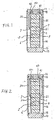
- FIG. 1 shows a sectional view of the first embodiment according to this invention.
- FIG. 2 shows a sectional view of the second embodiment according to this invention.
- FIG. 3 shows a sectional view of the third embodiment according to this invention.
- FIG. 4 shows a sectional view of the fourth embodiment according to this invention.
- Referring to FIG. 1, an electrostrictive element assembly of this embodiment comprises an
electrostrictive element 1 housed within atubular member 14 and sealed with a first lid member or aterminal member 11 and asecond lid member 13 by usingelastic sealing resine 15. Theterminal member 11 haslead terminals rods electrostrictive element 1. - The
electrostrictive element 1 in this embodiment is a sintered body which is described in the aforementioned U.S. Patent No. 4,681,667. Exposed ends ofinternal electrodes 5 on side faces of theelectrostrictive element 1, are coated selectively with an inorganic insulator 6 such as glass. Then a pair ofexternal electrodes internal electrodes 5 are alternately connected to theexternal electrodes lead wires external electrodes electrostrictive element 1 is fixed to aterminal member 11 and alid member 13 with adhesive material to be supported within thetubular member 14 as shown in FIG. 1. Theterminal member 11 is a circular disc which has a pair of holes provided withlead terminal rods lead terminal rods glass 43 and then realed from the atmosphere. Eachlead wires lead terminal rods terminal member 11 and thelid member 13 have the same diameter which is smaller than the internal diameter of thetubular member 14 but larger enough such that theelectrostrictive element 1 is spaced apart from the inner wall of thetubular member 14. Theterminal member 11 and thelid member 13 are flexibly and air-tightly combined to thetubular member 14 by using elastic sealing material such as silicone resin and epoxy resin for air-tightness. As shown in FIG. 1, the tubular member has a hight larger than that of theelectrostrictive element 1 but less than the total sum of theterminal member 11, the lid member and theelectrostrictive element 1. The materials of theterminal member 11 and thelid member 13 are preferably metals, especially stainless steel. As thetubular member 14, a tube of stainless steel of 0.5 mm in thickness is used in this embodiment. - The electrostrictive element assembly thus prepared was tested for 1,000 hours at 40°C, and 90 - 95%RH, and applied with a DC voltage of 150 V. The test showed no adverse results.
- When a voltage is applied via the
lead terminal rods external electrodes electrostrictive sheets 9 between internal electrodes are applied with voltage to generate electrostrictive strain in the element in a direction of axis of thetubular member 14. When the thickness of each electrostrictive sheet is 0.1 mm and stacked with 770 sheets, the displacement of about 0.1 mm can be obtained. For such a small displacement, the elastic resin can keep the air-tightness. - FIG. 2 shows another embodiment. This embodiment differs from the first embodiment in that an O-
ring 16 is used as the elasting sealing means. Theterminal member 11 and thelid member 13 are provided with grooves so that the O-ring 16 is flexibly attached to themembers ring 16 becomes 0.85 - 0.65. The O-ring 16 which is applied with silicone grease is fitted in each groove, and astainless steel tube 14 of the thickness of 0.5 mm is forced in from one direction. Since the displacement of the electrostrictive element is so small, ordinary O-ring can afford to absorb such displacement without causing a slip or slide between the O-ring and the tubular member due to the fact that the value of the displacement of the electrostrictive element does not exceed the elastic displacement region of the rubber used for ordinary O-ring. Therefore, the air-tightness can be sustained. - The electrostrictive element assembly thus completed was tested under the same conditions as in the first embodiment, but no adverse result was observed.
- FIG. 3 shows the third embodiment of this invention. The third embodiment differs from the first embodiment shown in FIG. 1 only in that
insulation liquid 8 is filled within thetubular member 14. More specifically, on an end face of theelectrostrictive element 1 is fixed a disc-shaped metal member 11 made of stainless steel which is provided with a pair oflead terminals external electrodes lead wires electrostrictive element 1 is fixed a disc-shaped metal member 13 having the outer diameter identical to that of themetal member 11. The joint portions between thetubular member 14 and themetal members epoxy resin 15. The side faces of the electrostrictive element are spaced apart from the inner wall of thestainless steel tube 14 of 0.5 mm in thickness, andsilicone oil 8 is filled within thetube 14. - The manufacturing method of the shown electrostrictive element is described below.
- Similarly to the aforementioned U.S. Patent No. 4,681,667, multicomponent solid solution ceramic powder of a perovskite structure is mixed with an organic binder to prepare green-sheets of about 100 µm in thickness, which is coated with silver internal electrode conductive layers in paste form. After dried, thus coated sheets are stacked for lamination in several tens of layers (e.g. 72 layers) and sintered to obtain a sintered body. As ends of the silver internal electrode conductive layers are exposed on side faces of the sintered body, end faces are selectively coated with glass insulator. Thus, external electrodes are formed on side faces and connected to the silver internal electrodes alternately in every two layers to form two groups of comb-shaped internal electrode assembly. Lead wires are connected to the external electrodes by soldering for leading out. The
electrostrictive element 1 thus made is sealed within thetube 14 with thesilicone oil 8 after being attached withmetal members - The electrostrictive element thus prepared was tested under the same conditions as in the first embodiment, but no adverse result was observed.
- FIG. 4 shows the fourth embodiment of the present invention. The fourth embodiment differs from the embodiment shown in FIG. 2 only in that silicone oil is filled within the
tubular member 14. As other features and structures are the same with the one shown in FIG. 2, detailed description is omitted. - Although the silicone oil is used in the foregoing instance, the insulating liquid to be filled within the tube may be fluorocarbon-based oils or mineral oils.
- As described in the foregoing statement, this invention can prevent moisture from entering from outside into an electrostrictive element without preventing the mechanical displacement caused by the electrostrictive element in the tube element. When the tubular member is filled with insulating liquid, the electrical reliability of the electrostrictive element is further improved.
Claims (6)
Applications Claiming Priority (4)
| Application Number | Priority Date | Filing Date | Title |
|---|---|---|---|
| JP306543/87 | 1987-12-02 | ||
| JP62306543A JPH01146379A (en) | 1987-12-02 | 1987-12-02 | Electrostrictive element assembly |
| JP63279773A JPH02125675A (en) | 1988-11-04 | 1988-11-04 | Electrostrictive element |
| JP279773/88 | 1988-11-04 |
Publications (3)
| Publication Number | Publication Date |
|---|---|
| EP0319038A2 true EP0319038A2 (en) | 1989-06-07 |
| EP0319038A3 EP0319038A3 (en) | 1990-08-01 |
| EP0319038B1 EP0319038B1 (en) | 1994-07-13 |
Family
ID=26553483
Family Applications (1)
| Application Number | Title | Priority Date | Filing Date |
|---|---|---|---|
| EP88120173A Expired - Lifetime EP0319038B1 (en) | 1987-12-02 | 1988-12-02 | Sealing structure of an electrostrictive element |
Country Status (2)
| Country | Link |
|---|---|
| EP (1) | EP0319038B1 (en) |
| DE (1) | DE3850641T2 (en) |
Cited By (12)
| Publication number | Priority date | Publication date | Assignee | Title |
|---|---|---|---|---|
| US5059857A (en) * | 1990-09-28 | 1991-10-22 | Caterpillar Inc. | Integral connector for a piezoelectric solid state motor stack |
| US5148077A (en) * | 1990-09-28 | 1992-09-15 | Caterpillar Inc. | Coating surrounding a piezoelectric solid state motor stack |
| US5218259A (en) * | 1992-02-18 | 1993-06-08 | Caterpillar Inc. | Coating surrounding a piezoelectric solid state motor stack |
| EP0613124A2 (en) * | 1993-02-05 | 1994-08-31 | Discovision Associates | Shock-resistant, electrostatically actuated pick-up for optical recording and playback |
| WO1998047188A2 (en) * | 1997-04-14 | 1998-10-22 | Siemens Aktiengesellschaft | Piezoelectric actuator with a hollow profile |
| EP0954037A1 (en) * | 1998-04-22 | 1999-11-03 | Siemens Aktiengesellschaft | Piezoelectric device for an actuator |
| WO2003009400A2 (en) * | 2001-07-12 | 2003-01-30 | Ceramtec Ag Innovative Ceramic Engineering | Monolithic multilayer actuator in a housing |
| US6617766B1 (en) * | 1999-06-19 | 2003-09-09 | Robert Bosch Gmbh | Piezoelectric actuator |
| WO2004047191A2 (en) * | 2002-11-19 | 2004-06-03 | Volkswagen Mechatronic Gmbh & Co. Kg | Piezo actuator contact mechanism for an injection valve and method for producing said actuator |
| WO2005112142A1 (en) * | 2004-05-14 | 2005-11-24 | Siemens Aktiengesellschaft | Head plate assembly for an actuator and method of producing an actuator |
| WO2007122149A1 (en) * | 2006-04-21 | 2007-11-01 | Robert Bosch Gmbh | Piezoelectric actuator module having a sheath, and a method for producing said module |
| DE102010055266A1 (en) * | 2010-12-20 | 2012-06-21 | Epcos Ag | Electrical component i.e. microelectronic component, for creating operation voltage in LCD backlight unit in e.g. laptop, has chip for connecting arms to terminal, where surface of chip is arranged at retention device in non-contact manner |
Citations (2)
| Publication number | Priority date | Publication date | Assignee | Title |
|---|---|---|---|---|
| JPS60128874A (en) * | 1983-12-13 | 1985-07-09 | Nippon Soken Inc | Electrostrictive actuator |
| US4553059A (en) * | 1983-11-10 | 1985-11-12 | Nippon Soken, Inc. | Piezoelectric actuator and a piezoelectric pump injector incorporating the same |
-
1988
- 1988-12-02 DE DE3850641T patent/DE3850641T2/en not_active Expired - Fee Related
- 1988-12-02 EP EP88120173A patent/EP0319038B1/en not_active Expired - Lifetime
Patent Citations (2)
| Publication number | Priority date | Publication date | Assignee | Title |
|---|---|---|---|---|
| US4553059A (en) * | 1983-11-10 | 1985-11-12 | Nippon Soken, Inc. | Piezoelectric actuator and a piezoelectric pump injector incorporating the same |
| JPS60128874A (en) * | 1983-12-13 | 1985-07-09 | Nippon Soken Inc | Electrostrictive actuator |
Non-Patent Citations (1)
| Title |
|---|
| PATENT ABSTRACTS OF JAPAN vol. 9, no. 288 (E-358)(2011) 15 November 1985, & JP-A-60 128874 (NIPPON JIDOSHA BUHIN SOGO KENKYUSHO K.K.) 09 July 1985, * |
Cited By (21)
| Publication number | Priority date | Publication date | Assignee | Title |
|---|---|---|---|---|
| US5148077A (en) * | 1990-09-28 | 1992-09-15 | Caterpillar Inc. | Coating surrounding a piezoelectric solid state motor stack |
| US5059857A (en) * | 1990-09-28 | 1991-10-22 | Caterpillar Inc. | Integral connector for a piezoelectric solid state motor stack |
| US5218259A (en) * | 1992-02-18 | 1993-06-08 | Caterpillar Inc. | Coating surrounding a piezoelectric solid state motor stack |
| EP0613124A2 (en) * | 1993-02-05 | 1994-08-31 | Discovision Associates | Shock-resistant, electrostatically actuated pick-up for optical recording and playback |
| EP0613124A3 (en) * | 1993-02-05 | 1995-01-04 | Discovision Ass | Shock-resistant, electrostatically actuated pick-up for optical recording and playback. |
| US5485437A (en) * | 1993-02-05 | 1996-01-16 | Discovision Associates | Shock-resistant, electrostatically actuated pick-up for optical recording and playback |
| WO1998047188A2 (en) * | 1997-04-14 | 1998-10-22 | Siemens Aktiengesellschaft | Piezoelectric actuator with a hollow profile |
| WO1998047188A3 (en) * | 1997-04-14 | 1999-01-28 | Siemens Ag | Piezoelectric actuator with a hollow profile |
| EP0954037A1 (en) * | 1998-04-22 | 1999-11-03 | Siemens Aktiengesellschaft | Piezoelectric device for an actuator |
| US6274967B1 (en) | 1998-04-22 | 2001-08-14 | Siemens Aktiengesellschaft | Piezoelectric actuator for a servo drive, servo drive with a piezoelectric actuator and method of producing a piezoelectric actuator |
| US6617766B1 (en) * | 1999-06-19 | 2003-09-09 | Robert Bosch Gmbh | Piezoelectric actuator |
| WO2003009400A2 (en) * | 2001-07-12 | 2003-01-30 | Ceramtec Ag Innovative Ceramic Engineering | Monolithic multilayer actuator in a housing |
| WO2003009400A3 (en) * | 2001-07-12 | 2003-11-06 | Ceramtec Ag | Monolithic multilayer actuator in a housing |
| US6943482B2 (en) | 2001-07-12 | 2005-09-13 | Ceramtec Ag Innovative Ceramic Engineering | Monolithic multilayer actuator in a housing |
| WO2004047191A2 (en) * | 2002-11-19 | 2004-06-03 | Volkswagen Mechatronic Gmbh & Co. Kg | Piezo actuator contact mechanism for an injection valve and method for producing said actuator |
| WO2004047191A3 (en) * | 2002-11-19 | 2004-09-23 | Volkswagen Mechatronic Gmbh | Piezo actuator contact mechanism for an injection valve and method for producing said actuator |
| WO2005112142A1 (en) * | 2004-05-14 | 2005-11-24 | Siemens Aktiengesellschaft | Head plate assembly for an actuator and method of producing an actuator |
| US7646139B2 (en) | 2004-05-14 | 2010-01-12 | Siemens Aktiengesellschaft | Head plate assembly for an actuator and method for producing an actuator |
| WO2007122149A1 (en) * | 2006-04-21 | 2007-11-01 | Robert Bosch Gmbh | Piezoelectric actuator module having a sheath, and a method for producing said module |
| US7872398B2 (en) | 2006-04-21 | 2011-01-18 | Robert Bosch Gmbh | Piezoelectric actuator module having a sheath, and a method for its production |
| DE102010055266A1 (en) * | 2010-12-20 | 2012-06-21 | Epcos Ag | Electrical component i.e. microelectronic component, for creating operation voltage in LCD backlight unit in e.g. laptop, has chip for connecting arms to terminal, where surface of chip is arranged at retention device in non-contact manner |
Also Published As
| Publication number | Publication date |
|---|---|
| EP0319038A3 (en) | 1990-08-01 |
| EP0319038B1 (en) | 1994-07-13 |
| DE3850641T2 (en) | 1994-10-27 |
| DE3850641D1 (en) | 1994-08-18 |
Similar Documents
| Publication | Publication Date | Title |
|---|---|---|
| US5113108A (en) | Hermetically sealed electrostrictive actuator | |
| JP2508321B2 (en) | Piezoelectric actuator and manufacturing method thereof | |
| US5153477A (en) | Laminate displacement device | |
| EP0319038A2 (en) | Sealing structure of an electrostrictive element | |
| EP0485995A1 (en) | Laminated piezoelectric actuator | |
| US6668437B1 (en) | Method for producing a stacked piezoelectric element | |
| JPH0457373A (en) | Electrostrictive effect element | |
| JPH04349675A (en) | Piezoelectric actuator | |
| US5144528A (en) | Laminate displacement device | |
| US9478726B2 (en) | Actuator module having a multi-layer actuator arranged in a housing and a continuously extremely low leakage current at the actuator surface | |
| JPS6288382A (en) | Electrostriction effect element | |
| JP3102580B2 (en) | Multilayer piezoelectric actuator | |
| JPS6059981A (en) | Drive device | |
| JPH04352480A (en) | Piezoelectric actuator | |
| JPH02125674A (en) | Electrostrictive element | |
| JPH01146379A (en) | Electrostrictive element assembly | |
| JPH04365384A (en) | Mechanical amplification mechanism | |
| JP2508234B2 (en) | Piezoelectric actuator and manufacturing method thereof | |
| JPH02125675A (en) | Electrostrictive element | |
| JP3010835B2 (en) | Piezo actuator | |
| JPH02250678A (en) | Laminated piezoelectric actuator | |
| JPH02137282A (en) | Electrostriction effect element and its sheathing method | |
| JP2508232B2 (en) | Electrostrictive effect element | |
| JP2536636B2 (en) | Electrostrictive effect element assembly | |
| JPH05206536A (en) | Piezoelectric actuator |
Legal Events
| Date | Code | Title | Description |
|---|---|---|---|
| PUAI | Public reference made under article 153(3) epc to a published international application that has entered the european phase |
Free format text: ORIGINAL CODE: 0009012 |
|
| AK | Designated contracting states |
Kind code of ref document: A2 Designated state(s): DE FR GB |
|
| 17P | Request for examination filed |
Effective date: 19890530 |
|
| PUAL | Search report despatched |
Free format text: ORIGINAL CODE: 0009013 |
|
| AK | Designated contracting states |
Kind code of ref document: A3 Designated state(s): DE FR GB |
|
| RHK1 | Main classification (correction) |
Ipc: H01L 41/04 |
|
| 17Q | First examination report despatched |
Effective date: 19920922 |
|
| GRAA | (expected) grant |
Free format text: ORIGINAL CODE: 0009210 |
|
| AK | Designated contracting states |
Kind code of ref document: B1 Designated state(s): DE FR GB |
|
| PG25 | Lapsed in a contracting state [announced via postgrant information from national office to epo] |
Ref country code: FR Effective date: 19940713 |
|
| REF | Corresponds to: |
Ref document number: 3850641 Country of ref document: DE Date of ref document: 19940818 |
|
| EN | Fr: translation not filed | ||
| PLBE | No opposition filed within time limit |
Free format text: ORIGINAL CODE: 0009261 |
|
| STAA | Information on the status of an ep patent application or granted ep patent |
Free format text: STATUS: NO OPPOSITION FILED WITHIN TIME LIMIT |
|
| 26N | No opposition filed | ||
| PGFP | Annual fee paid to national office [announced via postgrant information from national office to epo] |
Ref country code: GB Payment date: 19981204 Year of fee payment: 11 |
|
| PGFP | Annual fee paid to national office [announced via postgrant information from national office to epo] |
Ref country code: DE Payment date: 19990228 Year of fee payment: 11 |
|
| PG25 | Lapsed in a contracting state [announced via postgrant information from national office to epo] |
Ref country code: GB Free format text: LAPSE BECAUSE OF NON-PAYMENT OF DUE FEES Effective date: 19991202 |
|
| GBPC | Gb: european patent ceased through non-payment of renewal fee |
Effective date: 19991202 |
|
| PG25 | Lapsed in a contracting state [announced via postgrant information from national office to epo] |
Ref country code: DE Free format text: LAPSE BECAUSE OF NON-PAYMENT OF DUE FEES Effective date: 20001003 |