EP0318896A2 - Method for smelting reduction of iron ore and apparatus therefor - Google Patents
Method for smelting reduction of iron ore and apparatus therefor Download PDFInfo
- Publication number
- EP0318896A2 EP0318896A2 EP88119803A EP88119803A EP0318896A2 EP 0318896 A2 EP0318896 A2 EP 0318896A2 EP 88119803 A EP88119803 A EP 88119803A EP 88119803 A EP88119803 A EP 88119803A EP 0318896 A2 EP0318896 A2 EP 0318896A2
- Authority
- EP
- European Patent Office
- Prior art keywords
- gas
- smelting reduction
- reduction furnace
- furnace
- iron ore
- Prior art date
- Legal status (The legal status is an assumption and is not a legal conclusion. Google has not performed a legal analysis and makes no representation as to the accuracy of the status listed.)
- Granted
Links
Images


Classifications
-
- C—CHEMISTRY; METALLURGY
- C21—METALLURGY OF IRON
- C21B—MANUFACTURE OF IRON OR STEEL
- C21B11/00—Making pig-iron other than in blast furnaces
-
- C—CHEMISTRY; METALLURGY
- C21—METALLURGY OF IRON
- C21B—MANUFACTURE OF IRON OR STEEL
- C21B13/00—Making spongy iron or liquid steel, by direct processes
- C21B13/14—Multi-stage processes processes carried out in different vessels or furnaces
- C21B13/143—Injection of partially reduced ore into a molten bath
-
- C—CHEMISTRY; METALLURGY
- C21—METALLURGY OF IRON
- C21B—MANUFACTURE OF IRON OR STEEL
- C21B13/00—Making spongy iron or liquid steel, by direct processes
- C21B13/02—Making spongy iron or liquid steel, by direct processes in shaft furnaces
- C21B13/029—Introducing coolant gas in the shaft furnaces
-
- C—CHEMISTRY; METALLURGY
- C21—METALLURGY OF IRON
- C21B—MANUFACTURE OF IRON OR STEEL
- C21B2100/00—Handling of exhaust gases produced during the manufacture of iron or steel
- C21B2100/40—Gas purification of exhaust gases to be recirculated or used in other metallurgical processes
- C21B2100/44—Removing particles, e.g. by scrubbing, dedusting
-
- C—CHEMISTRY; METALLURGY
- C21—METALLURGY OF IRON
- C21B—MANUFACTURE OF IRON OR STEEL
- C21B2100/00—Handling of exhaust gases produced during the manufacture of iron or steel
- C21B2100/60—Process control or energy utilisation in the manufacture of iron or steel
-
- Y—GENERAL TAGGING OF NEW TECHNOLOGICAL DEVELOPMENTS; GENERAL TAGGING OF CROSS-SECTIONAL TECHNOLOGIES SPANNING OVER SEVERAL SECTIONS OF THE IPC; TECHNICAL SUBJECTS COVERED BY FORMER USPC CROSS-REFERENCE ART COLLECTIONS [XRACs] AND DIGESTS
- Y02—TECHNOLOGIES OR APPLICATIONS FOR MITIGATION OR ADAPTATION AGAINST CLIMATE CHANGE
- Y02P—CLIMATE CHANGE MITIGATION TECHNOLOGIES IN THE PRODUCTION OR PROCESSING OF GOODS
- Y02P10/00—Technologies related to metal processing
- Y02P10/10—Reduction of greenhouse gas [GHG] emissions
- Y02P10/134—Reduction of greenhouse gas [GHG] emissions by avoiding CO2, e.g. using hydrogen
Definitions
- the present invention relates to a method for smelting reduction of iron ore, and particularly to a method wherein carbonaceous material is used as both of fuel and a reducing agent and the iron ore which is being smelted and reduced in a basic oxygen furnace and an apparatus therefor.
- Smelting reduction method has recently been developed as a substitution for a blast furnace iron-making method, to overcome some disadvantages in that the blast furnace iron-making method requires not only an expensive construction cost but also a vast construction site.
- iron ore is prereduced by means of an exhaust gas, and then the pre-reduced iron ore is charged together with carbonaceous material and flux into a smelting reduction furnace. Furthermore, oxygen gas and stirring gas are blown into the smelting reduction furnace. Thus, the carbonaceous materials is smelted thanks to the precharged molten metal and, at the same time, C contained in the carbonaceous material is oxidated by the oxygen gas. Through the heat produced by this oxidation, the ore is smelted and reduced by mean of C contained in the carbonaceous materials.
- CO gas generating in the molten metal is post-combusted, by the oxygen gas excessively blown, into CO2 gas.
- the sensible heat of this CO2 gas is transferred to slag and iron particles in the slag covering the surface of the molten metal, and then, to the molten metal.
- iron ore is reduced to the molten metal.
- iron ore in order to lighten the load of reduction process in a smelting reduction furnace, iron ore is prereduced, for example, at a reduction degree of 60 to 75 % before the iron ore is charged into the smelting reduction furnace as disclosed in a Japanese Examined Patent Publication No. 434 06 /86. Resultantly, an exhaust gas from the smelting reduction furnace becomes a low oxidated gas which is highly reductive and a large amount of the exhaust gas is forced to be required.
- an oxidation degree(hereinafter referreto as "OD") of the exhaust gas from the smelting reduction furnace, where the OD is represented by the formula of "( H2O+ CO2) / ( H2 + H2O + CO + CO2)" is required to be lowered.
- the amount of the exhaust gas is necessarily increased, as shown, for example, in the Japanese Examined Patent Publication No. 43406/86. Thisincrease of the exhaust gas, naturally, increases the production cost.
- a method for smelting reduction of iron ore comprising the steps of : preheating and prereducing iron ore ; charging the preheated and prereduced iron ore, carbonaceous material and flux into a smelting reduction furnace; blowing oxygen gas through a top blow oxygen lance having decarburizing nozzles and post-combustion nozzles into the smelting reduction furnace, an end of said top blow oxygen lance being arranged between an upper level of and a lower level of a slag layer ; blowing a stirring gas through at least one side tuyere placed at the side wall of the smelting reduction furnace and at least one bottom tuyere placed at the bottom wall of the reduction furnace so that at least a part of the stirring gas introduced through the at least one side tuyere hits a swollen portion of the molten metal which is made by the stirring gas introduced through the at least one bottom tuyere ; said stirring gas being at least one selected
- an apparatus for the mentioned method comprising : a preheat and prereduction furnace which preheats and prereduces iron ore ; a smelting reduction furnace into which the preheated and prereduced iron ore, carbonaceous material and flux are charged and in which the iron ore is smelted and reduced ; a top blow oxygen lance having decarburizing nozzles and post-combustion nozzles and blowing oxygen gas into said smelting reduction furnace ; at least one side tuyere placed at a side wall of the smelting reduction furnace and at least one bottom tuyere placed at a bottom of the smelting reduction furnace through which a stirring gas is respetively blown so that at least a part of the stirring gas introduced through the at least one side tuyere hits a swollen portion of the molten metal which is made by the stirring gas introduced through the at least one bottom tuyere.
- the inventors obtained some findings, based on the study of the mechanism of the smelting reduction furnace and the measures specifically responding to improvement in the heat transfer efficiency and to promotion of the reduction of iron ore.
- the present invention enables an efficient reduction operation, setting the following conditions:
- powdery carbonaceous material, fuel oil or steam is blown through an upside wall portion or an upper portion of side walls of the smelting reduction furnace, a gas exhaust pipe for anexhaust gas provided with the reduction furnace or gas upgrading tuyeres at a preheat and prereduction furnace.
- This blowing upgrades gases generated in the smelting reduction furnace to lower an OD of the generated infurnace gases, and those upgraded gases contribute to a high prereduction degree.
- the temperature of the exhaust gas is controlled to preferably ranges 300 to 1,300 °C. If the temperature is less than 300°C, the preheat effect is not expected and in addition, it fears that the tar trouble occurs during the process of upgrading the gases. Contrarily, if it is over 1,300 °C, there is a problem of heat resistance in the equipment. Furthermore, it is also advantageous in the heat resistance of the equipment to lower the temperature by means of upgrading the gases.
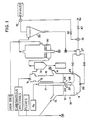
- Fig.1 illustrates a block diagram of an apparatus for smelting reduction of iron ore of the present invention.
- two Ms mean that one of the two Ms is connected to the other and two Ns mean that one of the two Ns is connected to the other.
- smelting reduction furnace 10 molten metal bath 11 and slag layer 12 are formed.
- the smelting reduction furnace has top blow oxygen lance 21 inserted down perpendicularly into it. At the end of the top blow oxygen lance, decarburizing nozzles 22 and post-combustion nozzles 23 are placed to blow oxygen gas into furnace 10.
- side tuyere 25 and bottom tuyere26 through which a gas is blown as stirring gas.
- the gas is at least one selected from the group consisting of Ar, N2, CO, CO2 and a process gas.
- the process gas is a gas generated from an apparatus for smelting and reducing iron ore according to the present invention.
- first chute 13 and second chute 14 are respectively mounted.
- first chute 13 carbonaceous material and flux which are supplied from an ordinary material feeder (not shownfor simplification), and through second chute 14, iron ore which is already prereduced in fluid bed type preheat and prereduction furnace 30, are respectively charged, by gravity, into the smelting reduction furnace.
- Gas exhaust pipe 15 for an exhaust gas discharged from furnace 10 is attached thereto.
- the fluid bed type preheat and prereduction furnace can be alternated by a shaft type furnace having a high heat efficiency or by a rotary kiln type furnace enabling an equipment cost reduction and an easy operation without any obstacle to the performance of the present invention.
- one or more gas upgrading tuyeres 9 are placed, through which powdery carbonaceous material , fuel oil or steam is blown, as a gas upgrading agent which upgrades the exhaustgas into a gas having a low OD value. Furthermore, there are provided hot cyclone 31 into which an exhaust gas is introduced from smelting reduction furnace 10 and which removes dust from the exhaust gas without losing the high heat of the exhaust gas, preheat and prereduction furnace 30, into which the exhaust gas is introduced and which preheats iron ore by means of the introduced exhaust gas, and separator 35 which receives the exhaust gas from the preheat and prereduction furnace and removes fine paticles of the iron ore included in the exhaust gas.
- pressure means 27 which mixes the fine particles of the iron ore separated from the iron ore in separator 35 with a carrier gas to form a mixture and applies a pressure to the mixture.
- the mixture is blown into furnace 10 through side tuyeres 25 and bottom tuyeres 26 switch-over valve 41 and shut-off valve 42 are provided to use the exhaust gas generated from separator 35 as a process gas.
- switch-over valve 41 and shut-off valve 42 are provided to use the exhaust gas generated from separator 35 as a process gas.
- a prat of the fine particles of the iron ore can also be returned to preheat and prereduction furnace 30 as iron ore to be preheated and prereduced , although not shown in Fig.1.
- a preheater in stead of separator 35, and to preheat the iron ore .
- a gas selected from the group consisting of Ar, N2, CO, CO2 and a process gas can be used as the carrier gas.
- Iron ore as raw material, is charged into preheat and prereduction furnace 30 from said material feeder (not shown) and, after being preheated and prereduced in furnace 30, the iron ore is charged, by grabity, into smelting reduction furnace 10 through second chute 14. Carbonaceous material and fluxes are also charged, by gravity, into furnace 10 through first chute 13. In the smelting reduction furnace, molten metal bath 11 and slag layer 12 are formed.
- An infurnace gas generated from smelting reduction furnace 10 in the slag layer 12 increases its OD by an infurnace reaction which is hereinafter explained in detail.
- the infurnace gas ascends up through gas exhaust pipe 15, being bound for prereduction furnace 30, and this infurnace gas to be an exhaust gas meets with a gas upgrading agent, which is bound to be blown into gas exhaust pipe 15 through gas upgrading tuyere 9 arranged at an upper portions of gas exhaust pipe 15. This upgrading of the exhaust gas is also hereinafter explained in detail.
- the infurnace gas thus upgraded quality is introduced, as an exhaust gas, into preheat and prereduction furnace 30.
- the iron ore is preheated and prereduced in the preheat and prereduction furnace, and then, is charged into the smelting reduction furnace through second chute 14.
- the exhaust gas goes into separator 35 and, after fine particles of iron ore are separated from the exhaust gas in the separator, the exhaust gas proceeds, by means of operating switch-over valve 41 and shut-off valve 42, on either of two courses.
- the exhaust gas is exhausted through an ordinary gas exhauster
- the other is that the exhaust gas is used as a process gas, which is blown through side tuyeres 25 and bottom tuyeres 26 into furnace 10, to be a stirring gas or a carrier gas.
- this exhaust gas can be introduced into gas exhaust pipe 15 to be mixed with the infurnace gas exhausted from the smelting reduction furnace and can be used to control a temperature of a gas which is introduced into preheat and prereduction furnace 30.
- FIG.2 schematically illustrates a behavior of gas blown through side tuyeres 25 and bottom tuyeres 26 shown in Fig,1.
- arrows 28 and 29 illustrated below oxygen lance 21, each, show directions of oxygengas injected respectively through decarburizing nozzles 22 and post-combustion nozzles 23.
- DC O2 denotes oxygen gas blown through the decarburizing nozzles and PC O2 oxygen gas blown through the post-combustion nozzles.
- gas blow operation through oxygen lance 21, side tuyere 25 and bottom tuyere 26 is carried out from the beginning to the end of the operation.
- the gas blow through the side tuyeres and the bottom tuyeres is coworked to diffuse molten metal into slag, and resultantly, the gas blow increases drastically a reduction speed.
- the present invention intends to diffuse molten metal actively into the zone where iron ore is floating in a lower portion of the slag layer by means of strong stirring to raise the reduction speed.
- a swollen portion of molten metal (shown by A in Fig.2) is formed on the surface of the molten metal by blowing a stirring gas through bottom tuyere 26 and simultaneously, a stirring gas is blown in through side tuyere 25 so as to have at least a part of the side blown stirring gas hit portion A.
- the side blowgas hits portion A of the molten metal so as for the bottom blow gas and the side blow gas to cross at right angles each other as much as possible.
- side tuyeres 25 and bottom tuyeres 26 are placed so as to satisfy a positional relation as shown in (a) or (b) of Fig.3.
- Fig.3 (a) illustrates a positional relation in case that one side tuyere 25 and one bottom tuyere 26 are used
- Fig.3 (b) illustrates a positional relation in case that three side tuyeres 25 and three bottom tuyeres26 are used.
- arrows show directions of gas blown through side tuyeres 25.
- the number is determined, depending on a capacity ofsmelting reduction furnace in use and an amount of production thereof.
- Gas blown-in through side tuyeres 25 and bottom tuyeres 26 is at least one selected from the group consisting of N2, Ar, CO, CO2 and a process gas.
- O2 gas is never used. The reason is as follows: Firstly, if O2 gas is used as the side blow gas, this involves a fundamental problem that reduction work of C containedin molten metal which has been splashed into a lower portion of slag layer 12 is impaired. Secondly, if O2 gas is used as the bottom blow gas, CO gas is produced so much that the molten metal is too strongly stirred.
- the splash of the molten metal goes into a zone of an upper portion of the slag layer and reaches to a post-combustion zone(shown by B in Fig.2) where combustion by PC O2 takes place. Consequently, the post-combustion is impaired because C contained in the molten metal reacts with O2 to be used for the the post-combustion.
- the use of O2 gas for the bottom blow raises the temperature of refractory forming bottom tuyeres 26 so high that cooling gas such as C3H3 is required to be added. This addition also increases the amount of the bottom blow gas and accelerates occurrence of the splash of the molten metal excessively.
- Fig.4 is a graphic representation showing a comparison of examples of the present invention to controls of the prior art, the examples using N2 gas as the bottom blow gas and the controls using O2 gas in stead of N2 gas as the bottom blow gas.
- the OD measured which is represented by the ordinate corresponds to an OD which is obtained from the formula (1) hereinbefore using analy of H2O, CO2, H2 and CO contained in the exhaust gas.
- OD [PC O2/(DC O2+ PC O2 + O2 in Iron ore + O2 in Carbonaceous Material + Water Adhered to Material + 1/2 ⁇ O2 in Carbonaceous Material)] (2) This is based on the assumption that the numerator "PC O2" is completely consumed in the post-combustion and thatall of O2 blown in the smelting reduction furnace is discharged, as an exhaust gas, out of the smelting reduction furnace. In case of the controls, O2 gas introduced by bottom blow is included in DC O2.
- OD determined on a theoretically calculated basis is gained, by means of formula (2), from measured amount of DC O2 and PC O2and amount of O2 and H2 included in raw material which is obtained by analysis.
- a measured OD is nearly equal to a calculated OD, it can be said that the post-combustion ratio is good.
- the post-combustion of the examples is good,but that of the controls is poor.
- the post-combustion zone is formed mainly within slag i.e. zone B and the high degree of post-combustion is performed.
- the post-combustion zone is formed and the slag is strongly stirred by the side blow gas, it can be attained that the high degree of post-combustion is procured and still the high heat transfer is obtained. Consequently,the post-combustion oxygen gas needs to be blown mainlyinto slag existing in the post-combustion area of zone B.
- a level of a top-blow lance is set so as to have an appropriate level height relative to a molten metal level and a slag level.
- the post-combustion zone fails to be formed in the slag layer and the heat transfer efficiency is lowered, while ifthe nozzles are excessively low, the post-combustionzone fails to be appropriately formed.
- the lowest level of the nozzles of the oxygen lance is equal to the lower side of the slag layer.
- Fig.5 shows a relation of a height between the top end of oxygen lance and the upper surface level of slag to the heat transfer efficiency according to the present invention, teaching that if the top end of the oxygen lance is too high from the slag surface , the good heat transfer efficiency cannot be obtained.
- Fig.6 shows a relation of a side blow gas amount to the heat transfer efficiency. It is recognized from Fig.6 that a good heat transfer efficiency can be obtained by blowing a large amount of the side blow gas through side tuyeres25 and stirring strongly the slag layer.
- the results shown in Figs.5 and 6 were obtained from an operation wherein a smelting reduction furnace with 50 tons in capacity was employed and molten metal was produced at a rate of28 t/hour.
- the present invention thanks to the high heat efficiency, a high reduction rate can be gained by means of increasing the OD as mentioned above.
- the addition amount of carbonaceous material can be reduced. Resultantly, a unit consumption of carbonaceous material can be saved and, at the same time, P content in molten metal can be reduced since most of P in the molten metal is brought with the carbonaceous material .
- the OD is set preferably to be 0.5 or more. If the OD is 0.7 or more, the reduction reaction in the smelting reduction furnace is promoted and the prereduction furnace becomes remarkably needless.
- gas with an increased OD i.e., gas of low calories is upgraded, by means of blowing powdery carbonaceous material , which is an upgrading agent, together with a carrier gas through gas gas upgrading tuyeres 9 placed at an upper portion of gas exhaust pipe 15, into an upgraded gas having a less than 0.5 OD.
- This upgraded gas is introduced into preheat and prereduction furnace 30 and iron ore can be efficiently prereduced.
- the carrier gas is at least one selected from the group consisting of N2, Ar, CO, CO2 and a process gas.
- Powdery carbonaceous material as mentioned above, which is a gas upgrading agent is usually blown in together with a carrier gas.
- gas upgrading tuyeres 9 can be charged, by gravity, into gas upgrading tuyeres 9.This can also apply to charging through an upper portion of the smelting reduction furnace.It is recommendable that as said gas upgrading agent, fuel oil or steam can be used, by taking into considerationconditions such as cost, a structure of the gas upgrading tuyeres and the exhaust gas.
- gas upgrading tuyeres 9 are placed at an upper portion of the smelting reduction furnace.
- This arrangement enables a lot of positions of the blow inlets to freely be selected vertically along the wall of gas exhaust pipe 15, and therefore, amount of blow-in gas can be easily controlled.
- those tuyeres are placed at an upside wall and upper portion side walls of the smelting reduction furnace, those portions of the smelting reduction furnace, gas exhaust pipe and other attachments thereto can be protected from being overheated since the blow-in of the gas upgrading agent lowers the temperature of the exhaust gas.
- the gas upgrading agent When the preheatand prereduction furnace is of fluid bed type, by means of blowing the gas upgrading agent into a wind box, the gas upgrading agent and the exhaust gas from the smelting reduction furnace are well mixed in the wind box, and the grade up of the exhaust gas is efficiently carried out.
Landscapes
- Engineering & Computer Science (AREA)
- Chemical & Material Sciences (AREA)
- Manufacturing & Machinery (AREA)
- Materials Engineering (AREA)
- Metallurgy (AREA)
- Organic Chemistry (AREA)
- Manufacture Of Iron (AREA)
- Manufacture And Refinement Of Metals (AREA)
- Vertical, Hearth, Or Arc Furnaces (AREA)
Abstract
Description
- The present invention relates to a method for smelting reduction of iron ore, and particularly to a method wherein carbonaceous material is used as both of fuel and a reducing agent and the iron ore which is being smelted and reduced in a basic oxygen furnace and an apparatus therefor.
- Smelting reduction method has recently been developed as a substitution for a blast furnace iron-making method, to overcome some disadvantages in that the blast furnace iron-making method requires not only an expensive construction cost but also a vast construction site.
- In a prior art smelting reduction method, iron ore is prereduced by means of an exhaust gas, and then the pre-reduced iron ore is charged together with carbonaceous material and flux into a smelting reduction furnace. Furthermore, oxygen gas and stirring gas are blown into the smelting reduction furnace. Thus, the carbonaceous materials is smelted thanks to the precharged molten metal and, at the same time, C contained in the carbonaceous material is oxidated by the oxygen gas. Through the heat produced by this oxidation, the ore is smelted and reduced by mean of C contained in the carbonaceous materials. CO gas generating in the molten metal is post-combusted, by the oxygen gas excessively blown, into CO₂ gas.The sensible heat of this CO₂ gas is transferred to slag and iron particles in the slag covering the surface of the molten metal, and then, to the molten metal.
- In this way, the iron ore is reduced to the molten metal. In this process, in order to lighten the load of reduction process in a smelting reduction furnace, iron ore is prereduced, for example, at a reduction degree of 60 to 75 % before the iron ore is charged into the smelting reduction furnace as disclosed in a Japanese Examined Patent Publication No. 434 06 /86. Resultantly, an exhaust gas from the smelting reduction furnace becomes a low oxidated gas which is highly reductive and a large amount of the exhaust gas is forced to be required.
- If iron ore before being charged into the smeltingreduction furnace is prereduced at a ratio of at least 30 % for the purpose of the lightening the load of reduction process of smelting reduction furnace, an oxidation degree(hereinafter referreto as "OD") of the exhaust gas from the smelting reduction furnace, where the OD is represented by the formula of "( H₂O+ CO₂) / ( H₂ + H₂O + CO + CO₂)" is required to be lowered. Resultantly the amount of the exhaust gas is necessarily increased, as shown, for example, in the Japanese Examined Patent Publication No. 43406/86. Thisincrease of the exhaust gas, naturally, increases the production cost. Consequently, to obtain the high prereduction ratio of the iron ore, the exhaust gas having a low OD as explained above is required, and still the retention time of the iron orestaying in the prereduction furnace has to become longer than that in the smeltingreduction furnace. Therefore, it becomes difficult to control the balancing of cycles of charge of the prereduced iron ore and discharge of the produced molten metal. This necessarily results in restricting control range strictly in the smelting reduction furnace.
- Furthermore, in order to raise a melting speed of iron ore and to obtain the speed-up of reduction of the iron ore, a method of post-combusting CO gas in the smelting reduction furnace and making use of the heat generated therefrom has conventionally been employed, wherein O₂ gas for post-combustion is introduced through tuyeres placed at upper wall of the smelting reduction furnace. However, in the conventional method, although the temperature of the exhaust gas can be elevated when the ratio of the post-combustion is raised, the sensible heat transfer to the molten metal is not sufficient. This results in being forced to discharge high temperature exhaust gas. This method has a difficulty in that such a high temperature gas will attack the inner refractory wall of the smelting reduction furnace. Therefore, it has been hitherto a generally conceived that the OD of the exhaust gas cannot be raised so much.
- In the light of the mentioned difficulty, it is an object of the present invention to provide a method for smelting reduction of iron ore wherein an efficiency of heat transfer is attained, the inner refractory wall is well protected from the heat attack due to the post combusted CO₂, an efficient preheat and prereduction is obtained and a reasonable operational performance is guaranteed.
- In accordance with the present invention, a method is provided for smelting reduction of iron ore, comprising the steps of :
preheating and prereducing iron ore ;
charging the preheated and prereduced iron ore, carbonaceous material and flux into a smelting reduction furnace;
blowing oxygen gas through a top blow oxygen lance having decarburizing nozzles and post-combustion nozzles into the smelting reduction furnace, an end of said top blow oxygen lance being arranged between an upper level of and a lower level of a slag layer ;
blowing a stirring gas through at least one side tuyere placed at the side wall of the smelting reduction furnace and at least one bottom tuyere placed at the bottom wall of the reduction furnace so that at least a part of the stirring gas introduced through the at least one side tuyere hits a swollen portion of the molten metal which is made by the stirring gas introduced through the at least one bottom tuyere ;
said stirring gas being at least one selected from the group consisting of Ar, N₂, CO, CO₂ and a process gas ;
controlling a flow rate of the oxygen gas and the stirring gas blown in the smelting reduction furnace so that OD of an infurnace gas generated from the smelting reduction furnace ranges 0.5 to 1.0.. - Furthermore, in accordance with the present invention, an apparatus for the mentioned method is provided, comprising :
a preheat and prereduction furnace which preheats and prereduces iron ore ;
a smelting reduction furnace into which the preheated and prereduced iron ore, carbonaceous material and flux are charged and in which the iron ore is smelted and reduced ;
a top blow oxygen lance having decarburizing nozzles and post-combustion nozzles and blowing oxygen gas into said smelting reduction furnace ;
at least one side tuyere placed at a side wall of the smelting reduction furnace and at least one bottom tuyere placed at a bottom of the smelting reduction furnace through which a stirring gas is respetively blown so that at least a part of the stirring gas introduced through the at least one side tuyere hits a swollen portion of the molten metal which is made by the stirring gas introduced through the at least one bottom tuyere. - The object and other objects and advantages of thepresent invention will become apparent from the detailed description tofollow, taken in conjunction with the appended drawings.
- Fig.1 is a block diagram illustrating an embodiment of an apparatus for smelting reduction of iron ore of the present invention
- Fig.2 is a view illustrating a gas flow in a smelting reduction furnace forming a part of the apparatus shown in Fig 1 ;
- Fig.3 is a view illustrating a position relation between side tuyeres and bottom tuyeres of the present invention ;
- Fig.4 is a graphic representation showing comparison of OD calculated according to the present invention with OD actually measured ;
- Fig.5 is a graphic representation showing a relation of a heat transfer efficiency to a level height of an oxygen lance of the present invention ; and
- Fig.6 is a graphic representation showing a relation of a heat transfer efficiency to a side blow gas of the present invention.
- The inventors obtained some findings, based on the study of the mechanism of the smelting reduction furnace and the measures specifically responding to improvement in the heat transfer efficiency and to promotion of the reduction of iron ore.
- ① According to the basic concept in the prior arts as mentioned above, the post-combustion ratio cannot be greatly improved due to the technological limit in improving the heat transfer efficiency and damage of theinner walls of the smelting reduction furnace due to the post-combustion super heat. However, if oxygen gas is blown into a slag layer and, at the same time, the slag is strongly stirred so that the post-combustion is performed mainly within the slag layer, the high degree of post-combustion can be procured, the high heat transfer efficiency being maintained. Thus, thanks to the high degree of post-combustion, slag and molten metal shots contained in slag are well heat-supplied so that the reduction of iron ore by C represented in the formula given below proceeds efficiently where C means carbon contained in the molten metal, either in shape of metal droplets or metal bath.
Fe₂O₃ + 3C → 2Fe +3CO - ② In the prior art method, there are some examples wherein oxygen bottom blow is carried out during the whole or a certain period of the reduction operation. Such oxygen bottom blow is disadvantageous to the high degree of post-combustion. Namely, when the oxygen bottom blow is carried out, a large amount of CO gas is produced in molten metal and the molten metal is strongly stirred. Resultantly, splash of the molten metal goes into a post-combustion zone and C contained in the splashed molten metal reacts with the oxygen gas, thereby the post-combustion ratio being lowered. Consequently, it is necessary to avoid the oxygen bottom blow, regardless of the period of the blowing.
- Based on these knowledge and experience, the present invention enables an efficient reduction operation, setting the following conditions:
- (a) Side blowing and bottom blowing of stirring gas are combined so that molten metal is actively diffused into the zone where iron ore exists in a slag layer and the reduction work of iron ore by C contained in the molten metal is promoted.
- (b) Decarburization nozzles and post-combustion nozzles are placed in a top blow oxygen lance and oxygen gas is blown therethrough so that a predetermined OD level or more is procured . The oxygen gas through the post-combustion nozzeles is introduced into the slag layerto form, in the slag layer, a zone where the post-combustion is carried out. The slag layer is strongly stirred by a side blow gas as well as by a top blow gas.Thus, the heat generated by the post-combustion is transferred to iron ore.
- (c) As stirring gas blown, through the side wall as well as bottom wall, at least one selected from the group consisting of Ar, N₂,CO, CO₂ and a process gas is used so as for the post-combustion degree not to go down.Oxygen gas is not used for this purpose.
- In addition to the foregoing, in the present invention, powdery carbonaceous material, fuel oil or steam is blown through an upside wall portion or an upper portion of side walls of the smelting reduction furnace, a gas exhaust pipe for anexhaust gas provided with the reduction furnace or gas upgrading tuyeres at a preheat and prereduction furnace. This blowing upgrades gases generated in the smelting reduction furnace to lower an OD of the generated infurnace gases, and those upgraded gases contribute to a high prereduction degree. The temperature of the exhaust gas is controlled to preferably ranges 300 to 1,300 °C. If the temperature is less than 300°C, the preheat effect is not expected and in addition, it fears that the tar trouble occurs during the process of upgrading the gases. Contrarily, if it is over 1,300 °C, there is a problem of heat resistance in the equipment. Furthermore, it is also advantageous in the heat resistance of the equipment to lower the temperature by means of upgrading the gases.
- Now referring specifically to the appended drawings, an embodiment of an apparatus for smelting reduction of iron ore of the present invention will be described. Fig.1 illustrates a block diagram of an apparatus for smelting reduction of iron ore of the present invention. In Fig.1, two Ⓜs mean that one of the two Ⓜs is connected to the other and two Ⓝs mean that one of the two Ⓝs is connected to the other. In
smelting reduction furnace 10,molten metal bath 11 andslag layer 12 are formed. The smelting reduction furnace has topblow oxygen lance 21 inserted down perpendicularly into it. At the end of the top blow oxygen lance, decarburizingnozzles 22 andpost-combustion nozzles 23 are placed to blow oxygen gas intofurnace 10. In side walls and a bottom wall offurnace 10, there are respectively placedside tuyere 25 and bottom tuyere26 through which a gas is blown as stirring gas. The gas is at least one selected from the group consisting of Ar, N₂, CO, CO₂ and a process gas. The process gas is a gas generated from an apparatus for smelting and reducing iron ore according to the present invention. - At upper portions of
furnace 10,first chute 13 andsecond chute 14 are respectively mounted. Throughfirst chute 13, carbonaceous material and flux which are supplied from an ordinary material feeder (not shownfor simplification), and throughsecond chute 14, iron ore which is already prereduced in fluid bed type preheat andprereduction furnace 30, are respectively charged, by gravity, into the smelting reduction furnace.Gas exhaust pipe 15 for an exhaust gas discharged fromfurnace 10 is attached thereto. It should be noted that the fluid bed type preheat and prereduction furnace can be alternated by a shaft type furnace having a high heat efficiency or by a rotary kiln type furnace enabling an equipment cost reduction and an easy operation without any obstacle to the performance of the present invention. - At upper portions of said gas exhaust pipe, one or more
gas upgrading tuyeres 9 are placed, through which powdery carbonaceous material , fuel oil or steam is blown, as a gas upgrading agent which upgrades the exhaustgas into a gas having a low OD value. Furthermore, there are providedhot cyclone 31 into which an exhaust gas is introduced fromsmelting reduction furnace 10 and which removes dust from the exhaust gas without losing the high heat of the exhaust gas, preheat andprereduction furnace 30, into which the exhaust gas is introduced and which preheats iron ore by means of the introduced exhaust gas, andseparator 35 which receives the exhaust gas from the preheat and prereduction furnace and removes fine paticles of the iron ore included in the exhaust gas. There is also pressure means 27 which mixes the fine particles of the iron ore separated from the iron ore inseparator 35 with a carrier gas to form a mixture and applies a pressure to the mixture. The mixture is blown intofurnace 10 throughside tuyeres 25 andbottom tuyeres 26 switch-overvalve 41 and shut-offvalve 42 are provided to use the exhaust gas generated fromseparator 35 as a process gas. It should be noted that a prat of the fine particles of the iron ore can also be returned to preheat andprereduction furnace 30 as iron ore to be preheated and prereduced , although not shown in Fig.1. Furthermore, in view of making use of heat, it is effective to arrange a preheater in stead ofseparator 35, and to preheat the iron ore . As the carrier gas, a gas selected from the group consisting of Ar, N₂, CO, CO₂ and a process gas can be used. - Secondly, a method for smelting reduction of iron ore which is used in an apparatus for smelting reduction as explained in the foregoing will be described. Iron ore , as raw material, is charged into preheat and
prereduction furnace 30 from said material feeder (not shown) and, after being preheated and prereduced infurnace 30, the iron ore is charged, by grabity, intosmelting reduction furnace 10 throughsecond chute 14. Carbonaceous material and fluxes are also charged, by gravity, intofurnace 10 throughfirst chute 13. In the smelting reduction furnace,molten metal bath 11 andslag layer 12 are formed. An infurnace gas generated fromsmelting reduction furnace 10 in theslag layer 12 increases its OD by an infurnace reaction which is hereinafter explained in detail. The infurnace gas ascends up throughgas exhaust pipe 15, being bound forprereduction furnace 30, and this infurnace gas to be an exhaust gas meets with a gas upgrading agent, which is bound to be blown intogas exhaust pipe 15 throughgas upgrading tuyere 9 arranged at an upper portions ofgas exhaust pipe 15. This upgrading of the exhaust gas is also hereinafter explained in detail. - The infurnace gas which has been increased, due to the infurnace reaction, in OD represented by the formula given below is decreased, by means of gas upgrading agent, in the OD:
OD = (H₂O + CO₂)/(H₂ + H₂O + CO + CO₂) (1) - The infurnace gas thus upgraded quality is introduced, as an exhaust gas, into preheat and
prereduction furnace 30. The iron ore is preheated and prereduced in the preheat and prereduction furnace, and then, is charged into the smelting reduction furnace throughsecond chute 14. In the meantime, the exhaust gas goes intoseparator 35 and, after fine particles of iron ore are separated from the exhaust gas in the separator, the exhaust gas proceeds, by means of operating switch-overvalve 41 and shut-offvalve 42, on either of two courses. One of the two course is that the exhaust gas is exhausted through an ordinary gas exhauster , and the other is that the exhaust gas is used as a process gas, which is blown throughside tuyeres 25 andbottom tuyeres 26 intofurnace 10, to be a stirring gas or a carrier gas. Furthermore this exhaust gas can be introduced intogas exhaust pipe 15 to be mixed with the infurnace gas exhausted from the smelting reduction furnace and can be used to control a temperature of a gas which is introduced into preheat andprereduction furnace 30. - Now, with specific reference to the drawings of Figs. 2 to 6, relation between gas blow into
smelting reduction furnace 10 and infurnace reaction will be examined in detail. Fig.2 schematically illustrates a behavior of gas blown throughside tuyeres 25 andbottom tuyeres 26 shown in Fig,1. In Fig. 2,arrows oxygen lance 21, each, show directions of oxygengas injected respectively throughdecarburizing nozzles 22 and post-combustion nozzles 23.DC O₂ denotes oxygen gas blown through the decarburizing nozzles and PC O₂ oxygen gas blown through the post-combustion nozzles. Throughout the reduction operation, gas blow operation throughoxygen lance 21,side tuyere 25 andbottom tuyere 26 is carried out from the beginning to the end of the operation. The gas blow through the side tuyeres and the bottom tuyeres is coworked to diffuse molten metal into slag, and resultantly, the gas blow increases drastically a reduction speed. - As mentioned in the beginning of the detailed description, based on the finding that reduction of iron ore existing in
slag layer 12 proceeds mostly by making use of C contained in molten metal as a reducing agent, the present invention intends to diffuse molten metal actively into the zone where iron ore is floating in a lower portion of the slag layer by means of strong stirring to raise the reduction speed. For this purpose, a swollen portion of molten metal (shown by A in Fig.2) is formed on the surface of the molten metal by blowing a stirring gas throughbottom tuyere 26 and simultaneously, a stirring gas is blown in throughside tuyere 25 so as to have at least a part of the side blown stirring gas hit portion A. By this side blow gas, molten metal at the swollen portion of A is splashed into the slag. An apparent specific gravity of the slag ranges normally 0.1 to 0.5, while a bulk specific gravity of the iron ore ranges approximately 2 to 5. Consequently,iron ore 16 contained in the slag is floating concentratedly in a lower portion ofslag layer 12. When the swollen portion of A of the molten metal is splashed by means of the side blown stirring gas, splashedmolten metal 17 is diffused into a zone of a lower portion ofslag layer 12. C contained in the splashed molten metal reduces the iron ore . Thus, a high reduction speed is performed. To obtain such an effect, it is preferable that the side blowgas hits portion A of the molten metal so as for the bottom blow gas and the side blow gas to cross at right angles each other as much as possible. In the horizontal direction ,side tuyeres 25 andbottom tuyeres 26 are placed so as to satisfy a positional relation as shown in (a) or (b) of Fig.3. - Fig.3 (a) illustrates a positional relation in case that one
side tuyere 25 and onebottom tuyere 26 are used, and Fig.3 (b) illustrates a positional relation in case that threeside tuyeres 25 and three bottom tuyeres26 are used. In this Fig.3, arrows show directions of gas blown throughside tuyeres 25. Of course, the number and the position ofside tuyeres 25 andbottom tuyeres 26 are not always subject soley to those shown in Fig.3. The number is determined, depending on a capacity ofsmelting reduction furnace in use and an amount of production thereof. Furthermore a large amount of gas is required to beblown through both ofside tuyeres 25 andbottom tuyeres 26. The amount of the gas blows is determined, depending on an amount of molten metal and a depth of the molten metal. In addition to the diffusion work, the side blow gas stirs an upper portion of slag layerwhere a zone of the post combustion is formed. This is also hereinafter detailed. - Gas blown-in through
side tuyeres 25 andbottom tuyeres 26 is at least one selected from the group consisting of N₂, Ar, CO, CO₂ and a process gas. O₂ gas, however, is never used. The reason is as follows: Firstly, if O₂ gas is used as the side blow gas, this involves a fundamental problem that reduction work of C containedin molten metal which has been splashed into a lower portion ofslag layer 12 is impaired. Secondly, if O₂ gas is used as the bottom blow gas, CO gas is produced so much that the molten metal is too strongly stirred. As a result, the splash of the molten metal goes into a zone of an upper portion of the slag layer and reaches to a post-combustion zone(shown by B in Fig.2) where combustion by PC O₂ takes place. Consequently, the post-combustion is impaired because C contained in the molten metal reacts with O₂ to be used for the the post-combustion.Furthermore, the use of O₂ gas for the bottom blow raises the temperature of refractory formingbottom tuyeres 26 so high that cooling gas such as C₃H₃ is required to be added. This addition also increases the amount of the bottom blow gas and accelerates occurrence of the splash of the molten metal excessively. - Fig.4 is a graphic representation showing a comparison of examples of the present invention to controls of the prior art, the examples using N₂ gas as the bottom blow gas and the controls using O₂ gas in stead of N₂ gas as the bottom blow gas. Namely, in this graph, the OD measured which is represented by the ordinate corresponds to an OD which is obtained from the formula (1) hereinbefore using analy of H₂O, CO₂, H₂ and CO contained in the exhaust gas. On the other hand, the OD which is represented by the abscissa is given by formula(2) :
OD=[PC O₂/(DC O₂+ PC O₂ + O₂ in Iron ore
+ O₂ in Carbonaceous Material
+ Water Adhered to Material
+ 1/2 · O₂ in Carbonaceous Material)] (2)
This is based on the assumption that the numerator "PC O₂" is completely consumed in the post-combustion and thatall of O₂ blown in the smelting reduction furnace is discharged, as an exhaust gas, out of the smelting reduction furnace. In case of the controls, O₂ gas introduced by bottom blow is included in DC O₂. OD determined on a theoretically calculated basis is gained, by means of formula (2), from measured amount of DC O₂ and PC O₂and amount of O₂ and H₂ included in raw material which is obtained by analysis. When, as seen from the examples, a measured OD is nearly equal to a calculated OD, it can be said that the post-combustion ratio is good. As clealy seen from Fig.4, the post-combustion of the examples is good,but that of the controls is poor. - In the present invention, the post-combustion zone is formed mainly within slag i.e. zone B and the high degree of post-combustion is performed. In this way, by a method wherein the the post-combustion zone is formed and the slag is strongly stirred by the side blow gas, it can be attained that the high degree of post-combustion is procured and still the high heat transfer is obtained. Consequently,the post-combustion oxygen gas needs to be blown mainlyinto slag existing in the post-combustion area of zone B.
- It is specifically reqired that a level of a top-blow lance is set so as to have an appropriate level height relative to a molten metal level and a slag level. In other words, if nozzles of
oxygen lance 21 are excessively higher than the upper surface ofslag layer 12, the post-combustion zone fails to be formed in the slag layer and the heat transfer efficiency is lowered, while ifthe nozzles are excessively low, the post-combustionzone fails to be appropriately formed. The lowest level of the nozzles of the oxygen lance is equal to the lower side of the slag layer. - Fig.5 shows a relation of a height between the top end of oxygen lance and the upper surface level of slag to the heat transfer efficiency according to the present invention, teaching that if the top end of the oxygen lance is too high from the slag surface , the good heat transfer efficiency cannot be obtained. Fig.6 shows a relation of a side blow gas amount to the heat transfer efficiency. It is recognized from Fig.6 that a good heat transfer efficiency can be obtained by blowing a large amount of the side blow gas through side tuyeres25 and stirring strongly the slag layer. The results shown in Figs.5 and 6 were obtained from an operation wherein a smelting reduction furnace with 50 tons in capacity was employed and molten metal was produced at a rate of28 t/hour.
- According to the present invention, thanks to the high heat efficiency, a high reduction rate can be gained by means of increasing the OD as mentioned above. In addition to this, thanks to the raise of the OD, the addition amount of carbonaceous material can be reduced. Resultantly, a unit consumption of carbonaceous material can be saved and, at the same time, P content in molten metal can be reduced since most of P in the molten metal is brought with the carbonaceous material . Furthermore, when the OD becomes high, desulferization by evaporation is activated, and therefore, S content in the molten metal can be reduced. From these view points, the OD is set preferably to be 0.5 or more. If the OD is 0.7 or more, the reduction reaction in the smelting reduction furnace is promoted and the prereduction furnace becomes remarkably needless.
- In the manner as mentiond above, gas with an increased OD i.e., gas of low calories is upgraded, by means of blowing powdery carbonaceous material , which is an upgrading agent, together with a carrier gas through gas
gas upgrading tuyeres 9 placed at an upper portion ofgas exhaust pipe 15, into an upgraded gas having a less than 0.5 OD. This upgraded gas is introduced into preheat andprereduction furnace 30 and iron ore can be efficiently prereduced. The carrier gas is at least one selected from the group consisting of N₂, Ar, CO, CO₂ and a process gas. Powdery carbonaceous material as mentioned above, which is a gas upgrading agent, is usually blown in together with a carrier gas. Depending on a particle size of carbonaceous material , however, they can be charged, by gravity, into gas upgrading tuyeres 9.This can also apply to charging through an upper portion of the smelting reduction furnace.It is recommendable that as said gas upgrading agent, fuel oil or steam can be used, by taking into considerationconditions such as cost, a structure of the gas upgrading tuyeres and the exhaust gas. - In this embodiment, as mentioned above,
gas upgrading tuyeres 9 are placed at an upper portion of the smelting reduction furnace. This arrangement enables a lot of positions of the blow inlets to freely be selected vertically along the wall ofgas exhaust pipe 15, and therefore, amount of blow-in gas can be easily controlled. Furthermore, when those tuyeres are placed at an upside wall and upper portion side walls of the smelting reduction furnace, those portions of the smelting reduction furnace, gas exhaust pipe and other attachments thereto can be protected from being overheated since the blow-in of the gas upgrading agent lowers the temperature of the exhaust gas. When the preheatand prereduction furnace is of fluid bed type, by means of blowing the gas upgrading agent into a wind box, the gas upgrading agent and the exhaust gas from the smelting reduction furnace are well mixed in the wind box, and the grade up of the exhaust gas is efficiently carried out. - Lastly, specific values obtained from the results of the operation of the examples of the present invention are listed in Table 1. These examples were obtained on the same conditions as those of Figs.5 and 6. In the Table, comparison of a case of the gas upgrading being carried out and a case of the gas upgrading not being carried out is shown. The respective OD values were calculated by formula(2) given hereinbefore,using the compositions of the exhast gases in table 1. The OD value of the upgraded gas is 0.24, while the OD of the non-upgraded gas is 0.51. It is clear that the upgraded gas has an OD value much lower than that of the non-upgraded gas. Furthermore the temperature of the upgraded gas is lower than that of the non-upgraded gas.
- While the present invention has been particularly showen and described with reference to preferred embodiments thereof, it will be understood by those skilled in the art that the foregoing and other changes in form and details can be made therein without departing from the spirit and scope of the present invention.
Table 1 Non-upgraded Gas Upgraded Gas Coal 328 kg/min(in molten metal bath) 225 kg/min(in molten metal bath) 76 kg/min ( for upgrading ) Iron Ore 724 kg/min(in molten metal bath) 720 kg/min(in molten metal bath) CaCO₃ 72 kg/min(in molten metal bath) 74 kg/min(in molten metal bath) O₂ 232 Nm³/min 165 Nm³/min Exhaust Gas CO 44 % 68 % CO₂ 34 % 14 % H₂ 5 % 8 % H₂O 17 % 17 % Temp. 1,740 °C 1,650 °C
Claims (14)
blowing a stirring gas through at least one side tuyere(25) placed at side wall of said smelting reduction furnace(10) and at least one bottom tuyere(26) placed at bottom wall of said smelting reduction furnace (10) so that at least a part of said stirring gas introduced through said at least one side tuyere (25) hits a swollen portion of the molten metal by said stirring gas introduced through said at least one bottom tuyere(25);
said stirring gas being at least one selected from the group consisting of Ar, N₂, CO, CO₂ and a process gas ; and
controlling a flow rate of said oxygen gas and said stirring gas blown in said smelting reduction furnace (10) so that an OD of infurnace gas of said smelting reduction furnace (10) ranges 0.5 to 1.0. where said OD is represented by the following formula :
OD = (H₂O + CO₂ ) / ( H₂+ H₂O + CO + CO₂ ).
at least one side tuyere (25) placed at a side wall of the smelting reduction furnace (10) and bottom tuyers (26) placed at a bottom of the smelting reduction furnace (10) through which a stirring gas is respectively blown in the smelting reduction furnace (10) so that at least a part of said stirring gas introduced through said at least one side tuyere(25) hits a swollen portion of the molten metal by said stirring gas introduced through said at least one bottom tuyere (26).
Priority Applications (1)
| Application Number | Priority Date | Filing Date | Title |
|---|---|---|---|
| AT88119803T ATE101655T1 (en) | 1987-11-30 | 1988-11-28 | METHOD AND DEVICE FOR SMELTING REDUCTION OF IRON ORES. |
Applications Claiming Priority (6)
| Application Number | Priority Date | Filing Date | Title |
|---|---|---|---|
| JP62303940A JP2638861B2 (en) | 1987-11-30 | 1987-11-30 | Melt reduction method |
| JP303940/87 | 1987-11-30 | ||
| JP63028584A JPH01205017A (en) | 1988-02-09 | 1988-02-09 | Smelting reduction method |
| JP28586/88 | 1988-02-09 | ||
| JP28584/88 | 1988-02-09 | ||
| JP2858688A JP2668913B2 (en) | 1988-02-09 | 1988-02-09 | Smelting reduction method |
Publications (3)
| Publication Number | Publication Date |
|---|---|
| EP0318896A2 true EP0318896A2 (en) | 1989-06-07 |
| EP0318896A3 EP0318896A3 (en) | 1991-03-27 |
| EP0318896B1 EP0318896B1 (en) | 1994-02-16 |
Family
ID=27286248
Family Applications (1)
| Application Number | Title | Priority Date | Filing Date |
|---|---|---|---|
| EP88119803A Expired - Lifetime EP0318896B1 (en) | 1987-11-30 | 1988-11-28 | Method for smelting reduction of iron ore and apparatus therefor |
Country Status (7)
| Country | Link |
|---|---|
| US (2) | US5000784A (en) |
| EP (1) | EP0318896B1 (en) |
| KR (1) | KR910006037B1 (en) |
| AT (1) | ATE101655T1 (en) |
| BR (1) | BR8806278A (en) |
| CA (1) | CA1337241C (en) |
| DE (1) | DE3887838T2 (en) |
Cited By (7)
| Publication number | Priority date | Publication date | Assignee | Title |
|---|---|---|---|---|
| EP0534020A1 (en) * | 1990-07-18 | 1993-03-31 | Kawasaki Jukogyo Kabushiki Kaisha | Molten metal producing and refining method |
| US5246482A (en) * | 1990-06-29 | 1993-09-21 | Kawasaki Jukogyo Kabushiki Kaisha | Molten metal producing and refining method |
| EP0320999B1 (en) * | 1987-12-18 | 1994-03-30 | Nkk Corporation | Method for smelting reduction of iron ore and apparatus therefor |
| EP0902093A1 (en) * | 1997-09-03 | 1999-03-17 | The Boc Group, Inc. | Iron manufacturing |
| WO1999025880A1 (en) * | 1997-11-13 | 1999-05-27 | Anatoly Lukich Nikolaev | Method for the direct production of steel from iron-containing materials in a converter |
| CN112325628A (en) * | 2020-10-24 | 2021-02-05 | 河北小蜜蜂工具集团有限公司 | Reduction furnace |
| WO2022069972A1 (en) * | 2020-09-29 | 2022-04-07 | Frederik Petrus Greyling | Process and system for melting agglomerates |
Families Citing this family (30)
| Publication number | Priority date | Publication date | Assignee | Title |
|---|---|---|---|---|
| WO1993006251A1 (en) * | 1991-09-20 | 1993-04-01 | Ausmelt Pty. Ltd. | Process for production of iron |
| DE4215858C2 (en) * | 1992-05-14 | 1995-09-14 | Metallgesellschaft Ag | Method and device for the production of molten steel |
| US5572544A (en) * | 1994-07-21 | 1996-11-05 | Praxair Technology, Inc. | Electric arc furnace post combustion method |
| US5733358A (en) * | 1994-12-20 | 1998-03-31 | Usx Corporation And Praxair Technology, Inc. | Process and apparatus for the manufacture of steel from iron carbide |
| AUPN226095A0 (en) | 1995-04-07 | 1995-05-04 | Technological Resources Pty Limited | A method of producing metals and metal alloys |
| US5885322A (en) * | 1996-03-22 | 1999-03-23 | Steel Technology Corporation | Method for reducing iron losses in an iron smelting process |
| AUPO426096A0 (en) | 1996-12-18 | 1997-01-23 | Technological Resources Pty Limited | Method and apparatus for producing metals and metal alloys |
| AUPO426396A0 (en) | 1996-12-18 | 1997-01-23 | Technological Resources Pty Limited | A method of producing iron |
| AUPO944697A0 (en) * | 1997-09-26 | 1997-10-16 | Technological Resources Pty Limited | A method of producing metals and metal alloys |
| US5943360A (en) * | 1998-04-17 | 1999-08-24 | Fuchs Systems, Inc. | Electric arc furnace that uses post combustion |
| AUPP442598A0 (en) | 1998-07-01 | 1998-07-23 | Technological Resources Pty Limited | Direct smelting vessel |
| MY119760A (en) | 1998-07-24 | 2005-07-29 | Tech Resources Pty Ltd | A direct smelting process |
| AUPP483898A0 (en) | 1998-07-24 | 1998-08-13 | Technological Resources Pty Limited | A direct smelting process & apparatus |
| AUPP554098A0 (en) | 1998-08-28 | 1998-09-17 | Technological Resources Pty Limited | A process and an apparatus for producing metals and metal alloys |
| AUPP570098A0 (en) | 1998-09-04 | 1998-10-01 | Technological Resources Pty Limited | A direct smelting process |
| AUPP647198A0 (en) | 1998-10-14 | 1998-11-05 | Technological Resources Pty Limited | A process and an apparatus for producing metals and metal alloys |
| AUPP805599A0 (en) | 1999-01-08 | 1999-02-04 | Technological Resources Pty Limited | A direct smelting process |
| AUPQ083599A0 (en) | 1999-06-08 | 1999-07-01 | Technological Resources Pty Limited | Direct smelting vessel |
| AUPQ152299A0 (en) | 1999-07-09 | 1999-08-05 | Technological Resources Pty Limited | Start-up procedure for direct smelting process |
| AUPQ205799A0 (en) | 1999-08-05 | 1999-08-26 | Technological Resources Pty Limited | A direct smelting process |
| AUPQ213099A0 (en) | 1999-08-10 | 1999-09-02 | Technological Resources Pty Limited | Pressure control |
| AUPQ308799A0 (en) | 1999-09-27 | 1999-10-21 | Technological Resources Pty Limited | A direct smelting process |
| AUPQ346399A0 (en) | 1999-10-15 | 1999-11-11 | Technological Resources Pty Limited | Stable idle procedure |
| AUPQ365799A0 (en) | 1999-10-26 | 1999-11-18 | Technological Resources Pty Limited | A direct smelting apparatus and process |
| US6602321B2 (en) | 2000-09-26 | 2003-08-05 | Technological Resources Pty. Ltd. | Direct smelting process |
| RU2181383C1 (en) * | 2001-07-12 | 2002-04-20 | ОАО "НОСТА" (ОХМК) - Открытое акционерное общество Орско-Халиловский металлургический комбинат | Method of reusing phenol-containing waste water |
| US7238222B2 (en) * | 2005-03-01 | 2007-07-03 | Peterson Oren V | Thermal synthesis production of steel |
| US20060228294A1 (en) * | 2005-04-12 | 2006-10-12 | Davis William H | Process and apparatus using a molten metal bath |
| CN112011661A (en) * | 2020-08-07 | 2020-12-01 | 新疆八一钢铁股份有限公司 | Efficient nitrogen-saving method for tuyere of Ou metallurgical furnace |
| CN116103501B (en) * | 2023-02-24 | 2024-09-20 | 中国恩菲工程技术有限公司 | Synergistic smelting method of steel soot and red mud |
Family Cites Families (8)
| Publication number | Priority date | Publication date | Assignee | Title |
|---|---|---|---|---|
| US3711275A (en) * | 1969-10-13 | 1973-01-16 | M Johnsson | Method for the production of liquid pig iron or steel directly of dressed ore |
| LU83826A1 (en) * | 1981-12-09 | 1983-09-01 | Arbed | METHOD AND DEVICE FOR THE DIRECT PRODUCTION OF LIQUID IRON |
| DE3318005C2 (en) * | 1983-05-18 | 1986-02-20 | Klöckner CRA Technologie GmbH, 4100 Duisburg | Process for making iron |
| DE3418085A1 (en) * | 1984-05-16 | 1985-11-28 | Klöckner CRA Technologie GmbH, 4100 Duisburg | Iron production process |
| JPS6143406A (en) * | 1984-08-08 | 1986-03-03 | Mitsubishi Electric Corp | Winding device |
| AT385051B (en) * | 1986-08-07 | 1988-02-10 | Voest Alpine Ag | MILL PLANT AND METHOD FOR PRODUCING STEEL |
| US4936908A (en) * | 1987-09-25 | 1990-06-26 | Nkk Corporation | Method for smelting and reducing iron ores |
| US4995906A (en) * | 1987-12-18 | 1991-02-26 | Nkk Corporation | Method for smelting reduction of iron ore |
-
1988
- 1988-11-25 CA CA000584123A patent/CA1337241C/en not_active Expired - Fee Related
- 1988-11-28 US US07/276,612 patent/US5000784A/en not_active Expired - Lifetime
- 1988-11-28 AT AT88119803T patent/ATE101655T1/en not_active IP Right Cessation
- 1988-11-28 DE DE3887838T patent/DE3887838T2/en not_active Expired - Fee Related
- 1988-11-28 EP EP88119803A patent/EP0318896B1/en not_active Expired - Lifetime
- 1988-11-29 BR BR888806278A patent/BR8806278A/en not_active IP Right Cessation
- 1988-11-30 KR KR1019880015891A patent/KR910006037B1/en not_active Expired
-
1990
- 1990-05-08 US US07/520,785 patent/US5065985A/en not_active Expired - Lifetime
Cited By (10)
| Publication number | Priority date | Publication date | Assignee | Title |
|---|---|---|---|---|
| EP0320999B1 (en) * | 1987-12-18 | 1994-03-30 | Nkk Corporation | Method for smelting reduction of iron ore and apparatus therefor |
| US5246482A (en) * | 1990-06-29 | 1993-09-21 | Kawasaki Jukogyo Kabushiki Kaisha | Molten metal producing and refining method |
| EP0534020A1 (en) * | 1990-07-18 | 1993-03-31 | Kawasaki Jukogyo Kabushiki Kaisha | Molten metal producing and refining method |
| EP0902093A1 (en) * | 1997-09-03 | 1999-03-17 | The Boc Group, Inc. | Iron manufacturing |
| US6214084B1 (en) | 1997-09-03 | 2001-04-10 | The Boc Group, Inc. | Iron manufacturing process |
| WO1999025880A1 (en) * | 1997-11-13 | 1999-05-27 | Anatoly Lukich Nikolaev | Method for the direct production of steel from iron-containing materials in a converter |
| WO2022069972A1 (en) * | 2020-09-29 | 2022-04-07 | Frederik Petrus Greyling | Process and system for melting agglomerates |
| NL2026572B1 (en) * | 2020-09-29 | 2022-05-30 | Petrus Greyling Frederik | Process and system for melting agglomerates |
| CN112325628A (en) * | 2020-10-24 | 2021-02-05 | 河北小蜜蜂工具集团有限公司 | Reduction furnace |
| CN112325628B (en) * | 2020-10-24 | 2022-11-11 | 河北小蜜蜂工具集团有限公司 | Reduction furnace |
Also Published As
| Publication number | Publication date |
|---|---|
| DE3887838T2 (en) | 1994-07-07 |
| BR8806278A (en) | 1989-08-15 |
| KR900008050A (en) | 1990-06-02 |
| AU608091B2 (en) | 1991-03-21 |
| ATE101655T1 (en) | 1994-03-15 |
| EP0318896B1 (en) | 1994-02-16 |
| DE3887838D1 (en) | 1994-03-24 |
| KR910006037B1 (en) | 1991-08-12 |
| EP0318896A3 (en) | 1991-03-27 |
| AU2491688A (en) | 1989-06-01 |
| CA1337241C (en) | 1995-10-10 |
| US5065985A (en) | 1991-11-19 |
| US5000784A (en) | 1991-03-19 |
Similar Documents
| Publication | Publication Date | Title |
|---|---|---|
| EP0318896B1 (en) | Method for smelting reduction of iron ore and apparatus therefor | |
| EP0308925B1 (en) | Method and apparatus for smelting and reducing iron ores | |
| EP1076102B1 (en) | Pressure control in direct melting process | |
| EP0592830A1 (en) | A method for intensifying the reactions in metallurgical reaction vessels | |
| JP2008255494A (en) | Direct smelting method for producing metal from metal oxide | |
| US6837916B2 (en) | Smelting reduction method | |
| EP0320999B1 (en) | Method for smelting reduction of iron ore and apparatus therefor | |
| EP1320633B1 (en) | A direct smelting process and apparatus | |
| KR100707916B1 (en) | Direct smelting method | |
| EP0419868B1 (en) | Method of in-bath smelting reduction of metals and in-bath smelting reduction furnace | |
| US4740242A (en) | Method for transferring heat to molten metal, and apparatus therefor | |
| EP0905260A1 (en) | Smelting reduction apparatus and method of operating the same | |
| JPH01162710A (en) | Melting reduction method and equipment | |
| JP4005683B2 (en) | Vertical furnace operation method for treating powdered waste | |
| JPH01104709A (en) | Melting reduction method | |
| CN1043344A (en) | Iron ore smelting reduction method and equipment | |
| JPH1121610A (en) | Operating method of gas blowing lance and converter type refining furnace | |
| JPH01104707A (en) | Smelting reduction method | |
| JPH0196313A (en) | Melting reduction method | |
| JPH01205015A (en) | Melting reduction method and equipment | |
| JPH11158521A (en) | Operating method of vertical furnace | |
| JPH08143923A (en) | Apparatus for producing pig iron using self-reducible ore block as main raw material and production of pig iron | |
| JPH01104706A (en) | Melting reduction method |
Legal Events
| Date | Code | Title | Description |
|---|---|---|---|
| PUAI | Public reference made under article 153(3) epc to a published international application that has entered the european phase |
Free format text: ORIGINAL CODE: 0009012 |
|
| 17P | Request for examination filed |
Effective date: 19881128 |
|
| AK | Designated contracting states |
Kind code of ref document: A2 Designated state(s): AT BE DE ES FR GB IT NL SE |
|
| RIN1 | Information on inventor provided before grant (corrected) |
Inventor name: YAMADA, KENZO C/O PATENT & LICENSE AND Inventor name: TANABE, HARYOSHI C/O PATENT & LICENSE AND Inventor name: INOUE, SHIGERU C/O PATENT & LICENSE AND Inventor name: IWASAKI, KATSUHIRO C/O PATENT & LICENSE AND Inventor name: TAKAHASHI, KENJI C/O PATENT & LICENSE AND Inventor name: KAWAKAMI, MASAHIRO C/O PATENT & LICENSE AND Inventor name: TERADA, OSAMU C/O PATENT & LICENSE AND |
|
| RAP1 | Party data changed (applicant data changed or rights of an application transferred) |
Owner name: NKK CORPORATION |
|
| PUAL | Search report despatched |
Free format text: ORIGINAL CODE: 0009013 |
|
| AK | Designated contracting states |
Kind code of ref document: A3 Designated state(s): AT BE DE ES FR GB IT NL SE |
|
| 17Q | First examination report despatched |
Effective date: 19920320 |
|
| GRAA | (expected) grant |
Free format text: ORIGINAL CODE: 0009210 |
|
| AK | Designated contracting states |
Kind code of ref document: B1 Designated state(s): AT BE DE ES FR GB IT NL SE |
|
| PG25 | Lapsed in a contracting state [announced via postgrant information from national office to epo] |
Ref country code: BE Effective date: 19940216 Ref country code: IT Free format text: LAPSE BECAUSE OF FAILURE TO SUBMIT A TRANSLATION OF THE DESCRIPTION OR TO PAY THE FEE WITHIN THE PRE;WARNING: LAPSES OF ITALIAN PATENTS WITH EFFECTIVE DATE BEFORE 2007 MAY HAVE OCCURRED AT ANY TIME BEFORE 2007. THE CORRECT EFFECTIVE DATE MAY BE DIFFERENT FROM THE ONE RECORDED.SCRIBED TIME-LIMIT Effective date: 19940216 Ref country code: ES Free format text: THE PATENT HAS BEEN ANNULLED BY A DECISION OF A NATIONAL AUTHORITY Effective date: 19940216 Ref country code: NL Effective date: 19940216 Ref country code: FR Free format text: THE PATENT HAS BEEN ANNULLED BY A DECISION OF A NATIONAL AUTHORITY Effective date: 19940216 |
|
| REF | Corresponds to: |
Ref document number: 101655 Country of ref document: AT Date of ref document: 19940315 Kind code of ref document: T |
|
| REF | Corresponds to: |
Ref document number: 3887838 Country of ref document: DE Date of ref document: 19940324 |
|
| EN | Fr: translation not filed | ||
| NLV1 | Nl: lapsed or annulled due to failure to fulfill the requirements of art. 29p and 29m of the patents act | ||
| PLBE | No opposition filed within time limit |
Free format text: ORIGINAL CODE: 0009261 |
|
| STAA | Information on the status of an ep patent application or granted ep patent |
Free format text: STATUS: NO OPPOSITION FILED WITHIN TIME LIMIT |
|
| EAL | Se: european patent in force in sweden |
Ref document number: 88119803.0 |
|
| 26N | No opposition filed | ||
| PGFP | Annual fee paid to national office [announced via postgrant information from national office to epo] |
Ref country code: SE Payment date: 19981105 Year of fee payment: 11 |
|
| PGFP | Annual fee paid to national office [announced via postgrant information from national office to epo] |
Ref country code: AT Payment date: 19981112 Year of fee payment: 11 |
|
| PGFP | Annual fee paid to national office [announced via postgrant information from national office to epo] |
Ref country code: GB Payment date: 19981204 Year of fee payment: 11 |
|
| PGFP | Annual fee paid to national office [announced via postgrant information from national office to epo] |
Ref country code: DE Payment date: 19981207 Year of fee payment: 11 |
|
| PG25 | Lapsed in a contracting state [announced via postgrant information from national office to epo] |
Ref country code: GB Free format text: LAPSE BECAUSE OF NON-PAYMENT OF DUE FEES Effective date: 19991128 Ref country code: AT Free format text: LAPSE BECAUSE OF NON-PAYMENT OF DUE FEES Effective date: 19991128 |
|
| PG25 | Lapsed in a contracting state [announced via postgrant information from national office to epo] |
Ref country code: SE Free format text: LAPSE BECAUSE OF NON-PAYMENT OF DUE FEES Effective date: 19991129 |
|
| EUG | Se: european patent has lapsed |
Ref document number: 88119803.0 |
|
| GBPC | Gb: european patent ceased through non-payment of renewal fee |
Effective date: 19991128 |
|
| PG25 | Lapsed in a contracting state [announced via postgrant information from national office to epo] |
Ref country code: DE Free format text: LAPSE BECAUSE OF NON-PAYMENT OF DUE FEES Effective date: 20000901 |