EP0318681B1 - Vacuum servo brake for motor vehicles - Google Patents
Vacuum servo brake for motor vehicles Download PDFInfo
- Publication number
- EP0318681B1 EP0318681B1 EP88117006A EP88117006A EP0318681B1 EP 0318681 B1 EP0318681 B1 EP 0318681B1 EP 88117006 A EP88117006 A EP 88117006A EP 88117006 A EP88117006 A EP 88117006A EP 0318681 B1 EP0318681 B1 EP 0318681B1
- Authority
- EP
- European Patent Office
- Prior art keywords
- control valve
- brake force
- vacuum
- valve housing
- axial
- Prior art date
- Legal status (The legal status is an assumption and is not a legal conclusion. Google has not performed a legal analysis and makes no representation as to the accuracy of the status listed.)
- Expired - Lifetime
Links
Images


Classifications
-
- B—PERFORMING OPERATIONS; TRANSPORTING
- B60—VEHICLES IN GENERAL
- B60T—VEHICLE BRAKE CONTROL SYSTEMS OR PARTS THEREOF; BRAKE CONTROL SYSTEMS OR PARTS THEREOF, IN GENERAL; ARRANGEMENT OF BRAKING ELEMENTS ON VEHICLES IN GENERAL; PORTABLE DEVICES FOR PREVENTING UNWANTED MOVEMENT OF VEHICLES; VEHICLE MODIFICATIONS TO FACILITATE COOLING OF BRAKES
- B60T13/00—Transmitting braking action from initiating means to ultimate brake actuator with power assistance or drive; Brake systems incorporating such transmitting means, e.g. air-pressure brake systems
- B60T13/10—Transmitting braking action from initiating means to ultimate brake actuator with power assistance or drive; Brake systems incorporating such transmitting means, e.g. air-pressure brake systems with fluid assistance, drive, or release
- B60T13/24—Transmitting braking action from initiating means to ultimate brake actuator with power assistance or drive; Brake systems incorporating such transmitting means, e.g. air-pressure brake systems with fluid assistance, drive, or release the fluid being gaseous
- B60T13/46—Vacuum systems
- B60T13/52—Vacuum systems indirect, i.e. vacuum booster units
- B60T13/573—Vacuum systems indirect, i.e. vacuum booster units characterised by reaction devices
Definitions
- the invention relates to a vacuum brake booster for motor vehicles, with a vacuum housing which is sealingly divided by an axially movable wall into a vacuum chamber and a working chamber, with a mechanically actuable control valve for connecting the working chamber to the vacuum chamber or to the atmosphere,
- the axially movable control valve housing is made of thermoplastic material and receives in an axial bore a rubber-elastic reaction disc, which rests on a pressure plate of a pressure rod, which transmits the braking force to an actuating piston of a master cylinder attached to the vacuum side of the vacuum housing, the movable wall being connected to the control valve housing and one of the axial Guide the push rod serving, a radial flange guide sleeve is provided.
- Such a vacuum brake booster is known from the applicant's earlier application, see document DE-A1-3709172.7.
- the special thing about this brake booster is that (published on 29.09.88) that the radial flange of the guide sleeve is axially supported within the bore of the control valve housing and is axially positively encompassed by a holding part which is connected to the control valve housing.
- the load on the control valve housing in the region of the support of the radial flange of the guide sleeve when transverse forces acting on the push rod occur is less advantageous, which entails a risk of damage to the control valve housing, which is thin-walled in this region.
- the guide sleeve has an axial extension which, receiving the pressure plate and the reaction disk, is arranged in a sealed manner in the axial bore of the control valve housing.
- a vacuum brake booster for motor vehicles is thus created, in which a considerable increase in functional reliability is achieved using inexpensive individual parts.
- the inventive design of the brake booster ensures excellent guidance of the push rod.
- this measure offers effective protection of the plastic control valve housing against the high pressures in the reaction disk.
- An advantageous development of the subject matter of the invention provides that the guide sleeve is held in the axial bore by means of a retaining ring which is arranged in a radial recess formed at the end of the bore on the push rod side, the starting material of the retaining ring corresponding to that of the control valve housing and its connection to the control valve housing done by ultrasonic welding.
- This measure achieves a higher strength of the connection of the push rod with the control valve housing, which is particularly important in the case of brake boosters of larger diameter.
- an advantageous simplification of the subject matter of the invention is achieved in that the axial extension of the guide sleeve has an excess compared to the diameter of the axial bore, so that the two parts are connected by means of an interference fit, the wall of the axial bore being able to be provided with axial ribs in order to better absorb the elastic deformation.
- the axial extension of the guide sleeve partially engages around a metal translation ring which is arranged between the control valve piston and the reaction disk and which, on the one hand, engages on the reaction disk and, on the other hand, is supported on the bottom of the axial bore, the axial extension being sealed off from the control valve housing by means of a sealing ring which is located between the wall of the axial Bore and the radially outer surface of the transmission ring is arranged.
- a further simplification of the brake booster according to the invention is achieved according to an advantageous development in that the axial extension engages in an axial recess which delimits a radial annular surface in the control valve housing, the size of which determines the ratio of the brake booster, the sealing of the axial extension relative to the control valve housing by means of the reaction disc takes place.
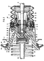
- the vacuum housing of the brake booster consists of two housing parts launched at a connection point, of which, for the sake of clarity, only the housing half 7 on the brake pedal side is partially shown.
- the interior of the vacuum housing is divided by a booster piston 19 into a vacuum chamber 20, which is connected via a vacuum connection to a vacuum source (not shown in more detail), and a working chamber 23.
- the booster piston 19 has a rolling diaphragm 18 resting thereon in the working chamber 23 and a two-part control valve housing 10 connected to the booster piston 19 and the rolling diaphragm 18.
- the roller membrane 18 is clamped pressure-tight at the connection point 26 and engages with its inner portion around the inner edge 43 of the booster piston 19 and seals it against the front part of the control valve housing.
- the control valve housing 10 projects with its cylindrical guide part 4 out of the booster housing and is protected against contamination of its surface by means of a bellows 27.
- the control valve housing 10 seals the working chamber 23 from the outside with a sliding guide ring 5.
- a control rod composed of piston rod 13 and valve piston 16 is arranged so as to be axially displaceable, which does not have one Clevis shown in detail can be connected to a brake pedal of a motor vehicle.
- the control valve housing 10 also contains a valve arrangement 1, 9, 12 which is actuated by the valve piston 16 and controls the pressure difference between the vacuum chamber 20 and the working chamber 23 via channels 36, 37.
- the front part 2 of the control valve housing 10 arranged in the vacuum chamber 20 also has an axial bore 3, the task of which is described below.
- a push rod 29 actuates a master brake cylinder, not shown in more detail, attached to the front of the bottom of the booster housing.
- a guide sleeve 14 is provided, the axial extension 22 of which is inserted into the axial bore 3 of the front part 2 and the guidance of a reaction disc 30 arranged therein and one between the reaction disc 30 and the end of the pressure rod 29 on the control housing side provided pressure plate 17 is used.
- a metallic translation ring 33 is partially encompassed, in the bore of which a translation disk 6 is arranged, which cooperates with the control valve piston 16 and whose surface in contact with the reaction disk 30 with the annular end face of the translation ring 33 is the translation of Vacuum brake booster according to the invention determined.
- the guide sleeve 14 secured by a retaining ring 31 is sealed by means of a sealing ring 34 which is arranged in the radial gap between the surface of the transmission ring 33 and the wall of the axial bore 3.
- the retaining ring 31, the Starting material is preferably identical to that of the front part 2 of the control valve housing 10, is arranged in the radial recess 21 and welded to it by means of ultrasound.
- a return spring 25 is provided, which is clamped between the front part 2 of the control valve housing 10 and the bottom of the booster housing.
- the control assembly of the vacuum brake booster is shown in the release position, ie in a position in which the two chambers 20, 23 are separated from one another.
- the two sealing seats 9, 12 rest on the sealing surface of a poppet valve 1, which has a stop 8 on its side facing away from the sealing surface, which stops via a sleeve 38 in the guide part 4.
- the guide part 4 lies in the release position with its collar 28 on the sliding guide ring 5, the sealing seat 9 on the control valve piston 16 being pressed against the sealing surface of the poppet valve 1 by a piston rod return spring 11.
- the poppet valve 1 is simultaneously biased towards the two sealing seats 9, 12 by means of a compression spring 15, which is supported at the other end on the sleeve 38.
- a second compression spring 39 is provided, which is supported on the one hand on a guide 40 of the poppet valve 1 and on the other hand on an annular surface 41 of the sleeve 38 and keeps the two control valve housing parts 2, 4 apart.
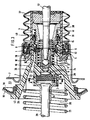
- the transmission ring 33 (FIG. 1) is replaced by a radial annular surface 28 formed in the front part 2 of the control valve housing 10, which is provided on the one hand by a bore 24 receiving the transmission disk 6 and on the other hand by an axial recess 32 is limited.
- the end of the axial extension 22 engages in this recess 32, the sealing of the axial extension 3 being taken over by the reaction disk 30.
- the axial extension 22 of the guide sleeve 14 is designed so that it has an excess compared to the diameter of the axial bore 3 of the front part 2, so that the axial extension 22 at the Assembly of the guide sleeve 14 is pressed non-positively into the axial bore 3.
- the wall of the axial bore is preferably provided with axial ribs 35, which allow greater elastic expansion during assembly.
- the axial ribs 35 are then expediently to be arranged between the outer stiffening ribs 42 of the front part 2 of the control valve housing 10.
Description
Die Erfindung betrifft einen Vakuumbremskraftverstärker für Kraftfahrzeuge, mit einem Unterdruckgehäuse, das durch eine axial bewegliche Wand in eine Unterdruckkammer und eine Arbeitskammer dichtend unterteilt ist, mit einem mechanisch betätigbaren Steuerventil zur Verbindung der Arbeitskammer mit der Unterdruckkammer bzw. mit der Atmosphäre, dessen axial bewegliches Steuerventilgehäuse aus thermoplastischem Kunststoff ausgebildet ist und in einer axialen Bohrung eine gummielastische Reaktionsscheibe aufnimmt, die an einer Druckplatte einer Druckstange anliegt, die die Bremskraft auf einen Betätigungskolben eines unterdruckseitig am Unterdruckgehäuse angebrachten Hauptzylinders überträgt, wobei die bewegliche Wand mit dem Steuerventilgehäuse verbunden ist und eine der axialen Führung der Druckstange dienende, einen radialen Flansch aufweisende Führungshülse vorgesehen ist.The invention relates to a vacuum brake booster for motor vehicles, with a vacuum housing which is sealingly divided by an axially movable wall into a vacuum chamber and a working chamber, with a mechanically actuable control valve for connecting the working chamber to the vacuum chamber or to the atmosphere, the axially movable control valve housing is made of thermoplastic material and receives in an axial bore a rubber-elastic reaction disc, which rests on a pressure plate of a pressure rod, which transmits the braking force to an actuating piston of a master cylinder attached to the vacuum side of the vacuum housing, the movable wall being connected to the control valve housing and one of the axial Guide the push rod serving, a radial flange guide sleeve is provided.
Ein derartiger Vakuumbremskraftverstärker ist aus der älteren Anmeldung der Anmelderin, siehe Dokument DE-A1-3709172.7 bekannt. Das Besondere an diesem Bremskraftverstärker besteht darin, (veroffentlicht am 29.09.88) daß der radiale Flansch der Führungshülse innerhalb der Bohrung des Steuerventilgehäuses axial abgestützt ist und von einem mit dem Steuerventilghehäuse in Verbindung stehenden Halteteil axial formschlüssig umgriffen wird.Such a vacuum brake booster is known from the applicant's earlier application, see document DE-A1-3709172.7. The special thing about this brake booster is that (published on 29.09.88) that the radial flange of the guide sleeve is axially supported within the bore of the control valve housing and is axially positively encompassed by a holding part which is connected to the control valve housing.
Weniger vorteilhaft anzusehen ist bei dem oben erwähnten Bremskraftverstärker die starke Belastung des Steuerventilgehäuses im Bereich der Abstützung des radialen Flansches der Führungshülse beim Auftreten von auf die Druckstange wirkenden Querkräften, die eine Gefahr der Beschädigung des in diesem Bereich dünnwandig ausgebildeten Steuerventilgehäuses mit sich bringt.In the case of the brake booster mentioned above, the load on the control valve housing in the region of the support of the radial flange of the guide sleeve when transverse forces acting on the push rod occur is less advantageous, which entails a risk of damage to the control valve housing, which is thin-walled in this region.
Es ist daher Aufgabe der vorliegenden Erfindung einen Vakuumbremskraftverstärker der eingangs genanten Gattung anzugeben, bei dem die oben erwähnte Beschädigungsgefahr weitgehendst vermieden wird.It is therefore an object of the present invention to provide a vacuum brake booster of the type mentioned at the outset, in which the risk of damage mentioned above is largely avoided.
Diese Aufgabe wird dadurch gelöst, daß die Führungshülse einen axialen Fortsatz aufweist, der, die Druckplatte sowie die Reaktionsscheibe aufnehmend, in der axialen Bohrung des Steuerventilgehäuses abgedichtet angeordnet ist.This object is achieved in that the guide sleeve has an axial extension which, receiving the pressure plate and the reaction disk, is arranged in a sealed manner in the axial bore of the control valve housing.
Es wird also ein Vakuumbremskraftverstärker für Kraftfahrzeuge geschaffen, bei dem eine erhebliche Erhöhung der Funktionssicherheit unter Verwendung von kostengünstigen Einzelteilen erreicht wird. Gleichzeitig wird durch die erfindungsgemäße Ausbildung des Bremskraftverstärkers eine hervorragende Führung der Druckstange gewährleistet. Außerdem bietet diese Maßnahme einen wirksamen Schutz des Kunststoff-Steuerventilgehäuses vor den hohen Drücken in der Reaktionsscheibe.A vacuum brake booster for motor vehicles is thus created, in which a considerable increase in functional reliability is achieved using inexpensive individual parts. At the same time, the inventive design of the brake booster ensures excellent guidance of the push rod. In addition, this measure offers effective protection of the plastic control valve housing against the high pressures in the reaction disk.
Eine vorteilhafte Weiterbildung des Erfindungsgegenstandes sieht vor, daß die Führungshülse in der axialen Bohrung mittels eines Halteringes gehalten wird, der in einer an druckstangenseitigem Ende der Bohrung ausgebildeten radialen Ausnehmung angeordnet ist, wobei der Ausgangswerkstoff des Halteringes dem des Steuerventilgehäuses entspricht und dessen Verbindung mit dem Steuerventilgehäuse durch Ultraschallverschweißen erfolgt. Durch diese Maßnahme wird eine höhere Festigkeit der Verbindung der Druckstange mit dem Steuerventilgehäuse erreicht, die vor allem bei Bremskraftverstärkern größeren Durchmesser wichtig ist.An advantageous development of the subject matter of the invention provides that the guide sleeve is held in the axial bore by means of a retaining ring which is arranged in a radial recess formed at the end of the bore on the push rod side, the starting material of the retaining ring corresponding to that of the control valve housing and its connection to the control valve housing done by ultrasonic welding. This measure achieves a higher strength of the connection of the push rod with the control valve housing, which is particularly important in the case of brake boosters of larger diameter.
Eine vorteilhafte Vereinfachung des Erfindungsgegenstandes wird dadurch erreicht, daß der axiale Fortsatz der Führungshülse gegenüber dem Durchmesser der axialen Bohrung ein Übermaß aufweist, so daß die beiden Teile mittels eines Preßsitzes verbunden sind, wobei die Wandung der axialen Bohrung mit axialen Rippen versehen sein kann, um die elastische Verformung besser aufzunehmen.An advantageous simplification of the subject matter of the invention is achieved in that the axial extension of the guide sleeve has an excess compared to the diameter of the axial bore, so that the two parts are connected by means of an interference fit, the wall of the axial bore being able to be provided with axial ribs in order to better absorb the elastic deformation.
Um die Verwendung des Steuerventilgehäuses für alle gewünschten Übersetzungen des Verstärkers zu ermöglichen wird nach einem weiteren Merkmal der Erfindung vorgesehen, daß der axiale Fortsatz der Führungshülse einen eine zwischen dem Steuerventilkolben und der Reaktionsscheibe angeordnete Übersetzungsscheibe führenden metallischen Übersetzungsring teilweise umgreift, der sich einerseits an der Reaktionsscheibe und andererseits am Boden der axialen Bohrung abstützt, wobei die Abdichtung des axialen Fortsatzes gegenüber dem Steuerventilgehäuse mittels eines Dichtringes erfolgt, der zwischen der Wandung der axialen Bohrung und der radial außen liegenden Oberfläche des Übersetzungsringes angeordnet ist. Diese Maßnahme ermöglicht es, das zwischen der Übersetzungsscheibe und dem Übersetzungsring vorhandene radiale Spiel möglichst gering zu halten, so daß die Gefahr einer Beschädigung der unter hohem Druck stehenden Reaktionsscheibe in diesem Bereich vermieden wird.In order to enable the use of the control valve housing for all desired translations of the amplifier, it is provided according to a further feature of the invention that the axial extension of the guide sleeve partially engages around a metal translation ring which is arranged between the control valve piston and the reaction disk and which, on the one hand, engages on the reaction disk and, on the other hand, is supported on the bottom of the axial bore, the axial extension being sealed off from the control valve housing by means of a sealing ring which is located between the wall of the axial Bore and the radially outer surface of the transmission ring is arranged. This measure makes it possible to keep the radial play between the translation disk and the translation ring as small as possible, so that the risk of damage to the reaction disk under high pressure is avoided in this area.
Eine weitere Vereinfachung des erfindungsgemäßen Bremskraftverstärkers wird nach einer vorteilhaften Weiterbildung dadurch erreicht, daß der axiale Fortsatz in eine axiale Ausnehmung eingreift, die im Steuerventilgehäuse eine radiale Ringfläche begrenzt, deren Größe die Übersetzung des Brmeakraftverstärker bestimmt, wobei die Abdichtung des axialen Fortsatzes gegenüber dem Steuerventilgehäuse mittels der Reaktionsscheibe erfolgt.A further simplification of the brake booster according to the invention is achieved according to an advantageous development in that the axial extension engages in an axial recess which delimits a radial annular surface in the control valve housing, the size of which determines the ratio of the brake booster, the sealing of the axial extension relative to the control valve housing by means of the reaction disc takes place.
Weitere Einzelheiten und Vorteile des erfindungsgemäßen Vakuumbremskraftverstärkers ergeben sich aus der nachfolgenden Beschreibung von drei Ausführungsbeispielen der Erfindung, die anhand der beiliegenden Zeichnung näher erläutert sind, wobei die einander entsprechenden Teile mit den gleichen Bezugszeichen versehen sind.Further details and advantages of the vacuum brake booster according to the invention result from the following description of three exemplary embodiments of the invention, which are explained in more detail with reference to the accompanying drawing, the corresponding parts being provided with the same reference numerals.
Es zeigt
- Fig. 1
- einen Teil-Längsschnitt einer ersten Ausführung des Vakuumbremskraftverstärkers nach der Erfindung;
- Fig. 2
- einen Teil-Längsschnitt einer zweiten Ausführung des Vakuumbremskraftverstärkers nach der Erfindung;
- Fig. 3
- einen Teil-Längsschnitt einer dritten Ausführung des Vakuumbremskraftverstärkers nach der Erfindung und
- Fig. 4
- den Schnitt A-A nach Fig. 3
It shows
- Fig. 1
- a partial longitudinal section of a first embodiment of the vacuum brake booster according to the invention;
- Fig. 2
- a partial longitudinal section of a second embodiment of the vacuum brake booster according to the invention;
- Fig. 3
- a partial longitudinal section of a third embodiment of the vacuum brake booster according to the invention and
- Fig. 4
- the section AA of FIG. 3rd
Das Unterdruckgehäuse des Bremskraftverstärkers besteht aus zwei an einer Verbindungsstelle miteinander lancierten Gehäuseteilen, von denen, der besseren Übersichtlichkeit wegen, nur die bremspedalseitige Gehäusehälfte 7 teilweise dargestellt ist. Der Innenraum des Unterdruckgehäuses wird durch einen Verstärkerkolben 19 in eine Unterdruckkammer 20, die über einen Vakuumanschluß mit einer Vakuumquelle verbunden ist (nicht näher dargestellt), und eine Arbeitskammer 23 unterteilt. Der Verstärkerkolben 19 weist eine in der Arbeitskammer 23 daran anliegende Rollmembran 18 und ein mit dem Verstärkerkolben 19 und der Rollmembran 18 verbundenes, zweiteilig ausgebildetes Steuerventilgehäuse 10 auf. Die Rollmembran 18 ist an der Verbindungsstelle 26 druckdicht eingespannt und umgreift mit ihrem inneren Abschnitt den Innenrand 43 des Verstärkerkolbens 19 und dichtet diesen gegenüber dem vorderen Teil des Steuerventilgehäuses ab. Das Steuerventilgehäuse 10 ragt mit seinem zylindrischen Führungsteil 4 aus dem Verstärkergehäuse heraus und wird mittels eines Faltenbalges 27 gegen Verschmutzung seiner Oberfläche geschützt. Das Steuerventilgehäuse 10 dichtet mit einem Gleitführungsring 5 die Arbeitskammer 23 nach außen hin ab.The vacuum housing of the brake booster consists of two housing parts launched at a connection point, of which, for the sake of clarity, only the housing half 7 on the brake pedal side is partially shown. The interior of the vacuum housing is divided by a
Im Inneren des Steuerventilgehäuses 10 ist eine aus Kolbenstange 13 und Ventilkolben 16 zusammengesetzte Steuerstange axial verschiebbar angeordnet, die über einen nicht näher dargestellten Gabelkopf mit einem Bremspedal eines Kraftfahrzeuges verbindbar ist. Das Steuerventilgehäuse 10 enthält ferner eine Ventilanordnung 1, 9, 12, die von dem Ventilkolben 16 betätigt wird und über Kanäle 36, 37 die Druckdifferenz zwischen Unterdruckkammer 20 und Arbeitskammer 23 steuert. Der in der Unterdruckkammer 20 angeordnete Vorderteil 2 des Steuerventilgehäuses 10 weist ferner eine axiale Bohrung 3 auf, deren Aufgabe nachfolgend beschrieben ist. Eine Druckstange 29 betätigt einen an der Stirnseite des Bodens des Verstärkergehäuses befestigten, nicht näher dargestellten Hauptbremszylinder.In the interior of the
Um eine präzise Führung der Druckstange 29 zu erzielen ist eine Führungshülse 14 vorgesehen, deren axialer Fortsatz 22 in die axiale Bohrung 3 des Vorderteiles 2 eingeführt ist und der Führung einer darin angeordneten Reaktionsscheibe 30 sowie einer zwischen der Reaktionsscheibe 30 und dem steuergehäuseseitigen Ende der Druckstange 29 vorgesehenen Druckplatte 17 dient. Vom axialen Fortsatz 22 der Führungshülse 14 wird teilweise ein metallischer Übersetzungsring 33 umgriffen, in dessen Bohrung eine Übersetzungscheibe 6 angeordnet ist, die mit dem Steuerventilkolben 16 zusammenwirkt und deren mit der Reaktionsscheibe 30 in Berührung stehende Fläche mit der ringförmigen Stirnfläche des Übersetzungsringes 33 die Übersetzung des erfindungsgemäßen Vakuumbremskraftverstärkers bestimmt. Gegenüber dem Vorderteil 2 des Steuerventilgehäuses 10 bzw. dessen axialer Bohrung 3 ist die durch einen Haltering 31 gesicherte Führungshülse 14 mittels eines Dichtringes 34 abgedichtet, der im radialen Spalt zwischen der Oberfläche des Übersetzungsringes 33 und der Wandung der axialen Bohrung 3 angeordnet ist. Der Haltering 31, dessen Ausgangswerkstoff vorzugsweise mit dem des Vorderteiles 2 des Steuerventilgehäuses 10 identisch ist, ist in dessen radialer Ausnehmung 21 angeordnet und mit ihm mittels Ultraschall verschweißt.In order to achieve a precise guidance of the
Zum Zurückstellen des Verstärkerkolbens 19 ist eine Rückstellfeder 25 vorgesehen, die zwischen dem Vorderteil 2 des Steuerventilgehäuses 10 und dem Boden des Verstärkergehäuses eingespannt ist.To reset the
Die Steuerbaugruppe des Vakuumbremskraftverstärkers ist in der Lösestellung dargestellt, d.h. in einer Stellung, in der die beiden Kammern 20, 23 voneinander getrennt sind. In dieser Stellung liegen nämlich die beiden Dichtsitze 9, 12 an der Dichtfläche eines Tellerventils 1 an, das auf seiner der Dichtfläche abgewandten Seite einen Anschlag 8 aufweist, der über eine Hülse 38 im Führungsteil 4 anschlägt. Das Führungsteil 4 liegt in der Lösestellung mit seinem Kragen 28 am Gleitführungsring 5 an, wobei der Dichtsitz 9 am Steuerventilkolben 16 von einer Kolbenstangenrückholfeder 11 gegen die Dichtfläche des Tellerventils 1 gedrückt wird. Das Tellerventil 1 wird gleichzeitig in Richtung auf die beiden Dichtsitze 9, 12 zu mittels einer Druckfeder 15 vorgespannt, die sich mit deren anderem Ende an der Hülse 38 abstützt. Außerdem ist eine zweite Druckfeder 39 vorgesehen, die sich einerseits an einer Führung 40 des Tellerventils 1 und andererseits an einer ringförmigen Fläche 41 der Hülse 38 abstützt und die beiden Steuerventilgehäuseteile 2, 4 auseinander hält.The control assembly of the vacuum brake booster is shown in the release position, ie in a position in which the two
Bei der in Fig. 2 gezeigten Ausführungsform des Erfidungsgegenstandes wird der Übersetzungsring 33 (Fig. 1) durch eine im Vorderteil 2 des Steuerventilgehäuses 10 ausgebildete radiale Ringfläche 28 ersetzt, die einerseits durch eine die Übersetzungsscheibe 6 aufnehmende Bohrung 24 und andererseits durch eine axiale Ausnehmung 32 begrenzt ist. In diese Ausnehmung 32 greift das Ende des axialen Fortsatzes 22 hinein, wobei dessen Abdichtung gegenüber der axialen Bohrung 3 von der Reaktionsscheibe 30 übernommen wird.In the embodiment of the subject matter shown in FIG. 2, the transmission ring 33 (FIG. 1) is replaced by a radial
Eine ähnliche Anordnung zeigen schließlich die Fig. 3 und 4. Bei diesem Ausführungsbeispiel ist der axiale Fortsatz 22 der Führungshülse 14 so ausgebildet, daß er gegenüber dem Durchmesser der axialen Bohrung 3 des Vorderteiles 2 ein Übermaß aufweist, so daß der axiale Fortsatz 22 bei der Montage der Führungshülse 14 in die axiale Bohrung 3 kraftschlüssig eingepreßt wird. Die Wandung der axialen Bohrung ist dabei vorzugsweise mit axialen Rippen 35 versehen, die eine größere elastische Dehnung bei der Montage ermöglichen. Die axialen Rippen 35 sind dann sinnvollerweise zwischen den äußeren Versteifungsrippen 42 des Vorderteiles 2 des Steuerventilgehäuses 10 anzuordnen.3 and 4. Finally, a similar arrangement is shown in FIGS. 3 and 4. In this embodiment, the
- 1 Tellerventil1 poppet valve
- 2 Vorderteil2 front part
- 3 Bohrung3 hole
- 4 Führungsteil4 guide part
- 5 Gleitführungsring5 sliding guide ring
- 6 Übersetzungsscheibe6 transmission disc
- 7 Verstärkergehäusehälfte7 amplifier housing half
- 8 Anschlagfläche8 stop surface
- 9 Dichtsitz9 sealing seat
- 10 Steuerventilgehäuse10 control valve housing
- 11 Feder11 spring
- 12 Dichtsitz12 sealing seat
- 13 Kolbenstange13 piston rod
- 14 Führungshülse14 guide sleeve
- 15 Feder15 spring
- 16 Steuerventilkolben16 control valve pistons
- 17 Druckplatte17 pressure plate
- 18 Rollmembran18 roll membrane
- 19 Verstärkerkolben19 booster pistons
- 20 Unterdruckkammer20 vacuum chamber
- 21 Ausnehmung21 recess
- 22 Fortsatz22 continuation
- 23 Arbeitskammer23 Chamber of Labor
- 24 Bohrung24 hole
- 25 Rückstellfeder25 return spring
- 26 Verbindungsstelle26 connection point
- 27 Faltenbalg27 bellows
- 28 Ringfläche28 ring surface
- 29 Druckstange29 push rod
- 30 Reaktionsscheibe30 reaction disc
- 31 Haltering31 retaining ring
- 32 Ausnehmung32 recess
- 33 Übersetzungsring33 transmission ring
- 34 Dichtring34 sealing ring
- 35 axiale Rippen35 axial ribs
- 36 Kanal36 channel
- 37 Kanal37 channel
- 38 Hülse38 sleeve
- 39 Druckfeder39 compression spring
- 40 Führung40 leadership
- 41 Fläche41 area
- 42 äußere Versteifungsrippen42 outer stiffening ribs
- 43 Innenwand43 inner wall
Claims (11)
Applications Claiming Priority (2)
| Application Number | Priority Date | Filing Date | Title |
|---|---|---|---|
| DE19873740691 DE3740691A1 (en) | 1987-12-01 | 1987-12-01 | VACUUM BRAKE POWER AMPLIFIER FOR MOTOR VEHICLES |
| DE3740691 | 1987-12-01 |
Publications (2)
| Publication Number | Publication Date |
|---|---|
| EP0318681A1 EP0318681A1 (en) | 1989-06-07 |
| EP0318681B1 true EP0318681B1 (en) | 1991-08-14 |
Family
ID=6341651
Family Applications (1)
| Application Number | Title | Priority Date | Filing Date |
|---|---|---|---|
| EP88117006A Expired - Lifetime EP0318681B1 (en) | 1987-12-01 | 1988-10-13 | Vacuum servo brake for motor vehicles |
Country Status (4)
| Country | Link |
|---|---|
| US (1) | US4898073A (en) |
| EP (1) | EP0318681B1 (en) |
| DE (2) | DE3740691A1 (en) |
| ES (1) | ES2023998B3 (en) |
Families Citing this family (16)
| Publication number | Priority date | Publication date | Assignee | Title |
|---|---|---|---|---|
| DE3930240A1 (en) * | 1988-10-22 | 1990-04-26 | Teves Gmbh Alfred | Vacuum operated brake servo - has thrust rod located in support sleeve to reduce risk of damage to valve |
| DE3904641A1 (en) * | 1989-02-16 | 1990-08-23 | Teves Gmbh Alfred | VACUUM BRAKE POWER AMPLIFIER |
| DE4014560A1 (en) * | 1990-05-07 | 1991-11-14 | Teves Gmbh Alfred | Negative pressure vehicle braking force booster - has provision of air guidance channels to minimise noise generation during braking |
| DE4032534A1 (en) * | 1990-10-13 | 1992-04-16 | Teves Gmbh Alfred | Negative pressure booster for vehicle braking system - makes use of U=shaped component with rubber spring layers attached |
| FR2690666B1 (en) * | 1992-04-30 | 1994-06-24 | Bendix Europ Services Tech | IMPROVED POWER TRANSMISSION DEVICE FOR SERVOMOTOR. |
| FR2691691B1 (en) * | 1992-05-26 | 1996-08-09 | Bendix Europ Services Tech | PNEUMATIC SERVOMOTOR. |
| KR950000490A (en) * | 1993-01-26 | 1995-01-03 | 시시도 도시마사 | Valve body holding structure and valve body holding cylinder attachment structure in negative pressure booster |
| DE4408993C2 (en) * | 1994-03-16 | 1997-05-07 | Lucas Ind Plc | Actuator assembly for a motor vehicle brake system |
| JP3131094B2 (en) * | 1994-05-25 | 2001-01-31 | アイシン精機株式会社 | Negative pressure booster |
| FR2724356B1 (en) * | 1994-09-08 | 1997-01-10 | Alliedsignal Europ Services | PNEUMATIC BRAKE SUPPORT SERVOMOTOR |
| JP3350684B2 (en) * | 1994-10-14 | 2002-11-25 | 株式会社ボッシュオートモーティブシステム | Booster |
| US6003425A (en) * | 1998-03-27 | 1999-12-21 | Jidosha Kiki Co., Ltd. | Booster |
| JP4366733B2 (en) * | 1998-10-02 | 2009-11-18 | ボッシュ株式会社 | Brake booster |
| US6327958B1 (en) * | 2000-07-31 | 2001-12-11 | Robert Bosch Corporation | Brake booster and its method of assembly |
| US8640599B2 (en) | 2010-06-15 | 2014-02-04 | Robert Bosch Gmbh | Brake booster having atmosphere chamber void of springs |
| CN103419766B (en) * | 2013-08-07 | 2015-06-24 | 京西重工(上海)有限公司 | Vacuum booster reaction rod retaining appliance and reaction rod retaining method |
Family Cites Families (10)
| Publication number | Priority date | Publication date | Assignee | Title |
|---|---|---|---|---|
| JPS54142783U (en) * | 1978-03-29 | 1979-10-03 | ||
| DE2908516A1 (en) * | 1979-03-05 | 1980-10-16 | Teves Gmbh Alfred | BRAKE POWER AMPLIFIER FOR A MOTOR VEHICLE |
| JPS56127048U (en) * | 1980-02-27 | 1981-09-28 | ||
| DE3111188A1 (en) * | 1981-03-21 | 1982-09-30 | Alfred Teves Gmbh, 6000 Frankfurt | MECHANICALLY CONTROLLABLE POWER AMPLIFIER, ESPECIALLY FOR BRAKE SYSTEMS OF MOTOR VEHICLES |
| DE3232664A1 (en) * | 1982-09-02 | 1984-03-08 | Lucas Industries P.L.C., Birmingham, West Midlands | Power amplifier, in particular for actuating the brakes of vehicles |
| US4587885A (en) * | 1983-09-09 | 1986-05-13 | Itt Industries, Inc. | Vacuum-operated brake power booster |
| DE3344110A1 (en) * | 1983-12-07 | 1985-06-13 | Alfred Teves Gmbh, 6000 Frankfurt | Vacuum brake booster |
| US4671167A (en) * | 1984-03-19 | 1987-06-09 | Tokico Ltd. | Pneumatic booster |
| DE3411027C2 (en) * | 1984-03-24 | 1996-04-25 | Teves Gmbh Alfred | Vacuum brake booster |
| JPS616058A (en) * | 1984-06-05 | 1986-01-11 | ルーカス・インダストリーズ・パブリツク・リミテツド・カンパニー | Pneumatic pressure booster |
-
1987
- 1987-12-01 DE DE19873740691 patent/DE3740691A1/en not_active Withdrawn
-
1988
- 1988-10-13 ES ES88117006T patent/ES2023998B3/en not_active Expired - Lifetime
- 1988-10-13 EP EP88117006A patent/EP0318681B1/en not_active Expired - Lifetime
- 1988-10-13 DE DE8888117006T patent/DE3864241D1/en not_active Expired - Lifetime
- 1988-11-29 US US07/277,288 patent/US4898073A/en not_active Expired - Fee Related
Non-Patent Citations (1)
| Title |
|---|
| PATENT ABSTRACTS OF JAPAN, band 7, Nr. 55, (M198)(1200), 5. März 1983 * |
Also Published As
| Publication number | Publication date |
|---|---|
| ES2023998B3 (en) | 1992-02-16 |
| DE3740691A1 (en) | 1989-06-15 |
| DE3864241D1 (en) | 1991-09-19 |
| US4898073A (en) | 1990-02-06 |
| EP0318681A1 (en) | 1989-06-07 |
Similar Documents
| Publication | Publication Date | Title |
|---|---|---|
| EP0318681B1 (en) | Vacuum servo brake for motor vehicles | |
| EP0734927B1 (en) | Electrically controllable brake system for land vehicles and procedure for its operation | |
| DE2602050C3 (en) | Hydraulic booster valve, in particular for a hydraulic brake system of a motor vehicle | |
| DE3709172A1 (en) | VACUUM BRAKE POWER AMPLIFIER FOR MOTOR VEHICLES AND METHOD FOR THE PRODUCTION THEREOF | |
| DE2208755C2 (en) | Diaphragm fastening for brake boosters | |
| EP0420947B1 (en) | Vacuum brake booster for motor vehicles | |
| EP0347583A2 (en) | Vacuum motor for brake installations in vehicles | |
| EP0383050B1 (en) | Vacuum servo brake | |
| DE3101795A1 (en) | PNEUMATIC SERVO BOOSTER | |
| EP0886595B1 (en) | Pneumatic brake booster | |
| EP0166985B1 (en) | Pneumatic power booster, particularly for brake installations of motor vehicles | |
| EP0322524B1 (en) | Tandem servo brake for motor vehicles | |
| DE3318744C2 (en) | ||
| DE2014236B2 (en) | Brake booster for vehicles | |
| EP0681539B1 (en) | Vacuum power brake for motor vehicles | |
| EP0847353B1 (en) | Pneumatic servobrake | |
| DE3107918A1 (en) | Mechanically controllable power amplifier, in particular for hydraulic motor-vehicle brake systems | |
| DE60013522T2 (en) | Vacuum booster | |
| DE3407350A1 (en) | VACUUM-POWERED BRAKE-AMPLIFIER | |
| EP0326965A2 (en) | Control device for vehicle brake systems | |
| DE3939499A1 (en) | Vehicle brake vacuum servo - has elastomeric reaction disc with face of master cylinder control rod flange, formed with axial recess | |
| DE69619351T3 (en) | Actuating cylinder of a hydraulic clutch of a vehicle | |
| DE3518288C2 (en) | Brake pressure sensor with a vacuum-operated brake booster and a master cylinder | |
| DE3930240A1 (en) | Vacuum operated brake servo - has thrust rod located in support sleeve to reduce risk of damage to valve | |
| DE19539601B4 (en) | Vacuum brake booster for motor vehicles |
Legal Events
| Date | Code | Title | Description |
|---|---|---|---|
| PUAI | Public reference made under article 153(3) epc to a published international application that has entered the european phase |
Free format text: ORIGINAL CODE: 0009012 |
|
| 17P | Request for examination filed |
Effective date: 19881013 |
|
| AK | Designated contracting states |
Kind code of ref document: A1 Designated state(s): DE ES FR GB IT |
|
| 17Q | First examination report despatched |
Effective date: 19901112 |
|
| ITF | It: translation for a ep patent filed |
Owner name: DE DOMINICIS & MAYER S.R.L. |
|
| GRAA | (expected) grant |
Free format text: ORIGINAL CODE: 0009210 |
|
| AK | Designated contracting states |
Kind code of ref document: B1 Designated state(s): DE ES FR GB IT |
|
| REF | Corresponds to: |
Ref document number: 3864241 Country of ref document: DE Date of ref document: 19910919 |
|
| GBT | Gb: translation of ep patent filed (gb section 77(6)(a)/1977) | ||
| ET | Fr: translation filed | ||
| REG | Reference to a national code |
Ref country code: ES Ref legal event code: FG2A Ref document number: 2023998 Country of ref document: ES Kind code of ref document: B3 |
|
| PGFP | Annual fee paid to national office [announced via postgrant information from national office to epo] |
Ref country code: DE Payment date: 19920218 Year of fee payment: 4 |
|
| PLBE | No opposition filed within time limit |
Free format text: ORIGINAL CODE: 0009261 |
|
| STAA | Information on the status of an ep patent application or granted ep patent |
Free format text: STATUS: NO OPPOSITION FILED WITHIN TIME LIMIT |
|
| 26N | No opposition filed | ||
| PGFP | Annual fee paid to national office [announced via postgrant information from national office to epo] |
Ref country code: GB Payment date: 19920928 Year of fee payment: 5 |
|
| PGFP | Annual fee paid to national office [announced via postgrant information from national office to epo] |
Ref country code: FR Payment date: 19921006 Year of fee payment: 5 |
|
| PGFP | Annual fee paid to national office [announced via postgrant information from national office to epo] |
Ref country code: ES Payment date: 19921013 Year of fee payment: 5 |
|
| PG25 | Lapsed in a contracting state [announced via postgrant information from national office to epo] |
Ref country code: DE Effective date: 19930701 |
|
| PG25 | Lapsed in a contracting state [announced via postgrant information from national office to epo] |
Ref country code: GB Effective date: 19931013 |
|
| PG25 | Lapsed in a contracting state [announced via postgrant information from national office to epo] |
Ref country code: ES Free format text: LAPSE BECAUSE OF NON-PAYMENT OF DUE FEES Effective date: 19931014 |
|
| GBPC | Gb: european patent ceased through non-payment of renewal fee |
Effective date: 19931013 |
|
| PG25 | Lapsed in a contracting state [announced via postgrant information from national office to epo] |
Ref country code: FR Effective date: 19940630 |
|
| REG | Reference to a national code |
Ref country code: FR Ref legal event code: ST |
|
| REG | Reference to a national code |
Ref country code: ES Ref legal event code: FD2A Effective date: 19990503 |
|
| PG25 | Lapsed in a contracting state [announced via postgrant information from national office to epo] |
Ref country code: IT Free format text: LAPSE BECAUSE OF NON-PAYMENT OF DUE FEES;WARNING: LAPSES OF ITALIAN PATENTS WITH EFFECTIVE DATE BEFORE 2007 MAY HAVE OCCURRED AT ANY TIME BEFORE 2007. THE CORRECT EFFECTIVE DATE MAY BE DIFFERENT FROM THE ONE RECORDED. Effective date: 20051013 |