EP0318641A2 - Verfahren und Vorrichtung zur Übertragung thermischer Energie auf bzw. von einem plattenförmigen Substrat - Google Patents
Verfahren und Vorrichtung zur Übertragung thermischer Energie auf bzw. von einem plattenförmigen Substrat Download PDFInfo
- Publication number
- EP0318641A2 EP0318641A2 EP88112869A EP88112869A EP0318641A2 EP 0318641 A2 EP0318641 A2 EP 0318641A2 EP 88112869 A EP88112869 A EP 88112869A EP 88112869 A EP88112869 A EP 88112869A EP 0318641 A2 EP0318641 A2 EP 0318641A2
- Authority
- EP
- European Patent Office
- Prior art keywords
- plate
- gas
- carrier device
- lid
- cover
- Prior art date
- Legal status (The legal status is an assumption and is not a legal conclusion. Google has not performed a legal analysis and makes no representation as to the accuracy of the status listed.)
- Granted
Links
Images
Classifications
-
- H—ELECTRICITY
- H10—SEMICONDUCTOR DEVICES; ELECTRIC SOLID-STATE DEVICES NOT OTHERWISE PROVIDED FOR
- H10P—GENERIC PROCESSES OR APPARATUS FOR THE MANUFACTURE OR TREATMENT OF DEVICES COVERED BY CLASS H10
- H10P72/00—Handling or holding of wafers, substrates or devices during manufacture or treatment thereof
- H10P72/04—Apparatus for manufacture or treatment
- H10P72/0431—Apparatus for thermal treatment
- H10P72/0434—Apparatus for thermal treatment mainly by convection
Definitions
- the invention relates to a device for achieving heat transfer between a plate-shaped object and a carrier device.
- It relates in particular to a device for transferring thermal energy between the carrier and the wafer, in which a gas is introduced between the wafer and the carrier device in order to improve this transfer of heat, and in which the same gas serves to press the wafer on the carrier device.
- the smallest possible distance between the plate and the back plate is maintained by the protrusion.
- the disadvantage of this invention is that such curvature of the platelet, for example for silicon wafers with a diameter of> 4 ⁇ , must not be accepted, since it leads to the risk of breakage, stress conditions in the layer and tolerance problems in the microstructure of the finished products.
- the object of the invention is therefore to take full advantage of the heat transfer through the gas line for the transfer of heat between the backplate and the plate and to avoid the disadvantages of a mechanical load due to bulging and preloading of the plate.
- a gas is also used as a so-called gas cushion to improve the heat transfer between plate and back plate as to press the wafer on this back plate while avoiding mechanical loading of the same. Since the gap between the plate and the back plate remains small, the thermal resistance is reduced and the heat transfer is improved.
- the back plate 1 is anchored in the base plate 2.
- This back plate has a temperature different from the temperature of the plate-shaped object 5, for example a silicon wafer, and can therefore be designed as a heating or cooling plate depending on the task.
- the platelet 5 rests on this back plate 1, whereby in the case of a silicon wafer, due to the grain size of the two materials, only small areas of the two surfaces (typically less than 5%) are actually in contact with one another and an intermediate space is formed between them, in which a Hole 3 a gas can be introduced.
- a molecular flow of the gas occurs at least partially in this intermediate space, that is to say the free path length of the gas particles is large in relation to the geometry of the environment, and the gas particles therefore preferably meet the surfaces of plate 5 and back plate 1. but not together with other gas particles.
- the plate 5 is advantageously brought into a predetermined position by centering pins 4.
- a cover 6 is pressed mechanically onto the base plate and closes off plate 5 and back plate 1 from the environment, which typically has a gas pressure of 10 ⁇ 3 to 10 ⁇ 4 mbar. In many cases it will suffice if a so-called diffusion gap is formed between cover 6 and base plate 2.
- This cover 6 can be moved on a rotary arm 7 in the vertical direction and in the horizontal direction.
- This rotary arm 7 is in turn anchored to a bushing 10 on a second floor 9 and connected to an integrated rotary lifting element 11 and 12.
- the lifting element 11 By actuating the lifting element 11, the cover can be moved in the vertical direction and, in particular, lifted off the base plate 2. By rotating it about the longitudinal axis of the rotating element 12, it can be moved in the horizontal direction, in particular by moving it over the plate 5 in question.
- Axis of rotation 7 and cover 6 have corresponding bores for the introduction of a gas.
- Figure 2 shows the vicinity of the plate 5 and the back plate 1 between which the heat transfer takes place.
- a metering device of known design simultaneously introduces gas at points A and B and regulates the pressure conditions in such a way that the pressure between cover 6 and plate 5 is a multiple of the pressure between back plate 1 and plate 5
- the front of the platelet and in the space between the back of the platelet and the backplate are dimensioned such that a higher pressure is applied to the front of the platelet, preferably 50 mbar contact pressure at a pressure of the “gas cushion” of preferably 15 mbar.
- the plate 5 is optimally brought into contact with the back plate 1 without that there is a mechanical load on the plate 5.
- the surface of standard, unpolished silicon wafer backs has craters of approx. 10 ⁇ m diameter and approx. 5 ⁇ m depth, which could not be brought into direct contact with the back plate even with larger contact pressures.
- a corresponding pressure ratio can also be achieved in that the gas is introduced only at A and enters the gap to the back plate 1 via the edges of the plate 5 and leaves the device at B.
- the back plate 1 is used as a heating plate, it can be advantageous to set the temperature at its center higher than at its periphery, so that a temperature gradient is created in the heating plate. This can be achieved, for example, by winding the heating wires with different densities or by providing two separately controllable heating wire systems in the plate.
- the device is typically used in the following process steps:
- the plate 5 is placed on the back plate 1 with the aid of the centering pins 4.
- the cover 6 is pressed mechanically onto the base plate 2 and gas is introduced or discharged through the bores 3 and 8 in such a way that the pressure ratio already mentioned (preferably 3: 1 to 10: 1) is established.
- the plate 5 is left on the back plate 1 for a predetermined time, for example a few seconds, until it has reached the desired temperature.
- the cover 6 is then lifted off again, and the pressure equalization with the surroundings, typically 10 -3 to 10 -4 mbar, is achieved. Finally, the plate 5, which now has the desired temperature, can be fed to further processing.
- silicon wafers for the production of microprocessors were heated to 500 ° C in a time interval of 10 to 15 seconds.
- the pressure between the cover and the plate was 50 mbar, that between the plate and the back plate was 15 mbar.
- the device was operated in a cathode sputtering system with an ambient pressure of 10 -3 mbar and the process gas used was argon of a commercially available composition.
Landscapes
- Container, Conveyance, Adherence, Positioning, Of Wafer (AREA)
- Heat-Exchange Devices With Radiators And Conduit Assemblies (AREA)
- Vaporization, Distillation, Condensation, Sublimation, And Cold Traps (AREA)
- Drying Of Semiconductors (AREA)
- Recrystallisation Techniques (AREA)
Abstract
Description
- Die Erfindung bezieht sich auf eine Vorrichtung zum Erzielen eines Wärmeübergangs zwischen einem plattenförmigen Objekt und einer Trägervorrichtung.
- Sie bezieht sich insbesondere auf eine Vorrichtung zur Uebertragung von Wärmeenergie zwischen Träger und Plättchen, bei der ein Gas zwischen Plättchen und Trägervorrichtung eingeführt wird um diesen Uebergang von Wärme zu verbessern, und bei der das gleiche Gas dazu dient, das Plättchen auf der Trägervorrichtung anzupressen.
- Bei der Verarbeitung von plattenförmigen Objekten beispielsweise in der Vakuumtechnik, namentlich von Halbleiterplättchen werden diese häufig auf erhöhte Temperaturen aufgeheizt. Dabei ist es wünschenswert, die Wärmeenergie in gesteuerter und homogener Weise aufzubringen. In anderen Fällen ist es erforderlich, die Plättchen auf kontrollierte und gleichmässige Weise abzukühlen.
- Im Stand der Technik ist dieser Wärmeübergang durch Strahlung, konvektive und konduktive Massnahmen zu verbessern gesucht worden. Eine konvex gekrümmte Aufspannplatte, an der eine Halbleiterplättchen festgehalten ist, ist in US-PS 4 282 924 angegeben worden. Die Kühl- oder Heizleistung dieser Vorrichtung ist durch das Ausmass, in welchem die Rückseite des Plättchens tatsächlich mit der wärmeleitenden Oberfläche in Berührung steht, begrenzt, da auf mikroskopischem Niveau nur kleine Bereiche der beteiligen Oberfläche (typischerweise weniger als 5 %) tatsächlich miteinander in Berührung steht.
- Von der Technik der Gsleitung ist bekannt, dass sie eine sogenannte Wärmekopplung zwischen zwei einander benachbarten Oberflächen ermöglicht. In US-PS 4 457 359 = DE-OS 33 17 967 sind diese Vorteile des Wärmeübergangs durch Gasleitung mit demjenigen des Wärmeübergangs durch Festkörperkontakt kombiniert worden. Zu diesem Zweck wird eine konvexe Rückplatte verwendet und das Halbleiterplättchen mit einer Spannvorrichtung am Rande dieser Rückplatte vorgespannt, so dass ein hoher Gasdruck verwendet werden kann ohne das Halbleiterplättchen zu verwölben.
- Dadurch wird trotz optimal eingesetztem Gasdruck der kleinstmögliche Abstand zwischen Plättchen und Rückplatte durch die Vorwölbung beibehalten. Der Nachteil dieser Erfindung besteht indessen darin, dass eine derartige Druchwölbung des Plättchens etwa für Siliziumwafer mit einem Durchmesser von > 4 ˝ nicht akzeptiert werden darf, da sie zu Bruchgefahr, Stresszuständen in der Schicht und Toleranzproblemen in der Mikrostruktur der fertigen Erzeugnisse führt.
- Aufgabe der Erfindung ist es daher, für den Uebergang von Wärme zwischen Rückplatte und Plättchen die Vorteile des Wärmeüberganges durch Gasleitung voll auszunutzen und dabei die Nachteile einer mechanischen Belastung durch Vorwölbung und Vorspannung des Plättchens zu vermeiden.
- Diese Aufgabe wird durch eine Vorrichtung mit den im Kennzeichen des Patentanspruchs beschriebenen Merkmalen gelöst.
- Mit der Erfindung wird also ein Gas sowohl als sogenanntes Gaspolster zur Verbesserung des Wärmeübergangs zwischen Plättchen und Rückplatte als auch zum Anpressen des Plättchens auf diese Rückplatte unter Vermeidung einer mechanischen Belastung desselben eingesetzt. Da dabei der Spalt zwischen Plättchen und Rückplatte klein bleibt, wird der Wärmewiderstand reduziert und der Wärmeübergang verbessert.
- Die Erfindung wird nachstehend mit weiteren vorteilhaften Einzelheiten anhand von schematisch dargestellten Ausführungsbeispielen näher erläutert, ist indessen nicht auf diese besonderen Ausführungsformen beschränkt.
- Dabei zeigen:
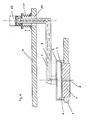
- Fig. 1 einen Querschnitt durch eine Vorrichtung nach der Erfindung,
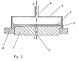
- Fig. 2 einen Querschnitt durch eine vergrösserte Einzelheit der Vorrichtung nach der Erfindung.
- In dem Ausführungsbeispiel nach Figur 1 ist die Rückplatte 1 in der Grundplatte 2 verankert. Diese Rückplatte weist eine von der Temperatur des plattenförmigen Objekts 5, beispielsweise einem Siliziumwafer, verschiedene Temperatur auf, kann also je nach Aufgabenstellung als Heiz- oder Kühlplatte ausgebildet sein. Auf dieser Rückplatte 1 liegt das Plättchen 5 auf, wobei bei einem Siliziumwafer auf Grund der Körnung der beiden Werkstoffe nur kleine Bereiche der beiden Oberflächen (typischerweise weniger als 5 %) tatsächlich miteinander in Kontakt stehen und dazwischen ein Zwischenraum gebildet wird, in den durch eine Bohrung 3 ein Gas eingeleitet werden kann. Dabei stellt sich bei entsprechendem Gasdruck in diesem Zwischenraum mindestens teilweise eine molekulare Strömung des Gases ein, das heisst, die freie Weglänge der Gaspartikel ist gross im Verhältnis zur Geometrie der Umgebung und die Gaspartikel stossen daher bevorzugt an den Oberflächen von Plättchen 5 und Rückplatte 1, nicht aber mit anderen Gaspartikel zusammen.
- Vorteilhafterweise wird das Plättchen 5 durch Zentrierstifte 4 in eine vorbestimmte Position gebracht.
- Ein Deckel 6 wird mechanisch auf die Grundplatte angepresst und schliesst Plättchen 5 und Rückplatte 1 gegen die Umgebung ab, welche typischerweise einen Gasdruck von 10⁻³ bis 10⁻⁴ mbar aufweist. Dabei wird es in vielen Fällen genügen, wenn ein sogenannter Diffusionsspalt zwischen Deckel 6 und Grundplatte 2 gebildet wird. Dieser Deckel 6 kann an einem Dreharm 7 in vertikaler Richtung und in horizontaler Richtung verschoben werden. Dieser Dreharm 7 ist seinerseits mit einer Durchführung 10 an einem zweiten Boden 9 verankert und mit einem integrierten Drehhubelement 11 und 12 verbunden. Durch Betätigen des Hubelementes 11 kann der Deckl in vertikaler Richtung verschoben und namentlich von der Grundplatte 2 abgehoben werden. Durch Drehung um die Längsachse des Drehelementes 12 kann er in horizontaler Richtung verschoben, namentlich über das fragliche Plättchen 5 gefahren werden.
- Drehachse 7 und Deckel 6 weisen entsprechende Bohrungen für das Einleiten eines Gases auf.
- Figur 2 zeigt die nähere Umgebung des Plättchens 5 und der Rückplatte 1 zwischen denen der Wärmeübergang stattfindet. Durch eine Dosiervorrichtung bekannter Bauart wird an den Stellen A und B gleichzeitig Gas eingeleitet und die Druckverhältnisse derart geregelt, dass der Druck zwischen Deckel 6 und Plättchen 5 ein Vielfaches des Druckes zwischen Rückplatte 1 und Plättchen 5 beträgt.Dazu müssen die Leitwerte der Gaszuleitungen zu der Plättchenvorderseite sowie in den Raum zwischen Plättchenrückseite und Rückplatte derart dimensioniert werden, dass die Plättchenvorderseite mit einem höheren Druck beaufschlagt wird, vorzugsweise 50 mbar Anpressdruck bei einem Druck des "Gaspolsters" von vorzugsweise 15 mbar. Dadurch wird das Plättchen 5 in optimaler Weise in Kontakt mit der Rückplatte 1 gebracht ohne, dass dabei eine mechanische Belastung des Plättchens 5 eintritt. Dabei ist zu berücksichtigen, dass die Oberfläche von standardmässigen, nichtpolierten Siliziumwaferrückseiten Krater von ca. 10 µm Durchmesser und ca. 5 µm Tiefe aufweisen, die auch mit grösseren Anpressdrücken nicht in direktem Kontakt mit der Rückplatte gebracht werden könnten.
- In einer verfahrensmässigen Veriante kann ein entsprechendes Druckverhältnis auch dadurch erzielt werden, dass das Gas nur bei A eingeleitet wird und über die Ränder des Plättchens 5 in den Zwischenraum zu der Rückplatte 1 eintritt und die Vorrichtung bei B verlässt.
- Wird die Rückplatte 1 als Heizplatte eingesetzt so kann es vorteilhaft sein, die Temperatur in deren Zentrum höher einzustellen als an deren Peripherie, so dass ein Temperaturgradient in der Heizplatte entsteht. Das kann beispielsweise dadurch bewirkt werden, dass die Heizdrähte verschieden dicht gewickelt werden oder dass zwei separat regelbare Heizdrahtsysteme in der Platte vorgesehen werden.
- Die Vorrichtung wird typischerweise in folgenden Verfahrensschritten eingesetzt: Das Plättchen 5 wird mit Hilfe der Zentrierstifte 4 auf der Rückplatte 1 placiert. Der Deckel 6 wird mechanisch auf der Grundplatte 2 angepresst und Gas durch die Bohrungen 3 und 8 ein- bzw. abgeleitet derart, dass sich das bereits erwähnte Druckverhältnis (vorzugweise 3:1 bis 10:1) einstellt. Das Plättchen 5 wird während einer vorbestimmten Zeit, beispielsweise einigen Sekunden, auf der Rückplatte 1 belassen, bis es die gewünschte Temperatur angenommen hat.
- Anschliessend wird der Deckel 6 wieder abgehoben und dadurch der Druckausgleich mit der Umgebung, typischerweise 10⁻³ bis 10⁻⁵ mbar erzielt. Schliesslich kann das Plättchen 5, welches nunmehr die gewünschte Temperatur aufweist, der weiteren Bearbeitung zugeführt werden.
- In einer typischen Versuchsanordnung wurden Siliziumwafer für die Produktion von Mikroprozessoren in einem Zeitintervall von 10 bis 15 Sekunden auf 500° C aufgeheizt. Der Druck zwischen Deckel und Plättchen betrug dabei 50 mbar, derjenige zwischen Plättchen und Rückplatte 15 mbar. Die Vorrichtung wurde in einer Anlage zur Kathodenzerstäubung mit einem Umgebungsdruck von 10⁻³ mbar betrieben und das verwendete Prozessgas war dabei Argon von handelsübliche Zusammensetzung.
Claims (10)
- eine Trägervorrichtung zur Aufnahme des plattenförmigen Objekts, welche eine von dem Objekt verschiedene Temperatur aufweist,
- eine Quelle eines unter Druck stehenden Gases,
- eine zwischen der Gasdruckquelle und dem Kontaktbereich zwischen Trägervorrichtung und plattenförmigem Objekt angeordnete Vorrichtung,durch welche Gas zwischen die Trägervorrichtung und das plattenförmige Objekt eingeführt bzw. daraus abgeleitet werden kann,
- ein relativ zu der Trägervorrichtung beweglicher Deckel,
- eine an der Trägervorrichtung dauerhaft befestigte Vorrichtung zur zeitweiligen Verankerung des Deckels,
- eine Vorrichtung zum Bewegen des Deckels und zu dessen zeitweiligem Anpressen an der Verankerung,
- eine zwischen der Gasdruckquelle und dem Hohlraum zwischen Trägervorrichtung und Deckel angeordnete Vorrichtung, durch welche Gas in diesen Hohlraum eingeleitet werden kann,
- eine Vorrichtung zwischen Gasquelle und den beiden Hohlräumen, welche es gestattet, die Gaszufuhr in den Hohlraum zwischen Deckel und plattenförmigem Objekt derart zu regeln, dass der Gasdruck in diesem Hohlraum denjenigen zwischen Trägervorrichtung und plattenförmigem Objekt übersteigt.
dadurch gekennzeichnet, dass die Trägervorrichtung eine ebene metallische Oberfläche aufweist.
dadurch gekennzeichnet, dass die Vorrichtung zur Einleitung von Gas durch den Deckel mindestens eine Bohrung durch den Deckel aufweist.
dadurch gekennzeichnet, dass sowohl durch den Deckel als auch durch die Trägervorrichtung Gas eingeleitet wird.
dadurchg gekennzeichnet, dass das Gas durch den Deckel eingeleitet und durch die Trägervorrichtung abgeleitet wird.
dadurch gekennzeichnet, dass die Trägervorrichtung als Heizplatte ausgebildet ist.
dadurch gekenbnzeichnet, dass die Trägervorrichtung als Kühlplatte ausgebildet ist.
- das plattenförmige Objekt auf die Trägervorrichtung placiert wird,
- dass ein Deckel über diesem Objekt mechanisch auf eine mit der Trägervorrichtung verbundene Verankerungsvorrichtung angepresst wird,
- dass ein Gas zwischen Deckel und Plättchen und zwischen Plättchen und Trägervorrichtung eingeleitet wird,
- dass der Gasdruck derart eingestellt wird, dass der Druck zwischen Deckel und Plättchen denjenigen zwischen Plättchen und Trägervorrichtung übersteigt,
- dass der Trägervorrichtung eine vorbestimmte Temperatur verliehen wird,
- dass das Plättchen während einer vorbestimmten Zeit in dieser Stellung belassen wird, bis es eine vorbestimmte Temperatur aufweist,
- dass der Deckel wieder von der Verankerungsvorrichtung entfernt wird und dadurch ein Druckausgleich mit der Umgebung erzielt wird, und
- dass das Plättchen einer weiteren Bearbeitung zugeführt wird.
dadurch gekennzeichnet, dass das Verhältnis zwischen dem Druck im Bereich zwischen Deckel und Plättchen und demjenigen im Bereich zwischen Plättchen und Trägervorrichtung zwischen 3 und 10 beträgt.
dadurch gekennzeichnet, dass der Druck zwischen Deckel und Plättchen 15 bis 5o mbar beträgt und das Plättchen 10 bis 20 Sekunden auf der Trägervorrichtung der Temperatureinwirkung ausgesetzt wird.
Priority Applications (1)
| Application Number | Priority Date | Filing Date | Title |
|---|---|---|---|
| AT88112869T ATE96576T1 (de) | 1987-12-03 | 1988-08-08 | Verfahren und vorrichtung zur uebertragung thermischer energie auf bzw. von einem plattenfoermigen substrat. |
Applications Claiming Priority (2)
| Application Number | Priority Date | Filing Date | Title |
|---|---|---|---|
| CH474787 | 1987-12-03 | ||
| CH4747/87 | 1987-12-03 |
Publications (3)
| Publication Number | Publication Date |
|---|---|
| EP0318641A2 true EP0318641A2 (de) | 1989-06-07 |
| EP0318641A3 EP0318641A3 (en) | 1990-08-29 |
| EP0318641B1 EP0318641B1 (de) | 1993-10-27 |
Family
ID=4281819
Family Applications (1)
| Application Number | Title | Priority Date | Filing Date |
|---|---|---|---|
| EP88112869A Expired - Lifetime EP0318641B1 (de) | 1987-12-03 | 1988-08-08 | Verfahren und Vorrichtung zur Übertragung thermischer Energie auf bzw. von einem plattenförmigen Substrat |
Country Status (5)
| Country | Link |
|---|---|
| US (1) | US4903754A (de) |
| EP (1) | EP0318641B1 (de) |
| JP (1) | JP2681672B2 (de) |
| AT (1) | ATE96576T1 (de) |
| DE (1) | DE3885240D1 (de) |
Cited By (1)
| Publication number | Priority date | Publication date | Assignee | Title |
|---|---|---|---|---|
| CN112917108A (zh) * | 2021-03-15 | 2021-06-08 | 宁波江丰电子材料股份有限公司 | 一种冷却盘体及其加工方法和用途 |
Families Citing this family (25)
| Publication number | Priority date | Publication date | Assignee | Title |
|---|---|---|---|---|
| ES2163388T3 (es) * | 1988-05-24 | 2002-02-01 | Unaxis Balzers Ag | Instalacion de vacio. |
| JP2504607B2 (ja) * | 1990-06-14 | 1996-06-05 | 株式会社東芝 | 半導体製造装置及び製造方法 |
| EP0491503A3 (de) * | 1990-12-19 | 1992-07-22 | AT&T Corp. | Verfahren zur Ablagerung von Metall |
| US5267607A (en) * | 1991-05-28 | 1993-12-07 | Tokyo Electron Limited | Substrate processing apparatus |
| US5424097A (en) * | 1993-09-30 | 1995-06-13 | Specialty Coating Systems, Inc. | Continuous vapor deposition apparatus |
| EP0733130A4 (de) * | 1993-12-17 | 1997-04-02 | Brooks Automation Inc | Vorrichtung zum heizen und kuehlen von wafers |
| US5471033A (en) * | 1994-04-15 | 1995-11-28 | International Business Machines Corporation | Process and apparatus for contamination-free processing of semiconductor parts |
| US5605600A (en) * | 1995-03-13 | 1997-02-25 | International Business Machines Corporation | Etch profile shaping through wafer temperature control |
| US5879808A (en) * | 1995-10-27 | 1999-03-09 | Alpha Metals, Inc. | Parylene polymer layers |
| US5709753A (en) * | 1995-10-27 | 1998-01-20 | Specialty Coating Sysetms, Inc. | Parylene deposition apparatus including a heated and cooled dimer crucible |
| JPH09326385A (ja) * | 1996-06-04 | 1997-12-16 | Tokyo Electron Ltd | 基板冷却方法 |
| US6001183A (en) * | 1996-06-10 | 1999-12-14 | Emcore Corporation | Wafer carriers for epitaxial growth processes |
| US6183565B1 (en) * | 1997-07-08 | 2001-02-06 | Asm International N.V | Method and apparatus for supporting a semiconductor wafer during processing |
| US5920797A (en) * | 1996-12-03 | 1999-07-06 | Applied Materials, Inc. | Method for gaseous substrate support |
| US5806319A (en) * | 1997-03-13 | 1998-09-15 | Wary; John | Method and apparatus for cryogenically cooling a deposition chamber |
| US6051276A (en) * | 1997-03-14 | 2000-04-18 | Alpha Metals, Inc. | Internally heated pyrolysis zone |
| US5841005A (en) * | 1997-03-14 | 1998-11-24 | Dolbier, Jr.; William R. | Parylene AF4 synthesis |
| US6054688A (en) * | 1997-06-25 | 2000-04-25 | Brooks Automation, Inc. | Hybrid heater with ceramic foil serrated plate and gas assist |
| US5911896A (en) * | 1997-06-25 | 1999-06-15 | Brooks Automation, Inc. | Substrate heating apparatus with glass-ceramic panels and thin film ribbon heater element |
| US6072163A (en) * | 1998-03-05 | 2000-06-06 | Fsi International Inc. | Combination bake/chill apparatus incorporating low thermal mass, thermally conductive bakeplate |
| US6529686B2 (en) | 2001-06-06 | 2003-03-04 | Fsi International, Inc. | Heating member for combination heating and chilling apparatus, and methods |
| US6547559B1 (en) | 2002-05-20 | 2003-04-15 | Veeco Instruments, Inc. | Clamping of a semiconductor substrate for gas-assisted heat transfer in a vacuum chamber |
| US6908512B2 (en) * | 2002-09-20 | 2005-06-21 | Blue29, Llc | Temperature-controlled substrate holder for processing in fluids |
| FR2897422B1 (fr) * | 2006-02-14 | 2008-05-16 | Messier Bugatti Sa | Dispositif d'etancheite pour une entree de gaz d'un four ou analogue |
| US8420981B2 (en) | 2009-11-13 | 2013-04-16 | Tel Nexx, Inc. | Apparatus for thermal processing with micro-environment |
Family Cites Families (5)
| Publication number | Priority date | Publication date | Assignee | Title |
|---|---|---|---|---|
| US4139051A (en) * | 1976-09-07 | 1979-02-13 | Rockwell International Corporation | Method and apparatus for thermally stabilizing workpieces |
| US4756815A (en) * | 1979-12-21 | 1988-07-12 | Varian Associates, Inc. | Wafer coating system |
| US4537244A (en) * | 1982-05-25 | 1985-08-27 | Varian Associates, Inc. | Method for optimum conductive heat transfer with a thin flexible workpiece |
| US4567938A (en) * | 1984-05-02 | 1986-02-04 | Varian Associates, Inc. | Method and apparatus for controlling thermal transfer in a cyclic vacuum processing system |
| JPH0236276Y2 (de) * | 1985-01-10 | 1990-10-03 |
-
1988
- 1988-08-08 DE DE88112869T patent/DE3885240D1/de not_active Expired - Lifetime
- 1988-08-08 AT AT88112869T patent/ATE96576T1/de active
- 1988-08-08 EP EP88112869A patent/EP0318641B1/de not_active Expired - Lifetime
- 1988-10-26 US US07/262,816 patent/US4903754A/en not_active Expired - Lifetime
- 1988-11-17 JP JP63289016A patent/JP2681672B2/ja not_active Expired - Lifetime
Cited By (2)
| Publication number | Priority date | Publication date | Assignee | Title |
|---|---|---|---|---|
| CN112917108A (zh) * | 2021-03-15 | 2021-06-08 | 宁波江丰电子材料股份有限公司 | 一种冷却盘体及其加工方法和用途 |
| CN112917108B (zh) * | 2021-03-15 | 2022-05-27 | 宁波江丰电子材料股份有限公司 | 一种冷却盘体及其加工方法和用途 |
Also Published As
| Publication number | Publication date |
|---|---|
| DE3885240D1 (de) | 1993-12-02 |
| EP0318641B1 (de) | 1993-10-27 |
| JP2681672B2 (ja) | 1997-11-26 |
| ATE96576T1 (de) | 1993-11-15 |
| EP0318641A3 (en) | 1990-08-29 |
| US4903754A (en) | 1990-02-27 |
| JPH01169293A (ja) | 1989-07-04 |
Similar Documents
| Publication | Publication Date | Title |
|---|---|---|
| EP0318641B1 (de) | Verfahren und Vorrichtung zur Übertragung thermischer Energie auf bzw. von einem plattenförmigen Substrat | |
| DE69636094T2 (de) | Elektrostatischer Halter | |
| DE3787993T2 (de) | Verfahren und Mittel zum gemeinsamen Sintern von Keramik/Metall-Mehrschichtsubstraten. | |
| DE60021848T2 (de) | Keramisches heizgerät | |
| EP0275433B1 (de) | Verfahren zur Befestigung von elektronischen Bauelementen auf einem Substrat, Folie zur Durchführung des Verfahrens und Verfahren zur Herstellung der Folie | |
| EP0242626B1 (de) | Verfahren zur Befestigung von elektronischen Bauelementen auf einem Substrat | |
| DE69635745T2 (de) | Elektrostatische Haltevorrichtung und Herstellungsverfahren derselben | |
| DE69217285T2 (de) | Keramische Leiterplatte | |
| WO2005013352A2 (de) | Verfahren zum herstellen eines halbleiterbauelements mit einem kunststoffgehäuse und trägerplatte zur durchführung des verfahrens | |
| DE19628237A1 (de) | Halbleitervorrichtung und Herstellungsverfahren der Gleichen | |
| DE69526286T2 (de) | Verfahren zur Herstellung eines keramischen Substrates | |
| EP3618993B1 (de) | Verfahren zum herstellen einer lötverbindung von bauteilen unter verwendung von haftmaterial für provisorische verbindung der bauteile | |
| DE102022113414A1 (de) | Verbundmaterial und Wärmeableitungsteil hieraus | |
| DE60316746T2 (de) | Keramischer Suszeptor | |
| DE60207282T2 (de) | Verkapselung des anschlusslots zur aufrechterhaltung der genauigkeit der anschlussposition | |
| DE69010561T2 (de) | Verfahren and Apparat zum Verbinden elektrischer Bauelemente mittels Lötelementen. | |
| DE112009000555T5 (de) | Isolationsträger und Verfahren zu dessen Herstellung | |
| DE3940933A1 (de) | Verfahren zur verformung von basisplatten | |
| DE10085266B4 (de) | Elektrostatischer Scheibenhalter | |
| EP3618994A1 (de) | Lötvorrichtung und verfahren zum herstellen einer lötverbindung unter verwendung von basis- und andruckplatten und einer anschlagvorrichtung | |
| DE69529366T2 (de) | Sinterteil für und Herstellung eines Substrates | |
| DE69316159T2 (de) | Verfahren zum Aufbringen von Kontakthöckern auf einer Halbleitervorrichtung sowie zum Verbinden dieser Vorrichtung mit einer Leiterplatte | |
| EP0105175A1 (de) | Vakuumgeformte elektrische Heizvorrichtung und Verfahren zu deren Herstellung | |
| EP0336335B1 (de) | Vorrichtung zum herstellen amorpher Keramikstoffe oder Metallegierungen | |
| DE10296931T5 (de) | Plasmabehandlungseinrichtung, Plasmabehandlungsverfahren, und Verfahren zur Herstellung eines Halbleiterbauelements |
Legal Events
| Date | Code | Title | Description |
|---|---|---|---|
| PUAI | Public reference made under article 153(3) epc to a published international application that has entered the european phase |
Free format text: ORIGINAL CODE: 0009012 |
|
| AK | Designated contracting states |
Kind code of ref document: A2 Designated state(s): AT BE CH DE ES FR GB IT LI NL SE |
|
| PUAL | Search report despatched |
Free format text: ORIGINAL CODE: 0009013 |
|
| AK | Designated contracting states |
Kind code of ref document: A3 Designated state(s): AT BE CH DE ES FR GB IT LI NL SE |
|
| 17P | Request for examination filed |
Effective date: 19900921 |
|
| 17Q | First examination report despatched |
Effective date: 19920714 |
|
| GRAA | (expected) grant |
Free format text: ORIGINAL CODE: 0009210 |
|
| AK | Designated contracting states |
Kind code of ref document: B1 Designated state(s): AT BE CH DE ES FR GB IT LI NL SE |
|
| PG25 | Lapsed in a contracting state [announced via postgrant information from national office to epo] |
Ref country code: IT Free format text: LAPSE BECAUSE OF FAILURE TO SUBMIT A TRANSLATION OF THE DESCRIPTION OR TO PAY THE FEE WITHIN THE PRE;WARNING: LAPSES OF ITALIAN PATENTS WITH EFFECTIVE DATE BEFORE 2007 MAY HAVE OCCURRED AT ANY TIME BEFORE 2007. THE CORRECT EFFECTIVE DATE MAY BE DIFFERENT FROM THE ONE RECORDED.SCRIBED TIME-LIMIT Effective date: 19931027 Ref country code: ES Free format text: THE PATENT HAS BEEN ANNULLED BY A DECISION OF A NATIONAL AUTHORITY Effective date: 19931027 Ref country code: BE Effective date: 19931027 Ref country code: SE Effective date: 19931027 |
|
| REF | Corresponds to: |
Ref document number: 96576 Country of ref document: AT Date of ref document: 19931115 Kind code of ref document: T |
|
| REF | Corresponds to: |
Ref document number: 3885240 Country of ref document: DE Date of ref document: 19931202 |
|
| GBT | Gb: translation of ep patent filed (gb section 77(6)(a)/1977) |
Effective date: 19931109 |
|
| ET | Fr: translation filed | ||
| PG25 | Lapsed in a contracting state [announced via postgrant information from national office to epo] |
Ref country code: AT Effective date: 19940808 |
|
| PLBE | No opposition filed within time limit |
Free format text: ORIGINAL CODE: 0009261 |
|
| STAA | Information on the status of an ep patent application or granted ep patent |
Free format text: STATUS: NO OPPOSITION FILED WITHIN TIME LIMIT |
|
| 26N | No opposition filed | ||
| REG | Reference to a national code |
Ref country code: GB Ref legal event code: IF02 |
|
| PGFP | Annual fee paid to national office [announced via postgrant information from national office to epo] |
Ref country code: CH Payment date: 20021030 Year of fee payment: 15 |
|
| PG25 | Lapsed in a contracting state [announced via postgrant information from national office to epo] |
Ref country code: CH Free format text: LAPSE BECAUSE OF NON-PAYMENT OF DUE FEES Effective date: 20030831 Ref country code: LI Free format text: LAPSE BECAUSE OF NON-PAYMENT OF DUE FEES Effective date: 20030831 |
|
| REG | Reference to a national code |
Ref country code: CH Ref legal event code: PL |
|
| PGFP | Annual fee paid to national office [announced via postgrant information from national office to epo] |
Ref country code: DE Payment date: 20070802 Year of fee payment: 20 |
|
| PGFP | Annual fee paid to national office [announced via postgrant information from national office to epo] |
Ref country code: GB Payment date: 20070809 Year of fee payment: 20 |
|
| PGFP | Annual fee paid to national office [announced via postgrant information from national office to epo] |
Ref country code: NL Payment date: 20070723 Year of fee payment: 20 |
|
| PGFP | Annual fee paid to national office [announced via postgrant information from national office to epo] |
Ref country code: FR Payment date: 20070808 Year of fee payment: 20 |
|
| REG | Reference to a national code |
Ref country code: GB Ref legal event code: PE20 Expiry date: 20080807 |
|
| NLV7 | Nl: ceased due to reaching the maximum lifetime of a patent |
Effective date: 20080808 |
|
| PG25 | Lapsed in a contracting state [announced via postgrant information from national office to epo] |
Ref country code: NL Free format text: LAPSE BECAUSE OF EXPIRATION OF PROTECTION Effective date: 20080808 |
|
| PG25 | Lapsed in a contracting state [announced via postgrant information from national office to epo] |
Ref country code: GB Free format text: LAPSE BECAUSE OF EXPIRATION OF PROTECTION Effective date: 20080807 |