EP0318436A1 - Gerät zum Nachprüfen von Werkstückabmessungen - Google Patents
Gerät zum Nachprüfen von Werkstückabmessungen Download PDFInfo
- Publication number
- EP0318436A1 EP0318436A1 EP88830467A EP88830467A EP0318436A1 EP 0318436 A1 EP0318436 A1 EP 0318436A1 EP 88830467 A EP88830467 A EP 88830467A EP 88830467 A EP88830467 A EP 88830467A EP 0318436 A1 EP0318436 A1 EP 0318436A1
- Authority
- EP
- European Patent Office
- Prior art keywords
- workpiece
- coupled
- support
- frame
- devices
- Prior art date
- Legal status (The legal status is an assumption and is not a legal conclusion. Google has not performed a legal analysis and makes no representation as to the accuracy of the status listed.)
- Pending
Links
Images



Classifications
-
- G—PHYSICS
- G01—MEASURING; TESTING
- G01B—MEASURING LENGTH, THICKNESS OR SIMILAR LINEAR DIMENSIONS; MEASURING ANGLES; MEASURING AREAS; MEASURING IRREGULARITIES OF SURFACES OR CONTOURS
- G01B5/00—Measuring arrangements characterised by the use of mechanical techniques
-
- G—PHYSICS
- G01—MEASURING; TESTING
- G01B—MEASURING LENGTH, THICKNESS OR SIMILAR LINEAR DIMENSIONS; MEASURING ANGLES; MEASURING AREAS; MEASURING IRREGULARITIES OF SURFACES OR CONTOURS
- G01B7/00—Measuring arrangements characterised by the use of electric or magnetic techniques
- G01B7/12—Measuring arrangements characterised by the use of electric or magnetic techniques for measuring diameters
-
- B—PERFORMING OPERATIONS; TRANSPORTING
- B23—MACHINE TOOLS; METAL-WORKING NOT OTHERWISE PROVIDED FOR
- B23Q—DETAILS, COMPONENTS, OR ACCESSORIES FOR MACHINE TOOLS, e.g. ARRANGEMENTS FOR COPYING OR CONTROLLING; MACHINE TOOLS IN GENERAL CHARACTERISED BY THE CONSTRUCTION OF PARTICULAR DETAILS OR COMPONENTS; COMBINATIONS OR ASSOCIATIONS OF METAL-WORKING MACHINES, NOT DIRECTED TO A PARTICULAR RESULT
- B23Q1/00—Members which are comprised in the general build-up of a form of machine, particularly relatively large fixed members
- B23Q1/01—Frames, beds, pillars or like members; Arrangement of ways
Definitions
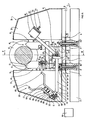
- the support and protection means include also a support structure 88 comprising two rotary arms 90 and 92 and support devices or supports 94 and 96 secured to bed 2, the rotary arms 90 and 92 being connected to supports 94 and 96, respectively.
- a support structure 88 comprising two rotary arms 90 and 92 and support devices or supports 94 and 96 secured to bed 2, the rotary arms 90 and 92 being connected to supports 94 and 96, respectively.
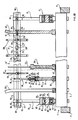
- the description hereinafter refers to arm 90 and associated support 94 only, as shown in figures 1 and 2.
- Rotary arm 90 comprises: a first elongated portion 132, a second elongated portion 134 - angularly coupled to the first - a third elongated portion 136 with a circular cross-section, an annular portion 138 - that connects said second and third elongated portions 134 and 136 in such a way that these portions 134, 136 are reciprocally sloping - the annular portion 138 comprising a hole 140 with an axis arranged transversally with respect to elongated portions 134, 136, and a counterweight end portion 142 connected to the third elongated portion 136.
- a first reference abutment element 146 is fixed to the second elongated portion 134 and is adapted for cooperating with reference abutment 128 for limiting the rotation of arm 90 in a clockwise direction (as shown in figure 1).
- a second reference abutment element 148 is coupled to portion 134, opposite to element 146, and a limit stop cap 150 is coupled to nut 112; element 148 and limit stop cap 150 cooperate for limiting the rotation of arm 90 in a direction opposite to the previously mentioned one.
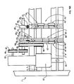
- the support structure 88 also comprises a frame 154, shown in figure 2, with two bars 156, 158 connected by segments 160, 162 coupled (welded) at their ends in such a way that bars 156, 158 are parallel and separated by a longitudinal opening 164 that forms a guide.
- Frame 154 is coupled to rotary arms 90, 92: more specifically it is fixed to the first elongated portions 132 by means of screws 166, that are inserted through holes 152 and opening 164 and then locked by nuts 168, according to the same method of clamping the various parts of the bench gauge to bed 2.
- Sensing or measuring means comprise gauges 170 of the "snap" type (only one of them is shown in figure 1) with an integral element 172 that has a coupling portion 174, two shaped end portions 176, 178 that carry feelers 180, 182 adapted for contacting the surface of workpiece 42, and two portions with a thinner section 184, 186 between the end portions and the coupling portion.
- the portions that have a thinner section 184, 186 allow end portions 176, 178 to accomplish limited rotational displacements with respect to the coupling portion 174.
- Resilient means 188 adapted for urging the end portions 176, 178 to a mutual approach
- limiting means 190 adapted for limiting the reciprocal displacements of end portions 176, 178
- transducer means 192 adapted for emitting electrical signals that depend on said mutual displacements, are coupled to both said end portions 176, 178.
- Control means comprise electric cables 278, not shown in figures 1 and 2 but in figure 7 only, which transmit signals from the transducer means 192 to connector blocks (not shown) and to processing and display units 194.
- the sensing or measuring means comprise second gauges 230 similar to gauge 170 which are fixed to a single limited zone of additional frame 210 according to the same coupling method used for coupling gauge 170 to frame 154.
- the transducer means 192 of gauge 170 can comprise a single transducer
- each gauge 230 for diameter checking normally comprises two transducers.
- further gauges for determining axial dimensions can be fixed to additional frame 210. Normally the gauges 170 carried by frame 154 are used for performing single relevant measurements, while gauges 230 carried by additional frame 210 are used for carrying out combined measurements (by processing the signals of gauges 230).
- gauges 170 The particular coupling of gauges 170 to frame 154 by means of just one bolt further prevents each of the sensing means 170 from being affected by possible plays due to inexact alignment of the axes of rotation of arms 90, 92, and/or bending of some parts of the apparatus.
- a similar advantage is ensured to the second sensing means 230 coupled to the additional frame 210 in turn coupled by just one bolt to frame 154: possible misalignments among a plurality of gauges 230 coupled to additional frame 210 due, for example, to clearances in the rotations of arms 90, 92 are prevented, allowing an improved accuracy and flexibility in checking axial distances, concentricity, parallelisms, etc.
- frame 210 can also be connected to frame 154 by means of two bolts positioned sufficiently close together, instead of one, in order to obtain the same result.
- Guide devices or bumpers 240, 242 are comprised in the support and protection means, and are coupled to bed 2 by means of bolts, in a quite similar way as for the other elements described up to now - for example like support 94 in the case of arm 90.
- the guide devices 240, 242 are adapted for limiting in an axial direction the positioning of workpiece 42 (that is not shown in figure 2 for simplicity's sake). Threaded through holes 244 in the guide devices (just the one referring to element 242 is shown in a sectional view in figure 2) can be used for the initial adjustment of rest devices 40.
- FIG. 7 schematically shows some details - that are not shown in the other figures - of the bench gauge described up to now, and in particular of further components of the support and protection means.
- a plate 260 with holes 272 is secured to and below frame 154, by means of two bridge elements 262, 264 and screws and bolts 266 and 268.
- Locking elements 270 made of plastic comprise a cylindrical end (not visible in the figure) adapted for insertion in a relevant hole 272 of plate 260, and a substantially annular portion 274 with a slit 276.
- the locking elements 270 are inserted in holes 272 in correspondence to the position of sensing means 170, 230 coupled to frame 154 (or to additional frame 210) In figure 7, for simplicity's sake, the sensing means are not explicitly shown, but just indicated by associated locking screws 198.
- Each cable 278 coming out of transducer means 192 of a guage 170 is inserted through slit 276, in the associated locking element 270 and in all the other elements 270 on plate 260 placed between the relevant gauge and arm 92.
- cables 278 so aligned along plate 260 are inserted in a raceway 280 fixed to arm 92 and extending up to pin 144, i.e. the axis of rotation of arm 92. In this way cables 278 can integrally rotate with the movable part of the support structure (90, 92, 154) without being subject to unwanted torsions.
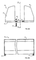
- Figure 9A schematically shows a bench for manual actuation wherein there are shown just bed 2′, support devices 94′, rotary arm 90 with actuation lever 320 and protection structure 20′.
- the asymmetric arrangement of bed 2′ and protection structure 20′ differs from that of the corresponding parts 2 and 20 in figure 1; this is due to the operator's need to reach one side of the bench for operating.
- Arm 90 is shown in figure 9A in a rest position, with the sensing means placed at the farthest distance from the workpiece; this distance is defined by the cooperation between the second reference abutment element 148 fixed to arm 90 and limit stop cap 150.
- limit stop element 344 contacts portion 136 of arm 90, forcing the whole arm to rotate in the same direction. From the moment in which contact element 336 contacts the surface of cam 338 the movement of lever 320 and that of arm 90 are dampened. Manually operated lever 320 continues its stroke until bent end 340 of flange 326 contacts a limit stop consisting in a surface portion of support devices 94′ (figure 9B).
- lever 320 In order to withdraw the gauges away from the workpiece, lever 320 is actuated so as to rotate in a counterclockwise direction (again reference should be made to figures 9A and 9B) and limit stop element 342 urges the entire arm 90 to rotate in the same direction, in order to return to the position shown in figure 9A.
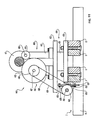
- a rest device 440 is shown in both figures 11 and 12, whereas a second rest device 410 is only shown in figure 12.
- Device 440 has a support member 444, with a coupling portion 468 fixed to bed 2, a central body 470 and a support part 472, all these parts being similar to corresponding parts of device 44.
- the second rest device 410 (visible in figure 12 only) comprises a second support member 412 that is substantially similar to member 444 and two second reference elements 414, 416, both substantially similar to element 448, arranged and adjusted in a symmetric way with respect to the axis of workpiece 42, so as to define - together with device 440 - the correct positioning of said workpiece 42.
- the adjustment means include two vertical support elements 420, 422 rigidly connected to section 468 of member 444 and to a corresponding part of member 412, each of them comprising a pair of longitudinal parallel flat bars 424, 426, respectively.
- Two bearings - not shown in the figures - are connected in a vertically adjustable way to said vertical support elements 420, 422, respectively, by means of adjustment means comprising junction elements 436, 438 locked by bolts 456 that pass through holes in elements 436, 438 and the opening formed between the pairs of flat bars 424, 426, and are suitably locked.
- a shaft 458 is supported by the bearings and so lies at one side of bed 2, parallel to bars 4, 6, 8 and 10, free to rotate about its axis.
- the position of the fourth pulley 482, or that of motor 476, is also set (in a way not shown in the drawing) by effecting transversal adjustments, in order to keep the tension of the second belt 484 substantially constant.
- FIG. 1 Another embodiment - not shown in the figures - of the apparatus according to the invention, provides for a structure quite similar to that shown in figures 1 and 2, with fixed rest devices 40, and enables to check the workpiece 42 during its rotation.
- the support and protection means comprise additional support members with two oppositely arranged centres, which are sustained by elements fixed to bed 2 in the way repeatedly described hereinbefore (for example like devices 40 in figures 1 and 2) and are longitudinally adjustable along guides 16, 18. These centres are aligned to define as axis and can rotate about said axis; the control means comprise an electric motor coupled to one of said centres, whereas the other centre (“dead centre”) is free to rotate "idle”.
- the loading of a workpiece 42 to be checked in said apparatus occurs first on the reference devices 40; then the dead centre is brought to contact an end of the workpiece 42 and urges the other end of said workpiece against the other centre in such a way that the axis defined by the centres and the geometrical axis of the workpiece 42 coincide and the workpiece 42 is slightly raised and remains supported by the centres only; then the motor is actuated so as to provide the workpiece rotation.
- the workpiece 42 can be pushed by the dead centre towards the other centre without having to approach the stationary workpiece from both sides. This possibility is provided as there are no sensing means coupled to the workpiece rest devices during the workpiece loading phase, and consequently during said phase the sensing means are not subjected to possible slidings and/or damages.
Landscapes
- Physics & Mathematics (AREA)
- General Physics & Mathematics (AREA)
- Engineering & Computer Science (AREA)
- Mechanical Engineering (AREA)
- A Measuring Device Byusing Mechanical Method (AREA)
- Jigs For Machine Tools (AREA)
Applications Claiming Priority (2)
| Application Number | Priority Date | Filing Date | Title |
|---|---|---|---|
| IT8703683A IT1213718B (it) | 1987-11-09 | 1987-11-09 | Apparecchio per il controllo di caratteristiche di pezzi a simmetria di rotazioni |
| IT368387 | 1987-11-09 |
Publications (1)
| Publication Number | Publication Date |
|---|---|
| EP0318436A1 true EP0318436A1 (de) | 1989-05-31 |
Family
ID=11111367
Family Applications (4)
| Application Number | Title | Priority Date | Filing Date |
|---|---|---|---|
| EP88830467A Pending EP0318436A1 (de) | 1987-11-09 | 1988-11-03 | Gerät zum Nachprüfen von Werkstückabmessungen |
| EP88909605A Expired - Lifetime EP0340271B1 (de) | 1987-11-09 | 1988-11-03 | Gerät zum nachprüfen von werkstückabmessungen |
| EP88830468A Pending EP0318437A1 (de) | 1987-11-09 | 1988-11-03 | Gerät zum Nachprüfen von Werkstückabmessungen |
| EP88909606A Expired - Lifetime EP0340272B1 (de) | 1987-11-09 | 1988-11-03 | Gerät zum nachprüfen von werkstückabmessungen |
Family Applications After (3)
| Application Number | Title | Priority Date | Filing Date |
|---|---|---|---|
| EP88909605A Expired - Lifetime EP0340271B1 (de) | 1987-11-09 | 1988-11-03 | Gerät zum nachprüfen von werkstückabmessungen |
| EP88830468A Pending EP0318437A1 (de) | 1987-11-09 | 1988-11-03 | Gerät zum Nachprüfen von Werkstückabmessungen |
| EP88909606A Expired - Lifetime EP0340272B1 (de) | 1987-11-09 | 1988-11-03 | Gerät zum nachprüfen von werkstückabmessungen |
Country Status (9)
| Country | Link |
|---|---|
| US (2) | US5086569A (de) |
| EP (4) | EP0318436A1 (de) |
| JP (2) | JP2682861B2 (de) |
| KR (2) | KR0122130B1 (de) |
| BR (2) | BR8807286A (de) |
| DE (2) | DE3878225T2 (de) |
| ES (2) | ES2038791T3 (de) |
| IT (1) | IT1213718B (de) |
| WO (2) | WO1989004455A1 (de) |
Families Citing this family (29)
| Publication number | Priority date | Publication date | Assignee | Title |
|---|---|---|---|---|
| IT1213718B (it) * | 1987-11-09 | 1989-12-29 | Marposs Spa | Apparecchio per il controllo di caratteristiche di pezzi a simmetria di rotazioni |
| IT1242648B (it) * | 1990-05-30 | 1994-05-16 | Marposs Spa | Metodo per il controllo dimensionale dinamico di pezzi meccanici, e relativo apparecchio. |
| IT1266221B1 (it) * | 1993-01-21 | 1996-12-27 | Marposs Spa | Apparecchiatura per il controllo geometrico di pezzi a simmetria di rotazione |
| US5460058A (en) * | 1994-03-02 | 1995-10-24 | Trw Vehicle Safety Systems Inc. | Apparatus and method for inspecting an air bag module |
| DE4420137A1 (de) * | 1994-06-09 | 1995-12-14 | Zeiss Messgeraetebau Gmbh | Meßgerät zur Überprüfung der Abmessungen von zylindrischen Werkstücken |
| IT1279641B1 (it) | 1995-10-03 | 1997-12-16 | Marposs Spa | Apparecchio per il controllo del diametro di perni di biella in moto orbitale |
| DE69608291T2 (de) * | 1995-10-06 | 2001-01-04 | Etamic S.A., Saint-Martin-Des-Entrees | Mess-und regelgerät für die bearbeitung von umlaufenden zylindrischen werkstücken |
| US6463669B1 (en) * | 1998-04-15 | 2002-10-15 | Rollomatic S.A. | Apparatus for checking the shape of a part |
| US6298572B1 (en) | 2000-01-10 | 2001-10-09 | Mcauley Brian | Universal holding device for effectuating three dimensional measurement of a part and method of constructing such a holding device |
| ITBO20000012A1 (it) * | 2000-01-18 | 2001-07-18 | Marposs Spa | Apparecchiatura per il controllo del diametro di perni . |
| DE20003772U1 (de) * | 2000-03-01 | 2001-07-19 | Prüftechnik Dieter Busch AG, 85737 Ismaning | Adapter zum Überprüfen der winkelmassigen Ausrichtung einer präzise zu lagernden Walze |
| JP2002168616A (ja) * | 2000-11-30 | 2002-06-14 | Fuji Photo Film Co Ltd | ロール状物の周面形状測定装置 |
| SE0401408D0 (sv) * | 2004-06-02 | 2004-06-02 | Astrazeneca Ab | Diameter measuring device |
| JP4923549B2 (ja) * | 2005-12-08 | 2012-04-25 | 株式会社ジェイテクト | 定寸装置の取付構造 |
| CN101598538A (zh) * | 2008-06-04 | 2009-12-09 | 鸿富锦精密工业(深圳)有限公司 | 工件检测装置 |
| US7748134B1 (en) * | 2009-03-09 | 2010-07-06 | Yao-Chung Wang | Measuring device for cylinder |
| DE102009032353A1 (de) | 2009-07-08 | 2011-09-08 | Hommel-Etamic Gmbh | Verfahren zur Ermittlung der Form eines Werkstücks |
| DE102009042252B4 (de) | 2009-09-22 | 2014-03-06 | Jenoptik Industrial Metrology Germany Gmbh | Meßvorrichtung |
| DE102010013069B4 (de) * | 2010-03-26 | 2012-12-06 | Hommel-Etamic Gmbh | Meßvorrichtung |
| DE102010035147B4 (de) | 2010-08-23 | 2016-07-28 | Jenoptik Industrial Metrology Germany Gmbh | Meßvorrichtung |
| DE102012018580B4 (de) | 2012-09-20 | 2015-06-11 | Jenoptik Industrial Metrology Germany Gmbh | Messvorrichtung und Messverfahren zur Inprozess-Messung an Prüflingen während eines Bearbeitungsvorganges an einer Bearbeitungsmaschine, insbesondere einer Schleifmaschine |
| US9897428B2 (en) * | 2014-12-22 | 2018-02-20 | Monte Hieb | Diametral measurement system for evaluation of cylindrical objects, including rock cores |
| CN104964127A (zh) * | 2015-05-14 | 2015-10-07 | 广西金达造船有限公司 | 一种主机座结构 |
| IT201700088988A1 (it) * | 2017-08-02 | 2019-02-02 | Marposs Spa | Apparecchiatura per il controllo di dimensioni diametrali di un perno in moto orbitale |
| EP3743677B1 (de) * | 2018-01-22 | 2021-04-28 | Reginald Galestien | Verfahren und vorrichtung zur messung der durchmesser von zylindrischen messstiften |
| KR102352966B1 (ko) * | 2019-12-02 | 2022-01-20 | 주식회사 호원 | 단차 측정 장치 |
| CN110925528A (zh) * | 2019-12-12 | 2020-03-27 | 徐州市工业设备安装有限责任公司 | 一种用于机电设备安装的调节装置 |
| CN112664759A (zh) * | 2021-01-15 | 2021-04-16 | 李奇 | 一种农业机械田间作业智能管理器 |
| DE102022123873B3 (de) | 2022-09-17 | 2024-03-07 | Schübel GmbH | Prüf- oder Messvorrichtung |
Citations (5)
| Publication number | Priority date | Publication date | Assignee | Title |
|---|---|---|---|---|
| DE837608C (de) * | 1949-10-18 | 1952-04-28 | Rudolf Westenberger | Vorrichtung zum UEberwachen und Messen des Schleifvorganges an Rundschleifmaschinen |
| US2625773A (en) * | 1949-10-20 | 1953-01-20 | Fortuna Werke Spezialmaschinen | Automatic circular grinding machine |
| US2688802A (en) * | 1949-03-01 | 1954-09-14 | Perfect Circle Corp | Machine mounted diameter gauge |
| FR1507371A (fr) * | 1966-11-18 | 1967-12-29 | Bonnet Ets | Perfectionnements à la constitution d'appareils de vérification simultanée de plusieurs dimensions d'objets nombreux |
| US3905116A (en) * | 1973-10-15 | 1975-09-16 | Allis Chalmers | Crankshaft bearing measuring apparatus |
Family Cites Families (19)
| Publication number | Priority date | Publication date | Assignee | Title |
|---|---|---|---|---|
| US1587217A (en) * | 1924-11-12 | 1926-06-01 | Wymangordon Company | Crank-shaft indexing machine |
| US2609609A (en) * | 1946-07-10 | 1952-09-09 | Western Electric Co | Gauge for checking parts of cylindrical articles |
| US2854756A (en) * | 1950-11-04 | 1958-10-07 | Sheffield Corp | Gauging device for checking size or contour |
| US3011780A (en) * | 1958-01-02 | 1961-12-05 | Hanisko Joseph | Universal gauge |
| NL292039A (de) * | 1962-04-27 | |||
| US3281995A (en) * | 1963-12-20 | 1966-11-01 | Farrel Corp | Machine tool |
| GB1093183A (en) * | 1964-05-28 | 1967-11-29 | Rank Precision Ind Ltd | Improvements in or relating to apparatus for testing the diameter of a cylindrical surface |
| US3302920A (en) * | 1964-09-25 | 1967-02-07 | Caterpillar Tractor Co | Apparatus for producing templates |
| GB1335949A (en) * | 1971-05-28 | 1973-10-31 | Fiat Spa | Apparatus for dimensional testing of nominally cylindrical workpieces |
| US4006529A (en) * | 1975-09-08 | 1977-02-08 | Herman Martin A | Check gage for article thickness |
| US4122608A (en) * | 1977-04-22 | 1978-10-31 | Teledyne Industries, Inc. | Tube feeler |
| US4233744A (en) * | 1978-12-01 | 1980-11-18 | Finike Italiana Marposs S.P.A. | Apparatus for the geometrical checking of workpieces having surfaces of rotation |
| AT385121B (de) * | 1982-10-15 | 1988-02-25 | Steyr Daimler Puch Ag | Vorrichtung zum messen bzw. ueberwachen der durchmesser stabfoermiger werkstuecke |
| IT1169180B (it) * | 1983-03-09 | 1987-05-27 | Finike Italiana Marposs | Comparatore per il controllo di dimensioni lineari di pezzi meccanici |
| IT1180539B (it) * | 1984-10-15 | 1987-09-23 | Finike Italiana Marposs | Testa per il controllo di dimensioni pezzi meccanici |
| US4604810A (en) * | 1985-08-29 | 1986-08-12 | The Monarch Machine Tool Company | Post process diameter gage |
| IT1191688B (it) * | 1986-03-20 | 1988-03-23 | Giustina International Spa | Macchina rettificatrice per cilindri con organi di rilievo e controllo dimensionale e superficiale |
| IT1213718B (it) * | 1987-11-09 | 1989-12-29 | Marposs Spa | Apparecchio per il controllo di caratteristiche di pezzi a simmetria di rotazioni |
| US4914827A (en) * | 1988-12-28 | 1990-04-10 | Gte Valenite Corporation | Protection technique for gage heads |
-
1987
- 1987-11-09 IT IT8703683A patent/IT1213718B/it active
-
1988
- 1988-11-03 ES ES198888909605T patent/ES2038791T3/es not_active Expired - Lifetime
- 1988-11-03 JP JP63508870A patent/JP2682861B2/ja not_active Expired - Lifetime
- 1988-11-03 ES ES198888909606T patent/ES2031640T3/es not_active Expired - Lifetime
- 1988-11-03 DE DE8888909605T patent/DE3878225T2/de not_active Expired - Fee Related
- 1988-11-03 EP EP88830467A patent/EP0318436A1/de active Pending
- 1988-11-03 KR KR1019890701297A patent/KR0122130B1/ko not_active Expired - Fee Related
- 1988-11-03 BR BR888807286A patent/BR8807286A/pt not_active IP Right Cessation
- 1988-11-03 WO PCT/IT1988/000077 patent/WO1989004455A1/en not_active Ceased
- 1988-11-03 EP EP88909605A patent/EP0340271B1/de not_active Expired - Lifetime
- 1988-11-03 JP JP63508871A patent/JP2682862B2/ja not_active Expired - Lifetime
- 1988-11-03 WO PCT/IT1988/000078 patent/WO1989004456A1/en not_active Ceased
- 1988-11-03 EP EP88830468A patent/EP0318437A1/de active Pending
- 1988-11-03 BR BR888807301A patent/BR8807301A/pt not_active IP Right Cessation
- 1988-11-03 EP EP88909606A patent/EP0340272B1/de not_active Expired - Lifetime
- 1988-11-03 DE DE8888909606T patent/DE3871380D1/de not_active Expired - Lifetime
- 1988-11-03 US US07/381,647 patent/US5086569A/en not_active Expired - Fee Related
- 1988-11-03 KR KR1019890701298A patent/KR0122129B1/ko not_active Expired - Fee Related
-
1989
- 1989-06-16 US US07/378,194 patent/US5068974A/en not_active Expired - Fee Related
Patent Citations (5)
| Publication number | Priority date | Publication date | Assignee | Title |
|---|---|---|---|---|
| US2688802A (en) * | 1949-03-01 | 1954-09-14 | Perfect Circle Corp | Machine mounted diameter gauge |
| DE837608C (de) * | 1949-10-18 | 1952-04-28 | Rudolf Westenberger | Vorrichtung zum UEberwachen und Messen des Schleifvorganges an Rundschleifmaschinen |
| US2625773A (en) * | 1949-10-20 | 1953-01-20 | Fortuna Werke Spezialmaschinen | Automatic circular grinding machine |
| FR1507371A (fr) * | 1966-11-18 | 1967-12-29 | Bonnet Ets | Perfectionnements à la constitution d'appareils de vérification simultanée de plusieurs dimensions d'objets nombreux |
| US3905116A (en) * | 1973-10-15 | 1975-09-16 | Allis Chalmers | Crankshaft bearing measuring apparatus |
Also Published As
| Publication number | Publication date |
|---|---|
| IT1213718B (it) | 1989-12-29 |
| BR8807286A (pt) | 1990-03-27 |
| KR890701985A (ko) | 1989-12-22 |
| JPH02502124A (ja) | 1990-07-12 |
| ES2031640T3 (es) | 1992-12-16 |
| KR890701984A (ko) | 1989-12-22 |
| ES2038791T3 (es) | 1993-08-01 |
| DE3878225D1 (de) | 1993-03-18 |
| KR0122130B1 (ko) | 1997-11-11 |
| JP2682862B2 (ja) | 1997-11-26 |
| JP2682861B2 (ja) | 1997-11-26 |
| JPH02502125A (ja) | 1990-07-12 |
| EP0340271A1 (de) | 1989-11-08 |
| EP0340271B1 (de) | 1993-02-03 |
| WO1989004455A1 (en) | 1989-05-18 |
| EP0340272A1 (de) | 1989-11-08 |
| IT8703683A0 (it) | 1987-11-09 |
| BR8807301A (pt) | 1990-04-17 |
| EP0340272B1 (de) | 1992-05-20 |
| US5068974A (en) | 1991-12-03 |
| WO1989004456A1 (en) | 1989-05-18 |
| KR0122129B1 (ko) | 1997-11-11 |
| US5086569A (en) | 1992-02-11 |
| EP0318437A1 (de) | 1989-05-31 |
| DE3871380D1 (de) | 1992-06-25 |
| DE3878225T2 (de) | 1993-05-27 |
Similar Documents
| Publication | Publication Date | Title |
|---|---|---|
| US5086569A (en) | Apparatus for checking dimensions of workpieces | |
| US5129152A (en) | Fast contact measuring machine | |
| EP0806627B1 (de) | Anordnung zum Kontrollieren der Dimensionen eines mechanischen Stucks und Verfahren zum Betrieb der Anordnung | |
| GB2229990A (en) | Gripping device for handling components | |
| CN110231009B (zh) | 一种车轮螺栓孔位置度自动检测装置及方法 | |
| EP0181460B1 (de) | Messkopf zur Dimensionsüberwachung von mechanischen Teilen | |
| KR20150004756A (ko) | 본드 검사기 및 복수의 검사 공구들을 포함하는 본드 검사기용 카트리지 | |
| JP2648647B2 (ja) | 圧入体圧入方法及び圧入体の測長器付き圧入装置 | |
| GB2112522A (en) | Coordinate measuring machine | |
| US3135106A (en) | Static-dynamic fatigue-creep testing apparatus | |
| EP1802937B1 (de) | Vorrichtung zur abmessungs- und/oder geometrischen prüfung mechanischer teile | |
| EP3743677B1 (de) | Verfahren und vorrichtung zur messung der durchmesser von zylindrischen messstiften | |
| US20090076757A1 (en) | Methods of calibrating a measuring device | |
| CN223500292U (zh) | 一种弹性轴加工用检测装置 | |
| CN120721034B (zh) | 一种用于轮毂单元车削平面高度检测装置及其检测方法 | |
| CN110608693B (zh) | 应急驱动杆检测设备 | |
| CN223389157U (zh) | 一种轴用的综合检具 | |
| CN222069598U (zh) | 多角度高精轮廓度检测装置 | |
| CN111982486B (zh) | 一种弹簧自动检测装置 | |
| KR0184951B1 (ko) | 바소재의 휨량 측정장치 | |
| CN110319756B (zh) | 一种汽车座椅侧板焊接平面度检测用具及检测方法 | |
| KR19980058872A (ko) | 축 가공물의 길이 및 센터 측정장치 |
Legal Events
| Date | Code | Title | Description |
|---|---|---|---|
| PUAI | Public reference made under article 153(3) epc to a published international application that has entered the european phase |
Free format text: ORIGINAL CODE: 0009012 |
|
| AK | Designated contracting states |
Kind code of ref document: A1 Designated state(s): ES |
|
| STAA | Information on the status of an ep patent application or granted ep patent |
Free format text: STATUS: REQUEST FOR EXAMINATION WAS MADE |
|
| 17P | Request for examination filed |
Effective date: 19891113 |
|
| XX | Miscellaneous (additional remarks) |
Free format text: VERFAHREN ABGESCHLOSSEN INFOLGE VERBINDUNG MIT 88909606.1/0340272 (EUROPAEISCHE ANMELDENUMMER/VEROEFFENTLICHUNGSNUMMER) VOM 23.05.90. |