EP0318354B1 - Kraftfahrzeuginformationsübertragungsvorrichtung und Verfahren zur Anwendung der Vorrichtung - Google Patents
Kraftfahrzeuginformationsübertragungsvorrichtung und Verfahren zur Anwendung der Vorrichtung Download PDFInfo
- Publication number
- EP0318354B1 EP0318354B1 EP88402863A EP88402863A EP0318354B1 EP 0318354 B1 EP0318354 B1 EP 0318354B1 EP 88402863 A EP88402863 A EP 88402863A EP 88402863 A EP88402863 A EP 88402863A EP 0318354 B1 EP0318354 B1 EP 0318354B1
- Authority
- EP
- European Patent Office
- Prior art keywords
- transmitting
- information
- lines
- derivative
- establishing
- Prior art date
- Legal status (The legal status is an assumption and is not a legal conclusion. Google has not performed a legal analysis and makes no representation as to the accuracy of the status listed.)
- Expired - Lifetime
Links
- 230000005540 biological transmission Effects 0.000 title claims description 38
- 239000003990 capacitor Substances 0.000 claims description 6
- 238000007493 shaping process Methods 0.000 claims description 5
- 210000000056 organ Anatomy 0.000 description 11
- 238000010586 diagram Methods 0.000 description 6
- 244000045947 parasite Species 0.000 description 3
- 230000010287 polarization Effects 0.000 description 2
- 230000000295 complement effect Effects 0.000 description 1
- 238000012790 confirmation Methods 0.000 description 1
- 230000001276 controlling effect Effects 0.000 description 1
- 230000000694 effects Effects 0.000 description 1
- 230000036039 immunity Effects 0.000 description 1
- 230000003647 oxidation Effects 0.000 description 1
- 238000007254 oxidation reaction Methods 0.000 description 1
- 230000001105 regulatory effect Effects 0.000 description 1
- 239000004065 semiconductor Substances 0.000 description 1
Images
Classifications
-
- H—ELECTRICITY
- H04—ELECTRIC COMMUNICATION TECHNIQUE
- H04L—TRANSMISSION OF DIGITAL INFORMATION, e.g. TELEGRAPHIC COMMUNICATION
- H04L5/00—Arrangements affording multiple use of the transmission path
- H04L5/14—Two-way operation using the same type of signal, i.e. duplex
-
- B—PERFORMING OPERATIONS; TRANSPORTING
- B60—VEHICLES IN GENERAL
- B60R—VEHICLES, VEHICLE FITTINGS, OR VEHICLE PARTS, NOT OTHERWISE PROVIDED FOR
- B60R16/00—Electric or fluid circuits specially adapted for vehicles and not otherwise provided for; Arrangement of elements of electric or fluid circuits specially adapted for vehicles and not otherwise provided for
- B60R16/02—Electric or fluid circuits specially adapted for vehicles and not otherwise provided for; Arrangement of elements of electric or fluid circuits specially adapted for vehicles and not otherwise provided for electric constitutive elements
- B60R16/03—Electric or fluid circuits specially adapted for vehicles and not otherwise provided for; Arrangement of elements of electric or fluid circuits specially adapted for vehicles and not otherwise provided for electric constitutive elements for supply of electrical power to vehicle subsystems or for
- B60R16/0315—Electric or fluid circuits specially adapted for vehicles and not otherwise provided for; Arrangement of elements of electric or fluid circuits specially adapted for vehicles and not otherwise provided for electric constitutive elements for supply of electrical power to vehicle subsystems or for using multiplexing techniques
Definitions
- the present invention relates to a device for transmitting information between at least two components of a motor vehicle and a use of this device.
- the invention relates to differential information transmission devices, which have been developed during the definition of transmission systems for motor vehicles, because of a number of problems related to these applications, and in particular parasites that can disrupt these transmissions.
- the object of the invention is therefore to solve these problems by proposing an information transmission device which is reliable, simple, of a low cost price and which makes it possible to ensure sufficient information transmission even when the one of the transmission lines is disturbed.
- the subject of the invention is a device for transmitting differential information between at least two components of a motor vehicle, each of which comprises means for transmitting and means for receiving information, connected by two information transmission lines, characterized in that it comprises means for processing the signals circulating in the information transmission lines so as to allow operation of the device in degraded mode from the signals circulating on one information transmission lines, the processing means comprising means for establishing the derivative of the signals passing over the information transmission lines and means for shaping the output signals of said means for establishing the derivative, provided in the reception means of each member, and in that the reception means comprise means generating a bias voltage connected to the means for establishing the derivative.
- the invention also relates to the use of a device as described above, in which one of the organs is a master organ and the other is a slave organ, the master organ emitting a word of synchronization before each message, and the slave member transmitting a response message, characterized in that, before transmitting its response message, the slave member also transmits a synchronization word.
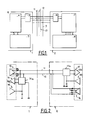
- a device for transmitting differential information comprises at least two members 1 and 2 arranged for example at different locations of a motor vehicle, for controlling different elements of the vehicle. and one of which, for example 1, is a master member and the other 2, a slave member.
- the device according to the invention can also be applied to a multi-master system.
- Each member 1 or 2 includes means for example 3, for member 1, of transmitting and receiving information connected to means 4 for managing the information exchange protocol of the member, these means 4 being themselves connected to interface means 5 for example with a microprocessor, an analog-digital converter or input-output ports.
- the member 2 comprises equivalent members respectively referenced by 6,7 and 8. Each member receives via supply lines 9 and 10, a supply for example + 12V - 0V.
- two lines for transmitting information 11 and 12 are also connected to the means for transmitting and receiving information 3 and 6 from members 1 and 2 respectively, these lines also being connected for example to other members arranged other places in the motor vehicle.
- each body for example 1 has, connected to the lines 11 and 12, means 13 for transmitting information, means 14 for receiving information as well as means 15 for generating a bias voltage connected to the means for receiving information 14.
- the member 2 comprises equivalent means referenced respectively by 16.17 and 18.
- the information reception means 14 and 17 comprise on the one hand means 14a and 17a for establishing the derivative of the signals passing through the transmission lines 11 and 12 and on the other hand means 14b and 17b for setting in the form of output signals from these means.
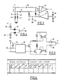
- Fig.3 shows in more detail an embodiment of the receiving means 14 or 17 described with reference to Fig.2, we see that the lines 11 and 12 are connected to the inputs d a comparator 19 through capacitors 20 and 21.
- the comparator 19 is constituted by a comparator with reliable offset and hysteresis centered, with respect to the bias voltage, produced for example using a comparator LM 139 manufactured by the National Semiconductors Company.
- Lines 11 and 12 are also connected to ground through capacitors 24.25 in series with resistors 26.27 respectively.
- the capacitors 24 and 25 and the resistors 26 and 27 constitute means for regulating the passband of each line.
- the polarization means for their part comprise a resistance bridge 28 and 29 connected to the input of an amplifier 30, the output of which is connected on the one hand to ground through a capacitor 31 and on the other hand to the line. 11 through a resistor 32 and at line 12 through a resistor 34.
- the capacitors 20 and 21 as well as the resistors 32 and 34 connected in bridge to the input terminals of the comparator 19, constitute the means for establishing the derivative of the signals passing through the information transmission lines 11 and 12, while the comparator 19 constitutes the means for shaping the output signals of these means before their transmission to the rest of the means for processing the organs. This allows the organs to work on the fronts of the signals and no longer on the slots of these and allows the device to operate even when one of the lines 11 or 12 is disturbed.
- the comparator 19 receives the derivatives of the signals passing through these lines and operates normally in differential.
- the comparator receives the derivative of the signals passing through in the other line, which is enough for it to operate, due to the polarization.
- the transmission of information can be done in a normal differential mode by a transmission on two lines or in degraded mode on one line, by determining the derivative of the signals in this line, and by reshaping the output signals of the means establishment of the derivative, the comparator 19 inputs being biased by the amplifier 30.
- FIG. 4 where a block diagram of the information transmission means forming part of a device according to the invention has been shown, it can be seen that these comprise a first current generator 36, one terminal of which is connected to the positive terminal of a power supply and the output of which is connected through two diodes 37 and 38 connected in series, to the input of a second current generator 39 of which the output is connected to ground.
- the transmission line for example 11, is connected to the midpoint between the two diodes 37,38.
- the diodes 37 and 38 make it possible, in reception mode of the corresponding member, to prevent the transistors of the current generators 36, 39 from turning on when the voltages of the parasites exceed the supply voltages of the circuit. .
- These information transmission means are shown in more detail in FIG. 5 where there are the diodes 37 and 38 as well as the information transmission line 11.
- the data inputs in E1 are directed to control means 40 of known type, the outputs of which are connected to current generating means, for example with transistors mounted in current mirrors of known type per se.
- the inputs E1 are also directed at E2 to an equivalent circuit for the supply line 12, after inversion in a gate 41, so as to obtain the signal complementary to the signal passing over the line 11, on the line 12.
- Fig. 6 Uses (Fig. 6) of differential information transmission devices, in which one of the organs is a master organ and the other is a slave organ, comprise a certain number of steps which include transmission from from the master unit 1 with a synchronization word, then an address word, enabling the corresponding slave unit 2 to be activated, a data word for the addressed unit and finally a control word .
- the addressed unit After a moment corresponding to the device turnaround time, the addressed unit transmits to the master unit, for example, an address word, a data word and finally a control word, as confirmation.
- the slave member before transmitting its response, the slave member also transmits a synchronization word allowing good time registration of the message during its transmission to other members.
Landscapes
- Engineering & Computer Science (AREA)
- Signal Processing (AREA)
- Computer Networks & Wireless Communication (AREA)
- Dc Digital Transmission (AREA)
- Arrangements For Transmission Of Measured Signals (AREA)
- Selective Calling Equipment (AREA)
- Small-Scale Networks (AREA)
Claims (6)
Applications Claiming Priority (2)
| Application Number | Priority Date | Filing Date | Title |
|---|---|---|---|
| FR8716367 | 1987-11-25 | ||
| FR8716367A FR2623674B1 (fr) | 1987-11-25 | 1987-11-25 | Dispositif de transmission d'informations pour vehicule automobile et procede de mise en oeuvre d'un tel dispositif |
Publications (2)
| Publication Number | Publication Date |
|---|---|
| EP0318354A1 EP0318354A1 (de) | 1989-05-31 |
| EP0318354B1 true EP0318354B1 (de) | 1992-07-01 |
Family
ID=9357165
Family Applications (1)
| Application Number | Title | Priority Date | Filing Date |
|---|---|---|---|
| EP88402863A Expired - Lifetime EP0318354B1 (de) | 1987-11-25 | 1988-11-15 | Kraftfahrzeuginformationsübertragungsvorrichtung und Verfahren zur Anwendung der Vorrichtung |
Country Status (6)
| Country | Link |
|---|---|
| US (1) | US4929941A (de) |
| EP (1) | EP0318354B1 (de) |
| JP (1) | JPH01231593A (de) |
| DE (1) | DE3872494T2 (de) |
| ES (1) | ES2034332T3 (de) |
| FR (1) | FR2623674B1 (de) |
Families Citing this family (25)
| Publication number | Priority date | Publication date | Assignee | Title |
|---|---|---|---|---|
| DE3826774A1 (de) * | 1988-08-06 | 1990-02-08 | Bosch Gmbh Robert | Netzwerkschnittstelle |
| FR2648598B1 (fr) * | 1989-06-19 | 1991-09-27 | Peugeot | Dispositif de reception d'informations transitant sur deux lignes de transmission d'informations, a couplage capacitif, notamment pour vehicule automobile |
| GB9006088D0 (en) * | 1990-03-17 | 1990-05-16 | Digital Equipment Int | Interference suppression |
| US5243623A (en) * | 1990-09-25 | 1993-09-07 | National Semiconductor Corporation | Switchable multi-mode transceiver interface device |
| FR2680294B1 (fr) * | 1991-08-07 | 1993-11-19 | Peugeot | Dispositif de transmission d'informations en differentiel entre au moins deux organes d'un vehicule automobile. |
| JP3133499B2 (ja) * | 1991-10-16 | 2001-02-05 | 古河電気工業株式会社 | 多重伝送方式 |
| US5262683A (en) * | 1992-04-20 | 1993-11-16 | Ford Motor Company | Method for specifying operating characteristics of integrated circuits |
| JP3266331B2 (ja) * | 1992-10-09 | 2002-03-18 | 富士通株式会社 | 出力回路 |
| WO1994018765A1 (en) * | 1993-02-01 | 1994-08-18 | Lone Wolf, Inc. | Bidirectional data communication system |
| US5311514A (en) * | 1993-04-01 | 1994-05-10 | Ford Motor Company | Driver for bus circuit of motor vehicle multiplex communications system |
| US5543746A (en) * | 1993-06-08 | 1996-08-06 | National Semiconductor Corp. | Programmable CMOS current source having positive temperature coefficient |
| EP0702813B1 (de) * | 1993-06-08 | 2001-08-22 | National Semiconductor Corporation | Programmierbarer cmos bus- und übertragungsleitungstreiber |
| US5483184A (en) * | 1993-06-08 | 1996-01-09 | National Semiconductor Corporation | Programmable CMOS bus and transmission line receiver |
| US5557223A (en) * | 1993-06-08 | 1996-09-17 | National Semiconductor Corporation | CMOS bus and transmission line driver having compensated edge rate control |
| EP0702859B1 (de) * | 1993-06-08 | 1998-07-01 | National Semiconductor Corporation | Btl kompatibler cmos leitungstreiber |
| US5539341A (en) * | 1993-06-08 | 1996-07-23 | National Semiconductor Corporation | CMOS bus and transmission line driver having programmable edge rate control |
| US5530386A (en) * | 1993-11-24 | 1996-06-25 | National Semiconductor Corporation | Storage charge reduction circuit for bipolar input/output devices |
| JP2882316B2 (ja) * | 1995-08-29 | 1999-04-12 | 株式会社デンソー | データ通信装置 |
| US5818260A (en) * | 1996-04-24 | 1998-10-06 | National Semiconductor Corporation | Transmission line driver having controllable rise and fall times with variable output low and minimal on/off delay |
| DE19900869C2 (de) * | 1999-01-12 | 2000-11-30 | Ic Haus Gmbh | Steuer- und Datenübertragungsanlage |
| DE10113822A1 (de) | 2000-10-02 | 2002-04-25 | Fujitsu Ltd | Empfänger, Hybridschaltung, Ansteuerschaltung und Signalübertragungssystem zur bidirektionalen Signalübertragung zum gleichzeitigen Ausführen einer derartigen Signalübertragung in beiden Richtungen |
| US7532640B2 (en) | 2003-07-02 | 2009-05-12 | Caterpillar Inc. | Systems and methods for performing protocol conversions in a machine |
| US7983820B2 (en) | 2003-07-02 | 2011-07-19 | Caterpillar Inc. | Systems and methods for providing proxy control functions in a work machine |
| US7516244B2 (en) * | 2003-07-02 | 2009-04-07 | Caterpillar Inc. | Systems and methods for providing server operations in a work machine |
| DE102008003082A1 (de) * | 2008-01-03 | 2009-07-09 | Robert Bosch Gmbh | Steuergerät und Verfahren zur Ansteuerung von Personenschutzmitteln, sowie Sensor zur Ausgabe von einem unfallrelevanten Signal |
Family Cites Families (10)
| Publication number | Priority date | Publication date | Assignee | Title |
|---|---|---|---|---|
| US3289168A (en) * | 1962-07-31 | 1966-11-29 | Ibm | Interrupt control system |
| US4013875A (en) * | 1974-01-11 | 1977-03-22 | Mcglynn Daniel R | Vehicle operation control system |
| US4063220A (en) * | 1975-03-31 | 1977-12-13 | Xerox Corporation | Multipoint data communication system with collision detection |
| FR2416509A1 (fr) * | 1978-02-06 | 1979-08-31 | Davidjuk Alexandr | Dispositif d'introduction des informations provenant de capteurs numeriques |
| US4227095A (en) * | 1978-06-30 | 1980-10-07 | King Radio Corporation | Deviation driver circuit |
| DK143627C (da) * | 1978-10-30 | 1982-02-15 | Rovsing A S | Koblingskreds til overfoering af datasignaler med stor hastighed |
| US4507793A (en) * | 1982-12-17 | 1985-03-26 | Gte Automatic Electric Incorporated | Digital signal transmission system |
| US4535294A (en) * | 1983-02-22 | 1985-08-13 | United Technologies Corporation | Differential receiver with self-adaptive hysteresis |
| US4534025A (en) * | 1983-02-24 | 1985-08-06 | United Technologies Automotive, Inc. | Vehicle multiplex system having protocol/format for secure communication transactions |
| US4636654A (en) * | 1985-10-07 | 1987-01-13 | Gould Inc. | GaAs differential line receiver with positive feedback |
-
1987
- 1987-11-25 FR FR8716367A patent/FR2623674B1/fr not_active Expired - Lifetime
-
1988
- 1988-11-15 ES ES198888402863T patent/ES2034332T3/es not_active Expired - Lifetime
- 1988-11-15 EP EP88402863A patent/EP0318354B1/de not_active Expired - Lifetime
- 1988-11-15 DE DE8888402863T patent/DE3872494T2/de not_active Expired - Lifetime
- 1988-11-21 US US07/274,311 patent/US4929941A/en not_active Expired - Lifetime
- 1988-11-25 JP JP63298000A patent/JPH01231593A/ja active Pending
Also Published As
| Publication number | Publication date |
|---|---|
| FR2623674B1 (fr) | 1990-04-20 |
| FR2623674A1 (fr) | 1989-05-26 |
| ES2034332T3 (es) | 1993-04-01 |
| DE3872494D1 (de) | 1992-08-06 |
| DE3872494T2 (de) | 1992-12-10 |
| EP0318354A1 (de) | 1989-05-31 |
| US4929941A (en) | 1990-05-29 |
| JPH01231593A (ja) | 1989-09-14 |
Similar Documents
| Publication | Publication Date | Title |
|---|---|---|
| EP0318354B1 (de) | Kraftfahrzeuginformationsübertragungsvorrichtung und Verfahren zur Anwendung der Vorrichtung | |
| EP0709254A1 (de) | Informations-Kommunikationssystem mit Stromträger, insbesonders für ein Kraftfahrzeug | |
| FR2541473A1 (fr) | Dispositif universel d'entrees-sorties | |
| FR2736600A1 (fr) | Appareil de commande electronique pour un vehicule automobile possedant des reseaux informatiques et un dispositif antidemarrage | |
| EP0329514A1 (de) | Verbindungsinterface für Informationsübertragungssystem, z.B. für Kraftfahrzeuge | |
| FR3070938A1 (fr) | Systeme de gestion d’un reseau ethernet sur fibre optique d’un vehicule | |
| EP0527076B1 (de) | Differentielle Datenübertragung zwischen mindesten zwei elektronischen Bauteilen in einem Kraftfahrzeug | |
| EP0564330A1 (de) | Befehlsender, angepasster Empfänger und System zum Steuern einer Wischanlage für Kraftfahrzeuge | |
| EP0718778A1 (de) | Verfahren zur Übertragung von Daten auf einem Bus | |
| EP2547554B1 (de) | Schaltvorrichtung für eine fahrzeuglenksäule | |
| EP0410873B1 (de) | Vorrichtung zur Verbindung und Erweiterung von Bussen in einem Nachrichtenübertragungsnetz | |
| EP0239463A1 (de) | Elektrische Speisung einer Zentraleinheit in Verbindung mit mindestens einer Empfängerstation durch mindestens ein Steuersignal | |
| EP0817382B1 (de) | System zum Schalten zwischen Wartezustand und Aktivzustand für eine Datenverarbeitungseinheit und einen Analogschalter | |
| EP0404630B1 (de) | Vorrichtung zum Empfang von über zwei kapazitiv gekoppelte Leitungen durchgehenden Informationen, insbesondere für Kraftfahrzeuge | |
| EP3162031B1 (de) | System zur vorkonditionierung eines kraftfahrzeuges | |
| FR3082960A1 (fr) | Architecture electronique de vehicule automobile avec redondance des reseaux d’alimentation electrique et de communication inter-calculateurs. | |
| EP2845355A1 (de) | Elektronische steuereinheit mit einem konfigurierbaren leitungsabschluss | |
| EP0757460B1 (de) | Einrichtung zum differenziellen Übertragen von Informationen zwischen wenigstens zwei Vorrichtungen eines Fahrzeuges | |
| EP0918418A1 (de) | System zur Informationsübertragung zwischen durch ein Multiplexnetzwerk, angeschlossenen Stationen insbesondere für Kraftfahrzeuge | |
| FR2944940A1 (fr) | Systeme,procede et application pour coodonner l'emission d'une consigne geo localisee provenant d'un equiipement nomade vers un equipement multimedia embarque | |
| EP0711685B1 (de) | Elektrische Verbindung zwischen den Bauteilen im Lenkrad mit den Bauteilen in der Karrosserie eines Kraftfahrzeuges | |
| FR2596596A1 (fr) | Procede et dispositif de transmission d'informations entre deux circuits electroniques | |
| FR2701325A1 (fr) | Dispositif d'isolement de bus de transmission de données. | |
| EP0591021A1 (de) | Datenübertragungseinrichtung zwischen verschiedenen funktionsfähigen Elementen eines Kraftfahrzeuges | |
| EP1251428A1 (de) | Verfahren zur Programmierung von Automobilrechnersystemen |
Legal Events
| Date | Code | Title | Description |
|---|---|---|---|
| PUAI | Public reference made under article 153(3) epc to a published international application that has entered the european phase |
Free format text: ORIGINAL CODE: 0009012 |
|
| 17P | Request for examination filed |
Effective date: 19890328 |
|
| AK | Designated contracting states |
Kind code of ref document: A1 Designated state(s): DE ES FR GB IT SE |
|
| 17Q | First examination report despatched |
Effective date: 19910513 |
|
| GRAA | (expected) grant |
Free format text: ORIGINAL CODE: 0009210 |
|
| AK | Designated contracting states |
Kind code of ref document: B1 Designated state(s): DE ES FR GB IT SE |
|
| ITF | It: translation for a ep patent filed | ||
| REF | Corresponds to: |
Ref document number: 3872494 Country of ref document: DE Date of ref document: 19920806 |
|
| GBT | Gb: translation of ep patent filed (gb section 77(6)(a)/1977) | ||
| REG | Reference to a national code |
Ref country code: ES Ref legal event code: FG2A Ref document number: 2034332 Country of ref document: ES Kind code of ref document: T3 |
|
| PLBE | No opposition filed within time limit |
Free format text: ORIGINAL CODE: 0009261 |
|
| STAA | Information on the status of an ep patent application or granted ep patent |
Free format text: STATUS: NO OPPOSITION FILED WITHIN TIME LIMIT |
|
| 26N | No opposition filed | ||
| PG25 | Lapsed in a contracting state [announced via postgrant information from national office to epo] |
Ref country code: FR Effective date: 19930730 |
|
| REG | Reference to a national code |
Ref country code: FR Ref legal event code: ST |
|
| EAL | Se: european patent in force in sweden |
Ref document number: 88402863.0 |
|
| REG | Reference to a national code |
Ref country code: GB Ref legal event code: IF02 |
|
| PGFP | Annual fee paid to national office [announced via postgrant information from national office to epo] |
Ref country code: ES Payment date: 20071108 Year of fee payment: 20 Ref country code: DE Payment date: 20071113 Year of fee payment: 20 |
|
| PGFP | Annual fee paid to national office [announced via postgrant information from national office to epo] |
Ref country code: IT Payment date: 20071117 Year of fee payment: 20 |
|
| PGFP | Annual fee paid to national office [announced via postgrant information from national office to epo] |
Ref country code: SE Payment date: 20071025 Year of fee payment: 20 |
|
| PGFP | Annual fee paid to national office [announced via postgrant information from national office to epo] |
Ref country code: GB Payment date: 20071029 Year of fee payment: 20 |
|
| REG | Reference to a national code |
Ref country code: GB Ref legal event code: PE20 Expiry date: 20081114 |
|
| REG | Reference to a national code |
Ref country code: ES Ref legal event code: FD2A Effective date: 20081117 |
|
| PG25 | Lapsed in a contracting state [announced via postgrant information from national office to epo] |
Ref country code: ES Free format text: LAPSE BECAUSE OF EXPIRATION OF PROTECTION Effective date: 20081117 |
|
| PG25 | Lapsed in a contracting state [announced via postgrant information from national office to epo] |
Ref country code: GB Free format text: LAPSE BECAUSE OF EXPIRATION OF PROTECTION Effective date: 20081114 |