EP0318334A1 - Vorrichtung und Verfahren zur Umsetzung eines Frequenzvielfachen in ein Zeitvielfaches - Google Patents
Vorrichtung und Verfahren zur Umsetzung eines Frequenzvielfachen in ein Zeitvielfaches Download PDFInfo
- Publication number
- EP0318334A1 EP0318334A1 EP88311257A EP88311257A EP0318334A1 EP 0318334 A1 EP0318334 A1 EP 0318334A1 EP 88311257 A EP88311257 A EP 88311257A EP 88311257 A EP88311257 A EP 88311257A EP 0318334 A1 EP0318334 A1 EP 0318334A1
- Authority
- EP
- European Patent Office
- Prior art keywords
- signal
- division multiplex
- frequencies
- frequency
- common
- Prior art date
- Legal status (The legal status is an assumption and is not a legal conclusion. Google has not performed a legal analysis and makes no representation as to the accuracy of the status listed.)
- Granted
Links
- 238000000034 method Methods 0.000 title claims description 9
- 230000003287 optical effect Effects 0.000 claims abstract description 34
- 230000001360 synchronised effect Effects 0.000 claims description 5
- 230000001427 coherent effect Effects 0.000 abstract description 3
- 238000006243 chemical reaction Methods 0.000 abstract description 2
- 239000013307 optical fiber Substances 0.000 description 5
- 238000010586 diagram Methods 0.000 description 3
- 230000005540 biological transmission Effects 0.000 description 2
- 238000001514 detection method Methods 0.000 description 1
- 230000001172 regenerating effect Effects 0.000 description 1
- 230000002277 temperature effect Effects 0.000 description 1
Images

Classifications
-
- H—ELECTRICITY
- H04—ELECTRIC COMMUNICATION TECHNIQUE
- H04J—MULTIPLEX COMMUNICATION
- H04J14/00—Optical multiplex systems
- H04J14/08—Time-division multiplex systems
Definitions
- the invention relates to apparatus and methods for converting a frequency division multiplex (fdm) signal into a time division multiplex (tdm) signal. It finds particular but not exclusive application in a communication system comprising a primary station and a plurality of secondary stations, each of the stations having signal transmitting means and signal receiving means, a first communication link extending from the primary station to signal splitting means for supplying signals from the primary station to each of the secondary stations, and a second communication link extending from signal combining means, which receives signals from each of the secondary stations, to the primary station.
- fdm frequency division multiplex
- tdm time division multiplex
- Such communication systems find application in a variety of fields including local telephone networks and the like.
- One method of operating such a communication system is to distribute signals from the primary station (or exchange) as a multiplex, for example a common time division multiplex signal, to all the secondary stations. Each station them selects the time slots appropriate to it.
- a multiplex for example a common time division multiplex signal
- the signals transmitted from the secondary stations must be accurately timed to avoid signal "collisions" in the common path back to the primary station.
- the timing will depend principally on the path length and, in the case of optical communication systems using optical fibres, this path length can vary slightly with temperature effects.
- a ranging system must be built into each terminal.
- the signals transmitted between the stations will comprise optical signals and in this case the stations may be coupled by optical waveguides such as optical fibres.
- optical waveguides such as optical fibres.
- other media including air, could define the communication links.
- the signals could comprise electrical or radio frequency signals.
- a common transmission path is used, for example a common optical waveguide in the case of optical signals.
- the signal combining and splitting means are provided by a common element.
- the signals could be transmitted with the same or different wavelengths in the opposite directions.
- the primary station receiving means may include a splitting means to split the incoming frequency division multiplex signal into a plurality of subsidiary signals, one for each secondary station, and a plurality of demodulating circuits for receiving respective ones of the subsidiary signals and for regenerating the information associated with the signal from the corresponding secondary station.
- this arrangement needs separate demodulating circuits for each channel or secondary station.
- apparatus for converting a frequency division multiplex into a time division multiplex comprising a reference frequency generator for repeatedly generating a series of reference frequencies in steps at a rate synchronised to the data rate of the frequency division multiplex, the number of reference frequencies being equal to the number of carrier frequencies in the frequency division multiplex signal; mixing means for mixing the frequency division multiplex signal and the reference frequencies to generate intermediate frequencies, the combination of respective pairs of carrier and reference frequencies generating a common intermediate frequency; a bandpass filter for passing only the common intermediate frequency from the output of the mixing means; and demodulating means for generating a data signal from the common intermediate frequency signal as a time division multiplex signal.
- the reference frequency generator will comprise a voltage controlled oscillator.
- the series of frequencies may be generated in steps such that the sweep frequency of the full staircase of frequencies is preferably substantially twice the data rate. Other sweep frequencies are also possible.
- the generation of the common intermediate frequency may be carried out in the electrical domain or in the optical domain, for example using a coherent optical heterodyne detection scheme in which the local optical oscillator is stepped through a staircase of optical frequencies to be mixed with a received optical fdm signal.
- a method for converting a frequency division multiplex to a time division multiplex comprising repeatedly generating a series of reference frequencies in steps at a rate synchronised to the data rate of the frequency division multiplex, the number of reference frequencies being equal to the number of carrier frequencies in the common frequency division multiplex signals; mixing the common frequency division multiplex signal and the reference frequencies to generate intermediate frequencies, the combination of respective pairs of carrier and reference frequencies generating a common intermediate frequency; and demodulating the common intermediate frequency to generate a data signal in the form of a time division multiplex signal.
- a communications system comprising a primary station; and a plurality of secondary stations, each of the stations having signal transmitting means and signal receiving means, a first communication link extending from the primary station to signal splitting means for supplying signals from the primary station to each of the secondary stations, and a second communication link extending from signal combining means, which receives signals from each of the secondary stations, to the primary station wherein the signal transmitting means of the primary station and the signal receiving means of the secondary stations are adapted to transmit and receive respectively multiplex signals, the signal transmitting means of the secondary stations are adapted to transmit signals at respective carrier frequencies, the signal combining means combining these signals into a common frequency division multiplex signal and the receiving means of the primary station is adapted to receive the common frequency division multiplex signal, the primary station including apparatus for converting the common frequency division multiplex signal into a time division multiplex according to the first aspect of the invention.
- the communication system which is shown schematically in Figure 1 comprises a primary station or exchange 1having an optical transmitter 2 and a receiver 3.
- the transmitter 2 is connected to an electrical signal multiplexer 4 which receives data signals on a plurality of channels 5, these signals being destined for respective ones of n terminals or secondary stations 6.
- the data signals received by the signal multiplexer 4 are multiplexed onto a common electrical signal in a time division manner and the time division multiplex signal is fed to an optical transmitter 2.
- the transmitter 7 is modulated in accordance with the incoming electrical signal to general a time division multiplex optical signal which is fed along an optical fibre 9 to an optical fibre 10.
- the optical fibre 10 extends to an optical splitter 11 which splits the incoming signal into a number of subsidiary signals, one for each secondary station 6.
- Each station 6 includes conventional demultiplexing circuitry to enable it to read the correct data contained within the time slots associated with that station.
- a secondary station 6 When a secondary station 6 wishes to transmit information back to the exchange 1, it generates an optical carrier signal with a frequency (f i ) unique to that station which is modulated with the data.
- the modulated signal is fed along the same optical fibre as the incoming signal to the optical splitter 11 which acts as a combiner to combine the signals from the stations 6 to form a frequency division multiplex signal which is fed back along the optical fibre 10 to an optical receiver 12 in the exchange 1.
- the receiver 12 converts the incoming optical signal into an electrical signal which is then fed to a fdm to tdm converter 19 according to the present invention which will be now be described with reference to Figure 2.
- FIG. 2 illustrates the fdm to tdm convertor 19 of a receiver shown in Figure 1.
- the frequency divisionmultiplex signal is received by the receiver 12, and fed to a mixer circuit 20.
- the other input of the mixer circuit 20 is connected to a voltage controlled oscillator 21 which is driven in a staircase manner, as shown in the drawing, so as to supply a series of different frequencies at stepped intervals to the mixer circuit 20.
- the transmitting circuit 2, 4 of the primary station will respond to a clock signal generated within the primary station. To assist in demodulating the time division multiplex signal, this clock signal will be transmitted also to each of the secondary stations 6. Furthermore, the secondary stations 6 will use the same clock signal when modulating their respective frequencies to generate return signals and this enables the VCO 21 to be synchronised to the incoming signal.
- the time period of each step in the staircase of frequencies may be selected as shown in Figure 2 selected so that the sweep frequency of the full staircase of frequencies is twice or a higher intergral of the data rate of the incoming signal and this defines the time period of each time division of the resultant time division multiplex signal. It may be necessary to adjust the phase of the individual return channels at the secondary stations 6.
- the frequencies generated by the VCO 21 are chosen such that the result of mixing each of these frequencies with a respective one only of the incoming frequencies f1-f n is a common intermediate frequency.
- the mixing of any of the other frequencies within the staircase with any of the other frequencies on the incoming signal will result in a different intermediate frequency.
- a bandpass filter 22 is positioned downstream of the mixer 20 to eliminate all but the common intermediate frequency which is then fed to a demodulator 23 whoseoutput is fed to a lowpass filter 24.
- the output from the lowpass filter 24 is an n-channel time division multiplex signal which can then be analysed in a conventional manner.
- the primary station 1 may alternatively transmit frequency multiplexed signals to the secondary stations 6, the stations 6 being provided with appropriate demultiplexers to enable them to select the appropriate frequency associated with the station.
- apparatus for converting a fdm to a tdm can be employed with communications systems other than in the exemplary system shown in Figure 1.
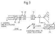
- the present invention is also applicable to fdm to tdm conversion in the optical domain, for example in an optical heterodyne coherent receiver, in which case the mixer comprises an optical detector which mixes a number of optical reference frequencies from a variable local oscillator 24, a laser for example, with the received optical fdm signal from the secondary stations 6 - as shown in Figure 3.
- the mixer comprises an optical detector which mixes a number of optical reference frequencies from a variable local oscillator 24, a laser for example, with the received optical fdm signal from the secondary stations 6 - as shown in Figure 3.
Landscapes
- Engineering & Computer Science (AREA)
- Computer Networks & Wireless Communication (AREA)
- Signal Processing (AREA)
- Optical Communication System (AREA)
- Time-Division Multiplex Systems (AREA)
- Transmitters (AREA)
- Stabilization Of Oscillater, Synchronisation, Frequency Synthesizers (AREA)
- Ac-Ac Conversion (AREA)
- Eye Examination Apparatus (AREA)
Applications Claiming Priority (2)
| Application Number | Priority Date | Filing Date | Title |
|---|---|---|---|
| GB878727847A GB8727847D0 (en) | 1987-11-27 | 1987-11-27 | Communication system |
| GB8727847 | 1987-11-27 |
Publications (2)
| Publication Number | Publication Date |
|---|---|
| EP0318334A1 true EP0318334A1 (de) | 1989-05-31 |
| EP0318334B1 EP0318334B1 (de) | 1994-11-30 |
Family
ID=10627658
Family Applications (1)
| Application Number | Title | Priority Date | Filing Date |
|---|---|---|---|
| EP88311257A Expired - Lifetime EP0318334B1 (de) | 1987-11-27 | 1988-11-28 | Vorrichtung und Verfahren zur Umsetzung eines Frequenzvielfachen in ein Zeitvielfaches |
Country Status (9)
| Country | Link |
|---|---|
| EP (1) | EP0318334B1 (de) |
| JP (1) | JP2694987B2 (de) |
| AT (1) | ATE114905T1 (de) |
| CA (1) | CA1334114C (de) |
| DE (1) | DE3852277T2 (de) |
| ES (1) | ES2064362T3 (de) |
| GB (1) | GB8727847D0 (de) |
| HK (1) | HK138096A (de) |
| WO (1) | WO1989005071A1 (de) |
Cited By (1)
| Publication number | Priority date | Publication date | Assignee | Title |
|---|---|---|---|---|
| EP0419120A2 (de) * | 1989-09-21 | 1991-03-27 | Smiths Industries Public Limited Company | Optische Multiplexierung |
Citations (4)
| Publication number | Priority date | Publication date | Assignee | Title |
|---|---|---|---|---|
| GB1297922A (de) * | 1969-11-25 | 1972-11-29 | ||
| EP0009534A1 (de) * | 1978-06-20 | 1980-04-16 | CSELT Centro Studi e Laboratori Telecomunicazioni S.p.A. | Wellenlängenmultiplexsystem mit vermindertem Übersprechen zwischen den einzelnen Kanälen |
| EP0033237A1 (de) * | 1980-01-24 | 1981-08-05 | Sperry Corporation | Multiplex-Vorrichtung für Nachrichtenerfassungssystem |
| EP0193190A2 (de) * | 1985-02-28 | 1986-09-03 | Alcatel SEL Aktiengesellschaft | Optisches Nachrichtenübertragungssystem im Teilnehmeranschlussbereich |
Family Cites Families (1)
| Publication number | Priority date | Publication date | Assignee | Title |
|---|---|---|---|---|
| JPH0669175B2 (ja) * | 1986-04-30 | 1994-08-31 | シャープ株式会社 | 多周波信号波形の処理方式 |
-
1987
- 1987-11-27 GB GB878727847A patent/GB8727847D0/en active Pending
-
1988
- 1988-11-25 CA CA000584226A patent/CA1334114C/en not_active Expired - Fee Related
- 1988-11-28 JP JP63509473A patent/JP2694987B2/ja not_active Expired - Lifetime
- 1988-11-28 WO PCT/GB1988/001039 patent/WO1989005071A1/en unknown
- 1988-11-28 AT AT88311257T patent/ATE114905T1/de not_active IP Right Cessation
- 1988-11-28 ES ES88311257T patent/ES2064362T3/es not_active Expired - Lifetime
- 1988-11-28 DE DE3852277T patent/DE3852277T2/de not_active Expired - Fee Related
- 1988-11-28 EP EP88311257A patent/EP0318334B1/de not_active Expired - Lifetime
-
1996
- 1996-07-25 HK HK138096A patent/HK138096A/xx not_active IP Right Cessation
Patent Citations (4)
| Publication number | Priority date | Publication date | Assignee | Title |
|---|---|---|---|---|
| GB1297922A (de) * | 1969-11-25 | 1972-11-29 | ||
| EP0009534A1 (de) * | 1978-06-20 | 1980-04-16 | CSELT Centro Studi e Laboratori Telecomunicazioni S.p.A. | Wellenlängenmultiplexsystem mit vermindertem Übersprechen zwischen den einzelnen Kanälen |
| EP0033237A1 (de) * | 1980-01-24 | 1981-08-05 | Sperry Corporation | Multiplex-Vorrichtung für Nachrichtenerfassungssystem |
| EP0193190A2 (de) * | 1985-02-28 | 1986-09-03 | Alcatel SEL Aktiengesellschaft | Optisches Nachrichtenübertragungssystem im Teilnehmeranschlussbereich |
Non-Patent Citations (1)
| Title |
|---|
| ELECTRONIC LETTERS, vol. 22, no. 12, 5th June 1986, pages 675-677, Hitchin, GB; N. SHIBATA et al.: " Crosstalk due to three-wave mixing process in a coherent single-mode transmission line" * |
Cited By (3)
| Publication number | Priority date | Publication date | Assignee | Title |
|---|---|---|---|---|
| EP0419120A2 (de) * | 1989-09-21 | 1991-03-27 | Smiths Industries Public Limited Company | Optische Multiplexierung |
| EP0419120A3 (en) * | 1989-09-21 | 1992-02-12 | Smiths Industries Public Limited Company | Optical multiplexing |
| US5216532A (en) * | 1989-09-21 | 1993-06-01 | Smiths Industries Public Limited Company | Optical multiplexing |
Also Published As
| Publication number | Publication date |
|---|---|
| CA1334114C (en) | 1995-01-24 |
| EP0318334B1 (de) | 1994-11-30 |
| ATE114905T1 (de) | 1994-12-15 |
| JP2694987B2 (ja) | 1997-12-24 |
| DE3852277D1 (de) | 1995-01-12 |
| WO1989005071A1 (en) | 1989-06-01 |
| JPH03502751A (ja) | 1991-06-20 |
| GB8727847D0 (en) | 1987-12-31 |
| DE3852277T2 (de) | 1995-04-06 |
| HK138096A (en) | 1996-08-02 |
| ES2064362T3 (es) | 1995-02-01 |
Similar Documents
| Publication | Publication Date | Title |
|---|---|---|
| US5323255A (en) | Transceiver arrangement using TDM to transmit assigned subcarrier waveforms | |
| CA1199074A (en) | Communications network with optical channels | |
| US4267590A (en) | Fiber-optical data-communication system using carriers of different wavelengths | |
| US7151896B2 (en) | Burst optical communication apparatus | |
| US6922431B1 (en) | Communication using spread spectrum methods over optical fibers | |
| JPS62206935A (ja) | 光通信機と光波信号送信方法 | |
| KR900007129B1 (ko) | 멀티 유저 통신 시스템 | |
| CA1269159A (en) | Switching techniques for fdm communication systems | |
| WO1986005343A1 (en) | Line transmission systems | |
| US4414663A (en) | Time division multiplex system having transmitted pulses in time channels distributed over and co-transmitted with a frame clock signal component | |
| US5406553A (en) | Apparatus and method for converting a frequency division multiplex to a time division multiplex | |
| EP0573913A1 (de) | Schaltungsanordnung zur Wellenlängenabstimmung und Taktsynchronisierung in einem optischen Nachrichtennetz sowie Wellenlängenmultiplexübertragungsnetz damit | |
| JP3031441B2 (ja) | 周波数チャネル内のメッセージ伝送方法及びメッセージ伝送ネットワーク | |
| JP3584072B2 (ja) | 通信ネットワーク及び通信局 | |
| EP0318334B1 (de) | Vorrichtung und Verfahren zur Umsetzung eines Frequenzvielfachen in ein Zeitvielfaches | |
| AU606241B2 (en) | Apparatus and method for converting a frequency division multiplex to a time division multiplex | |
| EP0389062A1 (de) | Übertragungssystem mit einer zentralen Leitstation und einer Anzahl dezentraler Stationen, über ein optisches Übertragungsnetzwerk mit dieser zentralen Zeitstation verbunden | |
| JP2738542B2 (ja) | コヒーレント光通信方式 | |
| JPH1032563A (ja) | ミリ波信号光多重伝送方式及び装置 | |
| JP3274873B2 (ja) | 光学的な周波数の相対的ポジショニング方法及び装置 | |
| JP2003218837A (ja) | 光無線システム及び無線基地局 | |
| RU2124812C1 (ru) | Способ передачи сигналов синхронных цифровых волоконно-оптических систем методом спектрально-кодового мультиплексирования и устройство для его осуществления | |
| JP2003037868A (ja) | 通信装置 | |
| JPS5813055B2 (ja) | デ−タとクロックの時分割多重伝送による光デ−タリンク方式 | |
| JPH0563656A (ja) | 波長同期型光処理装置及び該装置を用いた光路選択装置 |
Legal Events
| Date | Code | Title | Description |
|---|---|---|---|
| PUAI | Public reference made under article 153(3) epc to a published international application that has entered the european phase |
Free format text: ORIGINAL CODE: 0009012 |
|
| AK | Designated contracting states |
Kind code of ref document: A1 Designated state(s): AT BE CH DE ES FR GB GR IT LI LU NL SE |
|
| 17P | Request for examination filed |
Effective date: 19891107 |
|
| 17Q | First examination report despatched |
Effective date: 19911024 |
|
| GRAA | (expected) grant |
Free format text: ORIGINAL CODE: 0009210 |
|
| AK | Designated contracting states |
Kind code of ref document: B1 Designated state(s): AT BE CH DE ES FR GB GR IT LI LU NL SE |
|
| PG25 | Lapsed in a contracting state [announced via postgrant information from national office to epo] |
Ref country code: AT Effective date: 19941130 Ref country code: LI Effective date: 19941130 Ref country code: GR Free format text: LAPSE BECAUSE OF FAILURE TO SUBMIT A TRANSLATION OF THE DESCRIPTION OR TO PAY THE FEE WITHIN THE PRESCRIBED TIME-LIMIT Effective date: 19941130 Ref country code: BE Effective date: 19941130 Ref country code: CH Effective date: 19941130 |
|
| REF | Corresponds to: |
Ref document number: 114905 Country of ref document: AT Date of ref document: 19941215 Kind code of ref document: T |
|
| REF | Corresponds to: |
Ref document number: 3852277 Country of ref document: DE Date of ref document: 19950112 |
|
| EAL | Se: european patent in force in sweden |
Ref document number: 88311257.5 |
|
| ITF | It: translation for a ep patent filed | ||
| REG | Reference to a national code |
Ref country code: ES Ref legal event code: FG2A Ref document number: 2064362 Country of ref document: ES Kind code of ref document: T3 |
|
| REG | Reference to a national code |
Ref country code: CH Ref legal event code: PL |
|
| ET | Fr: translation filed | ||
| PLBE | No opposition filed within time limit |
Free format text: ORIGINAL CODE: 0009261 |
|
| STAA | Information on the status of an ep patent application or granted ep patent |
Free format text: STATUS: NO OPPOSITION FILED WITHIN TIME LIMIT |
|
| 26N | No opposition filed | ||
| PG25 | Lapsed in a contracting state [announced via postgrant information from national office to epo] |
Ref country code: LU Free format text: LAPSE BECAUSE OF NON-PAYMENT OF DUE FEES Effective date: 19951130 |
|
| PGFP | Annual fee paid to national office [announced via postgrant information from national office to epo] |
Ref country code: SE Payment date: 20001016 Year of fee payment: 13 |
|
| PGFP | Annual fee paid to national office [announced via postgrant information from national office to epo] |
Ref country code: NL Payment date: 20001020 Year of fee payment: 13 |
|
| PGFP | Annual fee paid to national office [announced via postgrant information from national office to epo] |
Ref country code: ES Payment date: 20001107 Year of fee payment: 13 |
|
| PGFP | Annual fee paid to national office [announced via postgrant information from national office to epo] |
Ref country code: FR Payment date: 20011012 Year of fee payment: 14 |
|
| PGFP | Annual fee paid to national office [announced via postgrant information from national office to epo] |
Ref country code: DE Payment date: 20011029 Year of fee payment: 14 |
|
| PG25 | Lapsed in a contracting state [announced via postgrant information from national office to epo] |
Ref country code: ES Free format text: LAPSE BECAUSE OF NON-PAYMENT OF DUE FEES Effective date: 20011129 Ref country code: SE Free format text: LAPSE BECAUSE OF NON-PAYMENT OF DUE FEES Effective date: 20011129 |
|
| REG | Reference to a national code |
Ref country code: GB Ref legal event code: IF02 |
|
| PG25 | Lapsed in a contracting state [announced via postgrant information from national office to epo] |
Ref country code: NL Free format text: LAPSE BECAUSE OF NON-PAYMENT OF DUE FEES Effective date: 20020601 |
|
| EUG | Se: european patent has lapsed |
Ref document number: 88311257.5 |
|
| NLV4 | Nl: lapsed or anulled due to non-payment of the annual fee |
Effective date: 20020601 |
|
| PG25 | Lapsed in a contracting state [announced via postgrant information from national office to epo] |
Ref country code: DE Free format text: LAPSE BECAUSE OF NON-PAYMENT OF DUE FEES Effective date: 20030603 |
|
| PG25 | Lapsed in a contracting state [announced via postgrant information from national office to epo] |
Ref country code: FR Free format text: LAPSE BECAUSE OF NON-PAYMENT OF DUE FEES Effective date: 20030731 |
|
| REG | Reference to a national code |
Ref country code: FR Ref legal event code: ST |
|
| REG | Reference to a national code |
Ref country code: ES Ref legal event code: FD2A Effective date: 20021213 |
|
| PG25 | Lapsed in a contracting state [announced via postgrant information from national office to epo] |
Ref country code: IT Free format text: LAPSE BECAUSE OF NON-PAYMENT OF DUE FEES Effective date: 20051128 |
|
| PGFP | Annual fee paid to national office [announced via postgrant information from national office to epo] |
Ref country code: GB Payment date: 20071018 Year of fee payment: 20 |
|
| REG | Reference to a national code |
Ref country code: GB Ref legal event code: PE20 Expiry date: 20081127 |
|
| PG25 | Lapsed in a contracting state [announced via postgrant information from national office to epo] |
Ref country code: GB Free format text: LAPSE BECAUSE OF EXPIRATION OF PROTECTION Effective date: 20081127 |