EP0317837B1 - Common drive for shutter blades and objective lens assembly - Google Patents
Common drive for shutter blades and objective lens assembly Download PDFInfo
- Publication number
- EP0317837B1 EP0317837B1 EP88118756A EP88118756A EP0317837B1 EP 0317837 B1 EP0317837 B1 EP 0317837B1 EP 88118756 A EP88118756 A EP 88118756A EP 88118756 A EP88118756 A EP 88118756A EP 0317837 B1 EP0317837 B1 EP 0317837B1
- Authority
- EP
- European Patent Office
- Prior art keywords
- blade
- blade member
- lens element
- lens
- camera
- Prior art date
- Legal status (The legal status is an assumption and is not a legal conclusion. Google has not performed a legal analysis and makes no representation as to the accuracy of the status listed.)
- Expired - Lifetime
Links
- 230000007246 mechanism Effects 0.000 claims description 46
- 230000008878 coupling Effects 0.000 claims description 16
- 238000010168 coupling process Methods 0.000 claims description 16
- 238000005859 coupling reaction Methods 0.000 claims description 16
- 238000006073 displacement reaction Methods 0.000 claims description 16
- 230000000903 blocking effect Effects 0.000 claims description 13
- 230000011514 reflex Effects 0.000 claims description 12
- 230000000750 progressive effect Effects 0.000 claims description 8
- 230000004044 response Effects 0.000 claims description 5
- 150000001875 compounds Chemical class 0.000 claims description 4
- 238000000034 method Methods 0.000 claims description 4
- 230000003247 decreasing effect Effects 0.000 claims description 2
- 230000005540 biological transmission Effects 0.000 claims 2
- 230000000875 corresponding effect Effects 0.000 claims 2
- 230000001276 controlling effect Effects 0.000 claims 1
- 230000002596 correlated effect Effects 0.000 claims 1
- 238000009432 framing Methods 0.000 claims 1
- 230000001939 inductive effect Effects 0.000 claims 1
- 230000000977 initiatory effect Effects 0.000 description 4
- XEEYBQQBJWHFJM-UHFFFAOYSA-N Iron Chemical compound [Fe] XEEYBQQBJWHFJM-UHFFFAOYSA-N 0.000 description 2
- 230000008859 change Effects 0.000 description 2
- 238000010586 diagram Methods 0.000 description 2
- 239000004020 conductor Substances 0.000 description 1
- 230000000694 effects Effects 0.000 description 1
- 238000010304 firing Methods 0.000 description 1
- 229910052742 iron Inorganic materials 0.000 description 1
- 230000004048 modification Effects 0.000 description 1
- 238000012986 modification Methods 0.000 description 1
- 238000012544 monitoring process Methods 0.000 description 1
- 230000003287 optical effect Effects 0.000 description 1
- 230000000717 retained effect Effects 0.000 description 1
Images



Classifications
-
- G—PHYSICS
- G02—OPTICS
- G02B—OPTICAL ELEMENTS, SYSTEMS OR APPARATUS
- G02B7/00—Mountings, adjusting means, or light-tight connections, for optical elements
- G02B7/28—Systems for automatic generation of focusing signals
- G02B7/40—Systems for automatic generation of focusing signals using time delay of the reflected waves, e.g. of ultrasonic waves
-
- G—PHYSICS
- G02—OPTICS
- G02B—OPTICAL ELEMENTS, SYSTEMS OR APPARATUS
- G02B7/00—Mountings, adjusting means, or light-tight connections, for optical elements
- G02B7/28—Systems for automatic generation of focusing signals
Definitions
- the present invention relates to a common shutter blade and lens focusing system drive for a photographic camera, in general, and to such a drive for a single lens reflex camera employing a scanning blade type shutter, in particular.
- Photographic apparatus employing shutter blade mechanisms, in general, and scanning blade shutters, in particular, as well as a lens mechanism that may be automatically focused in accordance with a rangefinder-determined camera-to-subject distance are well known in the art.
- a camera employing a scanning blade shutter and a lens mechanism responsive to a rangefinder-determined subject distance signal is described in, for example, U.S. Patent No. 4,192,587, entitled “Proportioned Fill Flash", by A. G. La Rocque, et al, issued March 11, 1980, in common assignment herewith.
- the disclosure in said LaRocque et al patent is specifically incorporated herein by reference.
- Scanning shutter blade mechanisms are normally driven from a scene light blocking position toward a maximum aperture defining position and thereafter returned to their initial scene light blocking position during an exposure interval.
- Such scanning blade shutter mechanisms generally comprise a pair of scanning blade shutter elements each having a primary aperture therethrough. The shutter blade elements overlap for reciprocal movement with respect to each other. This movement drives the primary aperture into overlapping relationship with each other so as to define a progressively increasing and then decreasing effective primary aperture.
- the shutter blade mechanisms are normally driven by a spring and solenoid arrangement as shown in La Rocque et al, supra, or by a microcomputer controlled stepper motor incorporating a digitally encoded scanning blade position sensor as shown, for example, in U.S. Patent No. 4,325,614, entitled "Exposure Control System With Shutter Operation Controlled by a Microcomputer", by D. L. Grimes, issued April 20, 1982, in common assignment herewith.
- Autofocus cameras of the aforementioned type generally embody a motor driven objective lens mechanism which must be stopped at an appropriate focal position corresponding to a previously determined camera to-subject distance.
- a lens position encoder system to identify the instantaneous focal position of a lens element driven by said lens mechanism as it is moved through its plurality of different focal positions in order to precisely position the lens element at a previously determined object-distance-related focal position as shown, for example, in La Rocque et al, supra.
- the objective lens and shutter blade mechanisms are driven by a common drive that either sequentially drives the objective lens and the shutter blades or are driven by separate shutter blade and lens drive means.
- U.S. Patent No. 4,278,340 to Toyama et al is an example of such a sequential lens and shutter blade drive
- U.S. Patent No. 4,199,244 to Shenk is an example of a camera employing separate shutter blade and lens drives.
- an encoder system were to be employed in such cameras to determine the instantaneous focal position of the movable lens element as in, for example, La Rocque et al, supra, and the instantaneous blade position of the scanning shutter blades as in, for example, Grimes, supra, the prior art teaches the use of separate encoders for each such position sensing function.
- the use of duplicate drive means and encoders in an autofocus camera necessarily increases camera cost, size and complexity.
- a photographic camera in accordance with the preamble of claim 1 is known from GB-A-2 097 138.
- the present invention further provides a rangefinder-derived signal-responsive common drive that is capable of simultaneously driving both the shutter and focusing mechanisms in a single lens reflex camera.
- the present invention further provides a single position-encoder that is capable of determining both the instantaneous blade position of a shutter blade mechanism and the instantaneous focal position of the movable lens element in an adjustable focus lens camera.
- the invention also relates to a photographic method as claimed in claims 15 and 16.
- a single or common drive is provided that is capable of actuating both the objective lens and shutter and/or aperture mechanisms in an adjustable focus lens camera to a lens focal position corresponding to a previously determined camera-to-subject distance or other desired focal position and through an exposure interval, respectively.
- the shutter is directly coupled to the common drive and the objective lens mechanism is coupled to the common drive through a drive link assembly. Actuation of the common drive moves the initially open shutter mechanism towards its closed or light-blocking position and moves the objective lens mechanism coupled thereto by said drive link assembly toward a previously determined lens focal position.
- Means coupled to the drive link assembly and responsive to a signal representative of said previously determined camera-to-subject distance actuates said drive link assembly to uncouple the objective lens mechanism from the common drive when said lens mechanism has been moved to a focal position corresponding to said previously determined camera-to-subject distance.
- the common drive subsequently moves the shutter mechanism to its full closed position prior to the initiation of a film exposure interval.
- the drive link assembly connection between the common drive and said objective lens mechanism is re-established subsequent to a film exposure interval to thereby enable the common drive to return the objective lens mechanism to its initial focal position while moving the shutter to its initial open position.
- Fig. 1 is a block diagram showing a photographic camera embodying the combination lens and shutter drive of the present invention.
- Fig. 2 is a front elevational view of the scanning shutter blades and associated drive mechanism of the present invention.
- Fig. 3 is a sectional view taken on the line 3-3 in drawing Fig. 2.
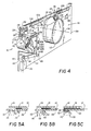
- Fig. 4 is a diagrammatic perspective view of the lens and associated lens drive mechanism of the present invention showing portions thereof removed to reveal otherwise hidden structure.
- Figs. 5A, 5B and 5C are sectional views taken on the line 5-5 in drawing Fig. 4 sequentially showing the lens-to-drive coupling means in an uncoupled, a transitional and a coupled state, respectively.
- Fig. 6 is a timeline showing a typical operational sequence of various lens and shutter drive related elements in the camera of Figs. 1-5.
- FIG. 10 a block diagram of a photographic camera incorporating a preferred embodiment of the combination lens and shutter drive mechanism of the present invention.
- Camera 10 is of the single lens reflex type and said camera includes housing 12 within which film is supported at focal plane 14 opposite hub 16.
- Lens assembly or lens mount 18 is positioned within hub 16 and is displaceable in axial direction 20 to form an in-focus image of subject 22 at said plane 14 when shutter mechanism 24 is actuated to generate an exposure interval after mirror 26 has been moved from its vertical or viewing position to its horizontal or film exposure position (shown in phantom) as functionally illustrated in said drawing Fig. 1.
- Exemplary of a single lens reflex camera of the type described above is U.S. Patent No. 3,714,879 to Land et al. and of the above-described displaceable or adjustable focus lens camera is the U.S. Patent to Shenk, supra.
- Shutter mechanism 24 is driven by shutter/lens drive 30 through path 32 in response to drive signals from exposure and focus control 34 in a closed loop system that includes shutter blade position sensor 36, under the control of microcomputer 37.
- Lens mount 18 is also driven by said shutter/lens drive 30 through coupling means 38.
- Coupling means 38 is actuated between its coupled and uncoupled states by coupling operator 40 in response to coupling means control signals from exposure and focus control 34.
- mirror 26 is actuated between its viewing and film exposure positions by mirror operator 42 and strobe flash 44 is fired, in response to mirror position control signals and flash fire signals, respectively, from said exposure and focus control 34.
- the coupling operator 40, the mirror operator 42 control signals and the flash fire signals from exposure and focus control 34 are also under the control of said microcomputer 37.
- Microcomputer 37 is, in turn, responsive to a plurality of inputs. These include manual start input 46 provided in response to an operator manually actuating an exposure cycle start button and automatically provided inputs such as pre-exposure and exposure interval scene brightness conditions, designated 48, and a camera-to-scene distance input, designated 50, which is preferably provided by a sonar ranging system of the type disclosed in commonly assigned U.S. Patent No. 4,081,626 to Muggli et al. Microcomputer 37 stores a plurality of selectable blade trajectory programs in a manner similar to that described in U.S. Patent No. 4,427,276 to Feinerman et al and the implementation of any one particular trajectory program is automatically determined, in part, by such microcomputer 37 inputs as rangefinder determined subject distance and scene brightness conditions.
- Shutter mechanism 24 functionally illustrated in drawing Fig. 1, is of the scanning shutter blade type, and is shown in much greater detail in drawing Fig. 2.
- Fig. 2 is a front elevational view of the scanning blade shutter forming said shutter mechanism 24.
- shutter mechanism 24 comprises two overlapping shutter blade elements 52, 54 disposed for reciprocal sliding movement with respect to one another on baseblock 56.
- Shutter blade elements 52, 54 are respectively provided with scene light admitting primary apertures 58 and 60 to collectively define a progressive variation of effective aperture opening 62 in accordance with the simultaneous longitudinal and lateral displacement of one blade element with respect to the other blade element in a manner as is fully described in U.S. Patent No. 3,942,183, entitled "Camera With Pivoting Blades" by George D.
- Effective aperture 62 may be varied between a light blocking and an infinite number of light unblocking positions and is shown in Fig. 2 in its fully open, light unblocking position.
- the primary apertures 58, 60 are selectively shaped and positioned so as to overlap and form a light entry exposure aperture 62 in baseblock 56 to thereby define said effective aperture 62, of varying size, as a function of the position of blade elements 52, 54.
- pivot pin or stud 64 Projecting from the baseblock 56 at a location spaced laterally apart from light entry exposure aperture 62 in drawing Fig. 2 is pivot pin or stud 64 which pivotally and translatably engages slots 66 and 68 respectively formed near one end of shutter blade elements 52, 54.
- Pin 64 may be integrally formed with the baseblock 56 and blade elements 52, 54 may be retained in engaging relation with respect to the pin 64 by any suitable retaining means.
- the opposite ends of blade elements 52, 54 include extended portions 70 and 72, respectively, which pivotally connect to opposite ends of walking beam member 74.
- Walking beam 74 is integrally formed with and is located at one end of rotor 78 of galvanometer actuator 80 and said actuator 80 is mounted in a fixed position with respect to said baseblock 56.
- walking beam 74 is pivotally connected at its distal ends to the shutter blade elements 52, 54 by coupling pins 82, 84, respectively.
- Galvanometer actuator 80 provides the drive force required to displace scanning shutter blades 52, 54 with respect to each other and with respect to baseblock 56 over their complete aperture-forming operational range.
- Galvanometer actuator 80 is, in effect, a combination d'Arsonval galvanometer and a DC electric motor.
- Galvanometer actuator 80 includes cylindrically shaped permanent magnet 86 formed of magnetic segments, supported in cylindrically shaped soft iron support structure, that is mounted in a fixed position with respect to camera housing 12 (Fig. 1).
- the rotor 78, having multiple turn coil 88 wound thereon is mounted for rotation within cylindrically shaped magnet 86 and within the magnetic field of said permanent magnet 86.
- a rotational force is generated by multiple turn coil 88 and rotor 78 on which said coil 88 is wound in either a clockwise or counterclockwise direction when a DC current having a particular magnitude and direction is passed through said coil 88 by exposure and focus control 34 (Fig. 1) under the control of microcomputer 37 (Fig. 1).
- Galvanometer actuator 80 has some of the characteristics of an electric motor i.e. it utilizes the forces produced by a magnetic field on a current-carrying conductor and some of the characteristics of a galvanometer i.e. the rotor rotates less than one complete revolution when actuated to drive shutter blade elements 52, 54 between their scene light blocking and unblocking positions.
- Shutter blade mechanism 24 is provided with analog-type, blade displacement sensing encoder system 36 for continuously monitoring the position of shutter blade elements 52, 54 during the course of an exposure interval.
- encoder system 36 preferably includes laterally extending rectangular and triangular shaped secondary apertures 92, 94 respectively formed in scanning blades 52, 54 for movement therewith.
- secondary apertures 92, 94 collectively define a progressive variation of effective secondary aperture opening 96 in accordance with the simultaneous lateral displacement of blade element 52 with respect to blade element 54.
- encoder system 36 additionally includes light emitting diode 98 and light sensing diode 100 mounted on opposite sides of the combination of shutter blades 52, 54 and lens mounting plate 108 (Fig. 4).
- light emitted by light emitting diode 98 is directed to light sensing diode 100 through effective secondary aperture opening 96 by reflecting mirror 102 and lens 104.
- Light emitting diode 98 is energized prior to the initiation of a film exposure cycle actuating shutter blade mechanism 24.
- Actuation of shutter blades 52, 54 of said shutter mechanism 24 by galvanometer actuator 80 causes a change in the size of effective secondary aperture opening 96 which, in turn, causes a progressive change in the amount of light light sensed by the photosensitive surface of light sensing diode 100 through aperture opening 96.
- An electrical signal representative of the instantaneous position of shutter blade elements 52, 54 in the form of an electrical current is generated by light sensing diode 100 in correspondence with the amount of light sensed by said diode 100.
- This shutter blade position signal is subsequently transmitted by shutter blade position sensing encoder 36 to exposure and focus control 34 (Fig. 1) through path 106.
- lens mounting plate 108 is mounted in a fixed position with respect to camera housing 12 (Fig. 1), immediately in front of galvanometer actuator 80, walking beam 74 and shutter blades 52, 54.
- Adjustable focus lens assembly 110 is mounted in a fixed position on said lens plate 108.
- Lens assembly 110 includes front lens element 112 that is translatable along optical axis 114 by a conventional cam ring where it serves to focus images of subjects positioned in various locations within a range of subject distances at image plane 14 (Fig. 1) of said single lens reflex camera 10.
- Drive link 116 is attached to lens mounting plate 108 by pins 118A and 118B projecting from said drive link 116 and through laterally extending elongated slots 120A and 120B, respectively, for reciprocating movement with respect to said mounting plate 108.
- a portion of the lower edge of drive link 116 is formed with a gear rack 122 that is meshed with smaller gear 124 of compound gear 126 rotatably mounted on said lens mounting plate 108.
- Larger gear 128 of said compound gear 126 is, in turn, in mesh with gear 130 formed in the periphery of conventional lens element translating cam ring 131 of lens assembly 110.
- Latch 132 is attached to that end of drive link 116 remote from gear rack 122, for rotation about latch axis 134.
- Latch 132 is provided with bifurcation or open slot 136 at one end and lever arm 138 at the other.
- a spring (not shown) is provided to resist (i.e., to provide a biasing force against) the rotation of latch 132 about latch axis 134 in direction 140.
- Pin 142 projecting from the upper end of walking beam member 74 extends through arcuate clearance slot 144 in mounting plate 108 for limited arcuate movement therein. Pin 142 engages open slot 136 in latch 132 for pivotal movement therein when walking beam member 74 is actuated to drive link 116 through said latch 132. If latch 132 is rotated in direction 140, open slot 136 will move out of engagement with walking beam pin 142. Subsequent rotational movement of walking beam member 74 after slot 136 has been so disengaged, will not be transmitted to drive link 116 nor to front lens element 112 of lens assembly 110 coupled thereto.
- FIG. 5A which is a sectional view taken on the line 5-5 in drawing Fig. 4 illustrates such movement.
- pin 142 projecting from walking beam 74 has moved laterally away from latch slot 136 and then latch 132, now in its unlatch state, has been springforce biased back to its initial rotational position or the rotational position it assumes when in its walking beam 74 to drive link 116 latch state.
- the mechanical link between said latch 132 and walking beam 74 is re-established in the following manner as additionally illustrated in drawing Figs. 5B and 5C.
- Figs. 5B and 5C are also sectional views taken on the line 5-5 in drawing Fig. 4.
- galvanometer actuator 80 (Fig. 4) initially drives pin 142 projecting from walking beam member 74 toward latch 132.
- Pin 142 is subsequently driven into cam surface 146 of latch 132, thereby causing the slot 136 portion of latch 132 to cam outward in direction 148 away from mounting plate 108.
- pin 142 continues to move toward latch 132, it ultimately becomes aligned with slot portion 136 thereof, as shown in drawing Fig. 5C, thereby enabling slot 136 to pivot inward in direction 150 under the force of the above-noted force bias spring (not shown) of latch 132 to thereby mechanically couple said walking beam member 74 to drive link 116.
- electrically actuated solenoid 152 is attached, in a fixed position, to lens mounting plate 108 and pivot link 154 is rotatably attached to said plate 108 by pin 156.
- L-shaped slide link 158 is attached to mounting plate 108 by pins 160A and 160B projecting from said plate 108 through vertically extending, elongated slide link slots 162A and 162B, respectively, for reciprocating vertical movement with respect to said mounting plate 108.
- Pin 164 projecting from one end of pivot link 154 engages slot 166 in solenoid armature 168 for pivotal movement therein and the other end of said pivot link 154 is, in turn, pivotally attached to the lower end of said slide link 158 by pin 169.
- Arm 170 of slide link 158 at the upper end of said link 158 is in sliding contact with the bottom surface of the lever arm 138 portion of latch 132.
- the function of link arm 170 is to maintain contact between slide link 158 and latch arm 138 whenever drive link 116 moves in slots 120A and 120B relative to said slide link 158.
- electrical solenoid 152 When electrical solenoid 152 is energized, armature portion 168 is electromagnetically attracted downward, causing pivot link 154 to rotate about pin 156 and thereby cause link 158 to slide upward on support pins 160A, 160B.
- This upward motion of slide link 158 is transferred to lever arm 138 through link arm 170, causing latch 132 to rotate in direction 140 and thereby uncouple drive link 116 from walking beam member 74.
- FIG. 1-5 is a time line showing the sequence of operation of various lens and shutter drive related elements of single lens reflex camera 10.
- shutter mechanism 24 is in its full open position, walking beam member 74 is mechanically coupled to drive link 116 through latch 132 and mirror 26 is in its viewing or blocking position precluding any and all scene light from reaching image plane 14.
- a lens focusing and film exposure sequence is initiated by an operator actuation of manual start 46.
- the actuation of manual start 46 causes initial scene brightness conditions to be determined by light sensing means (not shown) within scene brightness condition determining means 48 and causes rangefinder 50 to ultrasonically produce an electrical signal representative of subject distance.
- exposure and focus control 34 under the control of microcomputer 37 generates a forward shutter/lens drive signal causing galvanometer actuator 80 to translate front lens element 112, through drive link 116, to the focus position determined by rangefinder 50.
- the focus position of lens element 112 is sensed by shutter blade encoder system 36 in that blades 52, 54 are directly coupled to said lens element 112 through walking beam member 74 and drive link 116.
- solenoid 152 When lens element 112 of lens assembly 110 has been driven to the desired focal position just prior to t2 by galvanometer actuator 80, solenoid 152 is energized at t2 by exposure and focus control 34, causing the downward movement of solenoid armature 168 to rotate pivot link 154 about pin 156 and slide link 158 to move vertically upward on pins 160A and 160B.
- the upward movement of slide link 158 is transferred to arm 138 of latch 132 by arm 170 of slide link 158 to thereby rotate latch 132 out of engagement with walking beam 74 as said latch 132 is rotated in direction 140 by such slide link 158 movement.
- galvanometer actuator 80 moving in the same direction, drives shutter mechanism 24 to its full closed position at t3. It should be noted that the forward drive signal to galvactuator 80 is interrupted just prior to t2 or when lens element 112 has reached the desired focal position, and during the period of time that walking beam 74 is being uncoupled from drive link 116.
- Mirror 26 is actuated to its unblocking position between times t3 and t4 by mirror operator 42 and microcomputer controlled exposure and focus control 34.
- a shutter mechanism 24 actuating exposure interval is initiated at t5 and terminated at t6 by exposure and focus control 34 in correspondence with the blade aperture size versus time trajectory program stored within microcomputer 37 that, if the sensed lighting conditions deem it necessary, includes the firing of scene illuminating strobe flash 44.
- Mirror 26 is then returned to its scene light blocking position between t7 and t8 and coupling operator 40 is enabled by de-energizing solenoid 152 at said time t8.
- a reverse shutter/lens drive signal is also generated by microcomputer controlled exposure and focus control 34 causing galvanometer actuator 80 to drive shutter blades 52, 54 in shutter mechanism 24 toward their open or light unblocking positions.
- pin 142 projecting from galvactuator coupled walking beam 74 engages cam surface 142 (Fig. 5B) of latch 132, causing slot 136 formed therein to pivot outward in direction 148 away from lens mounting plate 108.
- said pin 142 becomes aligned or is moved into registration with latch slot 136.
- the said slotted end of latch 136 is pivoted inward in direction 150 (Fig. 5C) under the force of the latch 132 bias spring (not shown) as said walking beam 142 enters said slot 136.
- a single actuator (galvanometer actuator 80) has been employed to simultaneously drive the blade elements of a shutter mechanism while at the same time driving the movable element of an adjustable focus lens to a desired focus position during at least a portion of the shutter blade actuation cycle.
- movable element 112 of lens assembly 110 and all of the means coupling said lens element to walking beam 74 are uncoupled from said walking beam 74 prior to the initiation of an image forming exposure interval.
Landscapes
- Physics & Mathematics (AREA)
- General Physics & Mathematics (AREA)
- Optics & Photonics (AREA)
- Shutters For Cameras (AREA)
- Focusing (AREA)
- Automatic Focus Adjustment (AREA)
Description
- The present invention relates to a common shutter blade and lens focusing system drive for a photographic camera, in general, and to such a drive for a single lens reflex camera employing a scanning blade type shutter, in particular.
- Photographic apparatus employing shutter blade mechanisms, in general, and scanning blade shutters, in particular, as well as a lens mechanism that may be automatically focused in accordance with a rangefinder-determined camera-to-subject distance are well known in the art. A camera employing a scanning blade shutter and a lens mechanism responsive to a rangefinder-determined subject distance signal is described in, for example, U.S. Patent No. 4,192,587, entitled "Proportioned Fill Flash", by A. G. La Rocque, et al, issued March 11, 1980, in common assignment herewith. For convenience, the disclosure in said LaRocque et al patent is specifically incorporated herein by reference.
- Scanning shutter blade mechanisms are normally driven from a scene light blocking position toward a maximum aperture defining position and thereafter returned to their initial scene light blocking position during an exposure interval. Such scanning blade shutter mechanisms generally comprise a pair of scanning blade shutter elements each having a primary aperture therethrough. The shutter blade elements overlap for reciprocal movement with respect to each other. This movement drives the primary aperture into overlapping relationship with each other so as to define a progressively increasing and then decreasing effective primary aperture. The shutter blade mechanisms are normally driven by a spring and solenoid arrangement as shown in La Rocque et al, supra, or by a microcomputer controlled stepper motor incorporating a digitally encoded scanning blade position sensor as shown, for example, in U.S. Patent No. 4,325,614, entitled "Exposure Control System With Shutter Operation Controlled by a Microcomputer", by D. L. Grimes, issued April 20, 1982, in common assignment herewith.
- Autofocus cameras of the aforementioned type generally embody a motor driven objective lens mechanism which must be stopped at an appropriate focal position corresponding to a previously determined camera to-subject distance. In such cameras, it is desirable to provide a lens position encoder system to identify the instantaneous focal position of a lens element driven by said lens mechanism as it is moved through its plurality of different focal positions in order to precisely position the lens element at a previously determined object-distance-related focal position as shown, for example, in La Rocque et al, supra.
- In prior adjustable focus lens camera employing scanning shutter blades, the objective lens and shutter blade mechanisms are driven by a common drive that either sequentially drives the objective lens and the shutter blades or are driven by separate shutter blade and lens drive means. U.S. Patent No. 4,278,340 to Toyama et al is an example of such a sequential lens and shutter blade drive and U.S. Patent No. 4,199,244 to Shenk is an example of a camera employing separate shutter blade and lens drives. In addition, if an encoder system were to be employed in such cameras to determine the instantaneous focal position of the movable lens element as in, for example, La Rocque et al, supra, and the instantaneous blade position of the scanning shutter blades as in, for example, Grimes, supra, the prior art teaches the use of separate encoders for each such position sensing function. The use of duplicate drive means and encoders in an autofocus camera necessarily increases camera cost, size and complexity.
- A photographic camera in accordance with the preamble of claim 1 is known from GB-A-2 097 138.
- It is a primary object of the present invention, therefore, to provide an improved photographic camera that is capable of driving the movable element of an adjustable focus lens to a previously determined lens focal position and of driving a scanning blade type shutter mechanism during an exposure interval.
- Said technical problem is solved by the characterizing features of claim 1.
- Further features are specified in subclaims 2-14.
- The present invention further provides a rangefinder-derived signal-responsive common drive that is capable of simultaneously driving both the shutter and focusing mechanisms in a single lens reflex camera.
- The present invention further provides a single position-encoder that is capable of determining both the instantaneous blade position of a shutter blade mechanism and the instantaneous focal position of the movable lens element in an adjustable focus lens camera.
- The invention also relates to a photographic method as claimed in
claims 15 and 16. - Other objects and/or advantages of our invention will be made readily apparent by referring to the preferred embodiments thereof described in detail blow.
- In accordance with the present invention, a single or common drive is provided that is capable of actuating both the objective lens and shutter and/or aperture mechanisms in an adjustable focus lens camera to a lens focal position corresponding to a previously determined camera-to-subject distance or other desired focal position and through an exposure interval, respectively. The shutter is directly coupled to the common drive and the objective lens mechanism is coupled to the common drive through a drive link assembly. Actuation of the common drive moves the initially open shutter mechanism towards its closed or light-blocking position and moves the objective lens mechanism coupled thereto by said drive link assembly toward a previously determined lens focal position. Means coupled to the drive link assembly and responsive to a signal representative of said previously determined camera-to-subject distance actuates said drive link assembly to uncouple the objective lens mechanism from the common drive when said lens mechanism has been moved to a focal position corresponding to said previously determined camera-to-subject distance. The common drive subsequently moves the shutter mechanism to its full closed position prior to the initiation of a film exposure interval. The drive link assembly connection between the common drive and said objective lens mechanism is re-established subsequent to a film exposure interval to thereby enable the common drive to return the objective lens mechanism to its initial focal position while moving the shutter to its initial open position.
- Fig. 1 is a block diagram showing a photographic camera embodying the combination lens and shutter drive of the present invention.
- Fig. 2 is a front elevational view of the scanning shutter blades and associated drive mechanism of the present invention.
- Fig. 3 is a sectional view taken on the line 3-3 in drawing Fig. 2.
- Fig. 4 is a diagrammatic perspective view of the lens and associated lens drive mechanism of the present invention showing portions thereof removed to reveal otherwise hidden structure.
- Figs. 5A, 5B and 5C are sectional views taken on the line 5-5 in drawing Fig. 4 sequentially showing the lens-to-drive coupling means in an uncoupled, a transitional and a coupled state, respectively.
- Fig. 6 is a timeline showing a typical operational sequence of various lens and shutter drive related elements in the camera of Figs. 1-5.
- Referring now to Fig. 1 of the drawings, there is shown at 10 a block diagram of a photographic camera incorporating a preferred embodiment of the combination lens and shutter drive mechanism of the present invention. Camera 10 is of the single lens reflex type and said camera includes
housing 12 within which film is supported atfocal plane 14opposite hub 16. Lens assembly orlens mount 18 is positioned withinhub 16 and is displaceable in axial direction 20 to form an in-focus image ofsubject 22 at saidplane 14 whenshutter mechanism 24 is actuated to generate an exposure interval aftermirror 26 has been moved from its vertical or viewing position to its horizontal or film exposure position (shown in phantom) as functionally illustrated in said drawing Fig. 1. Exemplary of a single lens reflex camera of the type described above is U.S. Patent No. 3,714,879 to Land et al. and of the above-described displaceable or adjustable focus lens camera is the U.S. Patent to Shenk, supra. -
Shutter mechanism 24 is driven by shutter/lens drive 30 throughpath 32 in response to drive signals from exposure andfocus control 34 in a closed loop system that includes shutterblade position sensor 36, under the control ofmicrocomputer 37.Lens mount 18 is also driven by said shutter/lens drive 30 through coupling means 38. Coupling means 38 is actuated between its coupled and uncoupled states bycoupling operator 40 in response to coupling means control signals from exposure andfocus control 34. Similarly,mirror 26 is actuated between its viewing and film exposure positions bymirror operator 42 andstrobe flash 44 is fired, in response to mirror position control signals and flash fire signals, respectively, from said exposure andfocus control 34. Thecoupling operator 40, themirror operator 42 control signals and the flash fire signals from exposure andfocus control 34 are also under the control of saidmicrocomputer 37. -
Microcomputer 37 is, in turn, responsive to a plurality of inputs. These includemanual start input 46 provided in response to an operator manually actuating an exposure cycle start button and automatically provided inputs such as pre-exposure and exposure interval scene brightness conditions, designated 48, and a camera-to-scene distance input, designated 50, which is preferably provided by a sonar ranging system of the type disclosed in commonly assigned U.S. Patent No. 4,081,626 to Muggli et al. Microcomputer 37 stores a plurality of selectable blade trajectory programs in a manner similar to that described in U.S. Patent No. 4,427,276 to Feinerman et al and the implementation of any one particular trajectory program is automatically determined, in part, bysuch microcomputer 37 inputs as rangefinder determined subject distance and scene brightness conditions. -
Shutter mechanism 24 functionally illustrated in drawing Fig. 1, is of the scanning shutter blade type, and is shown in much greater detail in drawing Fig. 2. Fig. 2 is a front elevational view of the scanning blade shutter forming saidshutter mechanism 24. With respect to Fig. 2,shutter mechanism 24 comprises two overlappingshutter blade elements baseblock 56.Shutter blade elements primary apertures Effective aperture 62 may be varied between a light blocking and an infinite number of light unblocking positions and is shown in Fig. 2 in its fully open, light unblocking position. Theprimary apertures entry exposure aperture 62 inbaseblock 56 to thereby define saideffective aperture 62, of varying size, as a function of the position ofblade elements - Projecting from the
baseblock 56 at a location spaced laterally apart from lightentry exposure aperture 62 in drawing Fig. 2 is pivot pin orstud 64 which pivotally and translatably engagesslots shutter blade elements Pin 64 may be integrally formed with thebaseblock 56 andblade elements pin 64 by any suitable retaining means. The opposite ends ofblade elements extended portions walking beam member 74.Walking beam 74, in turn, is integrally formed with and is located at one end ofrotor 78 ofgalvanometer actuator 80 and saidactuator 80 is mounted in a fixed position with respect to saidbaseblock 56. In the preferred embodiment,walking beam 74 is pivotally connected at its distal ends to theshutter blade elements coupling pins -
Galvanometer actuator 80 provides the drive force required to displacescanning shutter blades baseblock 56 over their complete aperture-forming operational range.Galvanometer actuator 80 is, in effect, a combination d'Arsonval galvanometer and a DC electric motor.Galvanometer actuator 80 includes cylindrically shapedpermanent magnet 86 formed of magnetic segments, supported in cylindrically shaped soft iron support structure, that is mounted in a fixed position with respect to camera housing 12 (Fig. 1). Therotor 78, havingmultiple turn coil 88 wound thereon is mounted for rotation within cylindrically shapedmagnet 86 and within the magnetic field of saidpermanent magnet 86. A rotational force is generated bymultiple turn coil 88 androtor 78 on which saidcoil 88 is wound in either a clockwise or counterclockwise direction when a DC current having a particular magnitude and direction is passed through saidcoil 88 by exposure and focus control 34 (Fig. 1) under the control of microcomputer 37 (Fig. 1).Galvanometer actuator 80 has some of the characteristics of an electric motor i.e. it utilizes the forces produced by a magnetic field on a current-carrying conductor and some of the characteristics of a galvanometer i.e. the rotor rotates less than one complete revolution when actuated to driveshutter blade elements -
Shutter blade mechanism 24 is provided with analog-type, blade displacementsensing encoder system 36 for continuously monitoring the position ofshutter blade elements encoder system 36 preferably includes laterally extending rectangular and triangular shapedsecondary apertures scanning blades Apertures secondary aperture opening 96 in accordance with the simultaneous lateral displacement ofblade element 52 with respect toblade element 54. - As is more clearly shown in drawing Fig. 3, which is a sectional view taken on the line 3-3 in Fig. 2,
encoder system 36 additionally includes light emitting diode 98 andlight sensing diode 100 mounted on opposite sides of the combination ofshutter blades light sensing diode 100 through effectivesecondary aperture opening 96 by reflectingmirror 102 andlens 104. Light emitting diode 98 is energized prior to the initiation of a film exposure cycle actuatingshutter blade mechanism 24. Actuation ofshutter blades shutter mechanism 24 bygalvanometer actuator 80 causes a change in the size of effectivesecondary aperture opening 96 which, in turn, causes a progressive change in the amount of light light sensed by the photosensitive surface oflight sensing diode 100 throughaperture opening 96. An electrical signal representative of the instantaneous position ofshutter blade elements light sensing diode 100 in correspondence with the amount of light sensed by saiddiode 100. This shutter blade position signal is subsequently transmitted by shutter bladeposition sensing encoder 36 to exposure and focus control 34 (Fig. 1) throughpath 106. - As shown in Fig. 4 of the drawings,
lens mounting plate 108 is mounted in a fixed position with respect to camera housing 12 (Fig. 1), immediately in front ofgalvanometer actuator 80, walkingbeam 74 andshutter blades focus lens assembly 110 is mounted in a fixed position on saidlens plate 108.Lens assembly 110 includesfront lens element 112 that is translatable alongoptical axis 114 by a conventional cam ring where it serves to focus images of subjects positioned in various locations within a range of subject distances at image plane 14 (Fig. 1) of said singlelens reflex camera 10. -
Drive link 116 is attached tolens mounting plate 108 bypins 118A and 118B projecting from saiddrive link 116 and through laterally extendingelongated slots 120A and 120B, respectively, for reciprocating movement with respect to said mountingplate 108. A portion of the lower edge ofdrive link 116 is formed with agear rack 122 that is meshed withsmaller gear 124 ofcompound gear 126 rotatably mounted on saidlens mounting plate 108.Larger gear 128 of saidcompound gear 126 is, in turn, in mesh withgear 130 formed in the periphery of conventional lens element translatingcam ring 131 oflens assembly 110.Latch 132 is attached to that end ofdrive link 116 remote fromgear rack 122, for rotation aboutlatch axis 134.Latch 132 is provided with bifurcation oropen slot 136 at one end andlever arm 138 at the other. A spring (not shown) is provided to resist (i.e., to provide a biasing force against) the rotation oflatch 132 aboutlatch axis 134 indirection 140. -
Pin 142 projecting from the upper end ofwalking beam member 74 extends througharcuate clearance slot 144 in mountingplate 108 for limited arcuate movement therein.Pin 142 engagesopen slot 136 inlatch 132 for pivotal movement therein when walkingbeam member 74 is actuated to drive link 116 through saidlatch 132. Iflatch 132 is rotated indirection 140,open slot 136 will move out of engagement withwalking beam pin 142. Subsequent rotational movement ofwalking beam member 74 afterslot 136 has been so disengaged, will not be transmitted to drive link 116 nor tofront lens element 112 oflens assembly 110 coupled thereto. Also, if walkingbeam member 74 is uncoupled fromlatch 132 and is subsequently moved relative to saidlatch 132,pin 142 will move out of alignment with saidslot 136. Fig. 5A, which is a sectional view taken on the line 5-5 in drawing Fig. 4 illustrates such movement. As shown in said Fig. 5A, pin 142 projecting from walkingbeam 74 has moved laterally away fromlatch slot 136 and then latch 132, now in its unlatch state, has been springforce biased back to its initial rotational position or the rotational position it assumes when in itswalking beam 74 to drive link 116 latch state. The mechanical link between saidlatch 132 andwalking beam 74 is re-established in the following manner as additionally illustrated in drawing Figs. 5B and 5C. - Like Fig. 5A, Figs. 5B and 5C are also sectional views taken on the line 5-5 in drawing Fig. 4. In Fig. 5B, galvanometer actuator 80 (Fig. 4) initially drives
pin 142 projecting from walkingbeam member 74 towardlatch 132.Pin 142 is subsequently driven intocam surface 146 oflatch 132, thereby causing theslot 136 portion oflatch 132 to cam outward indirection 148 away from mountingplate 108. Aspin 142 continues to move towardlatch 132, it ultimately becomes aligned withslot portion 136 thereof, as shown in drawing Fig. 5C, thereby enablingslot 136 to pivot inward indirection 150 under the force of the above-noted force bias spring (not shown) oflatch 132 to thereby mechanically couple saidwalking beam member 74 to drivelink 116. - As shown in drawing Fig. 4, electrically actuated
solenoid 152 is attached, in a fixed position, tolens mounting plate 108 and pivot link 154 is rotatably attached to saidplate 108 bypin 156. In addition, L-shapedslide link 158 is attached to mountingplate 108 bypins plate 108 through vertically extending, elongatedslide link slots 162A and 162B, respectively, for reciprocating vertical movement with respect to said mountingplate 108.Pin 164 projecting from one end ofpivot link 154 engagesslot 166 insolenoid armature 168 for pivotal movement therein and the other end of saidpivot link 154 is, in turn, pivotally attached to the lower end of saidslide link 158 bypin 169.Arm 170 ofslide link 158 at the upper end of saidlink 158 is in sliding contact with the bottom surface of thelever arm 138 portion oflatch 132. The function oflink arm 170 is to maintain contact betweenslide link 158 andlatch arm 138 wheneverdrive link 116 moves inslots 120A and 120B relative to saidslide link 158. Whenelectrical solenoid 152 is energized,armature portion 168 is electromagnetically attracted downward, causing pivot link 154 to rotate aboutpin 156 and thereby causelink 158 to slide upward on support pins 160A, 160B. This upward motion ofslide link 158 is transferred tolever arm 138 throughlink arm 170, causinglatch 132 to rotate indirection 140 and thereby uncouple drive link 116 from walkingbeam member 74. - A typical combined lens and shutter drive operational sequence will now be described in detail with respect to the above-described drawing Figs. 1-5 and with respect to drawing Fig. 6, which is a time line showing the sequence of operation of various lens and shutter drive related elements of single
lens reflex camera 10. Prior to the initiation of a typical exposure sequence employing the combined lens and shutter drive of the present invention, it should be noted thatshutter mechanism 24 is in its full open position, walkingbeam member 74 is mechanically coupled to drive link 116 throughlatch 132 andmirror 26 is in its viewing or blocking position precluding any and all scene light from reachingimage plane 14. - A lens focusing and film exposure sequence is initiated by an operator actuation of
manual start 46. The actuation ofmanual start 46 causes initial scene brightness conditions to be determined by light sensing means (not shown) within scene brightnesscondition determining means 48 and causesrangefinder 50 to ultrasonically produce an electrical signal representative of subject distance. As shown in the time line of Fig. 6, at t₁ which occurs subsequent to the determination of initial scene brightness conditions and subject distance, exposure and focuscontrol 34 under the control ofmicrocomputer 37 generates a forward shutter/lens drive signal causinggalvanometer actuator 80 to translatefront lens element 112, throughdrive link 116, to the focus position determined byrangefinder 50. The focus position oflens element 112 is sensed by shutterblade encoder system 36 in thatblades lens element 112 throughwalking beam member 74 and drivelink 116. - When
lens element 112 oflens assembly 110 has been driven to the desired focal position just prior to t₂ bygalvanometer actuator 80,solenoid 152 is energized at t₂ by exposure and focuscontrol 34, causing the downward movement ofsolenoid armature 168 to rotate pivot link 154 aboutpin 156 and slide link 158 to move vertically upward onpins slide link 158 is transferred toarm 138 oflatch 132 byarm 170 of slide link 158 to thereby rotatelatch 132 out of engagement withwalking beam 74 as saidlatch 132 is rotated indirection 140 bysuch slide link 158 movement. Afterlatch 132 has been disengaged fromdrive link 116,galvanometer actuator 80, moving in the same direction, drivesshutter mechanism 24 to its full closed position at t₃. It should be noted that the forward drive signal togalvactuator 80 is interrupted just prior to t₂ or whenlens element 112 has reached the desired focal position, and during the period of time that walkingbeam 74 is being uncoupled fromdrive link 116. -
Mirror 26 is actuated to its unblocking position between times t₃ and t₄ bymirror operator 42 and microcomputer controlled exposure and focuscontrol 34. Ashutter mechanism 24 actuating exposure interval is initiated at t₅ and terminated at t₆ by exposure and focuscontrol 34 in correspondence with the blade aperture size versus time trajectory program stored withinmicrocomputer 37 that, if the sensed lighting conditions deem it necessary, includes the firing of scene illuminatingstrobe flash 44.Mirror 26 is then returned to its scene light blocking position between t₇ and t₈ andcoupling operator 40 is enabled by de-energizingsolenoid 152 at said time t₈. In addition, at t₈, a reverse shutter/lens drive signal is also generated by microcomputer controlled exposure and focuscontrol 34 causinggalvanometer actuator 80 to driveshutter blades shutter mechanism 24 toward their open or light unblocking positions. - As
galvanometer actuator 80 continues to moveshutter mechanism 24 toward its full scene light unblocking position, pin 142 projecting from galvactuator coupled walkingbeam 74 engages cam surface 142 (Fig. 5B) oflatch 132, causingslot 136 formed therein to pivot outward indirection 148 away fromlens mounting plate 108. At time t₉ withpin 142 moving in the same direction, saidpin 142 becomes aligned or is moved into registration withlatch slot 136. When this occurs, the said slotted end oflatch 136 is pivoted inward in direction 150 (Fig. 5C) under the force of thelatch 132 bias spring (not shown) as saidwalking beam 142 enters saidslot 136. At this time,drive link 116 andmovable lens element 112 once again become mechanically coupled togalvanometer actuator 80 throughlatch 132.Galvanometer actuator 80 continues to driveshutter mechanism 24 to its full open position while simultaneously driving the now-coupledmovable lens element 112 toward its initial focus position. At time t₁₀,shutter mechanism 24 has been moved to its full open position,movable lens element 112 has been moved to its initial focus position, and the shutter/lens drive signal from microcomputer controlled exposure and focuscontrol 34 has been terminated. - As hereinabove described, a single actuator (galvanometer actuator 80) has been employed to simultaneously drive the blade elements of a shutter mechanism while at the same time driving the movable element of an adjustable focus lens to a desired focus position during at least a portion of the shutter blade actuation cycle. In addition, it should be noted that, with the exception of
pin 142 projecting from walkingbeam 74,movable element 112 oflens assembly 110 and all of the means coupling said lens element to walkingbeam 74 are uncoupled from saidwalking beam 74 prior to the initiation of an image forming exposure interval. By uncouplinglens element 112 from walkingbeam 74 in this manner, inertial loading ofgalvanometer actuator 80 that might otherwise alter a programmed aperture size versus time scanning blade trajectory, is thereby precluded. - It will be apparent to those skilled in the art from the foregoing description of our invention that various improvements and modifications can be made in it without departing from its scope as defined in the claims. The embodiments described herein are merely illustrative and should not be viewed as the only embodiments that might encompas our invention.
Claims (16)
- A photographic camera comprising:
an adjustable lens for directing scene light along a given path to a focal plane (14), said lens including a movable element (112) displaceable over a given operational range for adjustment of said lens to focus an image at said focal plane (14) of a subject (22) at a location, within a focusing range, determined in accordance with a subject distance signal;
an exposure control mechanism (24) including at least one blade member (52, 54) displaceable over a selected path to control the passage of scene light to said focal plane (14)
drive means (80) actuatable for displacing said blade member (52, 54) along its selected path;
characterized
by means for producing a subject distance signal representative of the distance between said camera and a particular subject within said focusing range;
by coupling means (132, 142, 152) operable, responsive to a first signal, for coupling said movable lens element (112) to said blade member (52, 54) for displacement therewith and, responsive to a second signal for decoupling said lens element (112) from said blade member (52, 54);
by means for producing said first signal for coupling said lens element (112) to said blade member (52, 54), and for actuating said drive means for displacement of said blade member along its said selected path for movement of said lens element therewith; and
by means responsive to said subject distance signal for producing said second signal to decouple said lens element (112) from said blade member (52, 54) when said lens element is displaced to a suitable location for focusing an image of a subject located at a distance represented by said subject distance signal. - A photographic camera, as claimed in claim 1 comprising:
means (36) for detecting each progressive position of said one blade member (52, 54) and for deriving an electrical signal representative of each such progressive blade position;
a light blocking member (26) actuatable between light blocking and unblocking positions for independently controlling scene light transmission along said given path from said lens to said focal plane (14); and
energizeable control means (34) for actuating said drive means (80) to initially displace said blade member (52, 54) toward its blocking arrangement in preparation for exposure, to then displace said blade member toward its unblocking arrangement and back again so as to define an exposure interval during which scene light is transmitted to the focal plane and for finally actuating said light blocking member (26) from its said light blocking position to its said light unblocking position subsequent to said exposure interval. - The photographic camera of claim 1, wherein said exposure control mechanism (24) includes a pair of said blade members (52, 54) mounted in an overlapping relationship for reciprocal movement with respect to one another, with each member having a primary aperture (58, 60) therethrough and with said reciprocal movement defining a progressively increasing and then decreasing effective primary aperture (62) to thereby provide an exposure interval.
- The photographic camera of claim 3, wherein said control means includes means for generating an electromagnetic force inducing electrical current corresponding to a desired aperture size (62) of said primary aperture versus time trajectory curve and said drive means comprises:
a pair of permanent magnets of opposite polarity mounted in a spaced relation, said magnets having a magnetic field of predetermined intensity established therebetween; and
a rotor (78) coupled to said blade members (52, 54), said rotor including a coil (88) of electrical wire coupled to said control means and supported for limited rotation within said magnetic field in response to said electrical current. - The photographic camera of claim 2, wherein said means (36) for detecting each progressive position of said one blade member comprises:
said one blade member (54) includes an encoder aperture disposed for displacement along a predetermined path in correspondence with the displacement of said one blade member; and
a light emitting device (98) and a light sensing device (100) mounted in a spaced relation on opposite sides of the said encoder aperture displacement path for providing an output signal indicative of the progressive position of said one blade member (54) when the light emitted by said light emitting device is transmitted to said light sensing device by way of said encoder aperture as said encoder aperture moves along said predetermined path. - The photographic camera of claim 5, wherein said exposure control mechanism includes a pair of said blade members (52, 54) with each such blade incorporating an encoder aperture disposed for displacement along a predetermined path, in an overlapping relationship, between said light emitting and light sensing devices, in correspondence with its associated blade member, for progressively varying the amount of light transmitted therebetween to thereby provide an output signal indicative of the position of said blade members relative to one another.
- The photographic camera of claim 1, wherein said means for producing a subject distance signal representative of subject distance is an ultrasonic rangefinder.
- The photographic camera of claim 2, wherein said light blocking member is a mirror (26) actuatable between said light blocking position where it reflects an image of a scene to be photographed for scene framing and focusing purposes and a reflex position where it permits scene light transmission between said lens and said focal plane.
- The photographic camera of claim 2, wherein said energizeable control means comprises:
means (48) for deriving an electrical signal representative of scene lighting conditions;
means (37) for storing a plurality of different selectable blade trajectory programs defining corresponding blade trajectory curves that are appropriate for different photographic conditions;
means (34) responsive to a blade trajectory program for actuating said blade member drive means (80) in a manner whereby the operation of said blade member coupled thereto is characterized by an aperture size versus time trajectory curve defined by said blade trajectory program; and
means (34) responsive to said scene lighting conditions signal for selecting the appropriate blade trajectory program from said storage means and feeding a correlated program of trajectory signals to said blade mechanism driving means. - The photographic camera of claim 1, wherein said coupling means comprises:
a rotatably mounted compound gear (126) having first (128) and second (124) diameter gear portions;
an elongated member mounted for reciprocating movement having an edge portion in the form of a rack gear (122) with its gear teeth in mesh with the second diameter gear portion of said compound gear; (126);
a lens mount for supporting and translatably focusing said movable lens element, said lens mount having gear teeth (130) formed at its periphery with said gear teeth being in mesh with the teeth of said first diameter gear portion (128) wherein reciprocating movement of said elongated member is coupled to said lens element (112) for lens element focusing movement;
a latch assembly (132) for coupling said drive means (80) to said elongated member comprising a pin member coupled to said drive means and a latch member pivotally attached to an end portion of said elongated member having a recess therein for receiving said pin member; and
an electrical solenoid (152) responsive to said blade position and subject distance signals and coupled to said latch member, actuatable between an uncoupled condition where said pin member is precluded from entering said latch member recess and a coupled condition where said pin member is permitted to enter said latch member recess to thereby couple said drive means to said elongated member. - The photographic camera of claim 1, wherein said photographic camera is a single lens reflex camera.
- The photographic camera of claim 1 including means (36) for detecting the progressive displacement of said blade member and for deriving a blade position signal in accordance therewith, and wherein said means responsive to said subject distance signal includes means responsive to said blade position signal for producing said second signal to decouple said lens element when said blade position signal represents a blade displacement sufficient to displace said lens element (112) to its said suitable location in accordance with said distance subject signal.
- The photographic camera of claim 12 wherein said subject distance signal defines the displacement of said blade member necessary to displace said lens element to a suitable location in accordance with subject distance, and said means responsive to said subject distance signal incudes means responsive to a blade position signal selected in accordance with said subject distance signal for producing said second signal to decouple said lens element from said blade member.
- The photographic camera of claim 13 wherein said blade member is actuatable for displacing said blade member from an initial position toward a terminal position and subsequently back to its said initial position, and said first signal is provided prior to displacement of said blade member from its initial position so as to displace said lens element from an initial position upon displacement of said blade member, said second signal is provided during displacement of said blade member toward its said terminal position so as to release said lens element at a focus position, and said first signal is subsequently provided during a displacement of said blade member back to its initial position so as to carry said lens element back to its said initial position.
- A photographic method for use with photographic apparatus having an exposure control mechanism including a blade member displaceable over the camera exposure path from an initial position towards a terminal position and back toward its initial position, and an adjustable focus lens (18) including a lens element displaceably mounted for adjustment of said lens to focus images of subjects positioned at various distances from the camera on the camera focal plane, said method comprising the steps of:
coupling said lens element to said blade member so that said lens element is in an initial position when said blade member is in its initial position;
moving said blade member toward its terminal position;
decoupling said lens element from said blade member during its movement in accordance with the distance of a subject from the camera so as to position said lens element at a location for focusing said subject at the focal plane of said camera; and
recoupling said lens element to said blade member as said blade member returns to its said initial position so as to return said lens element to its said initial position in anticipation of subsequent movement of said blade member. - The method of claim 15 wherein said camera is an single lens reflex camera and includes a displaceable reflex member (26) for varying said camera between a viewing mode in which said reflex member blocks the taking path and an exposure mode in which said reflex member is in unblocking relation to the exposure path, and said initial position of said blade member is a full open position of said exposure control mechanism which is utilized for viewing in the viewing mode of said camera, and said recoupling step includes the coupling of said lens element to said blade member as said blade member is moved toward its initial position for viewing purposes and said decoupling step includes decoupling said lens element from said blade member as said blade member is moved toward its terminal position prior to varying of said camera to said exposure mode.
Applications Claiming Priority (2)
| Application Number | Priority Date | Filing Date | Title |
|---|---|---|---|
| US124033 | 1987-11-23 | ||
| US07/124,033 US4799077A (en) | 1987-11-23 | 1987-11-23 | Common drive for shutter blades and objective lens assembly |
Publications (3)
| Publication Number | Publication Date |
|---|---|
| EP0317837A2 EP0317837A2 (en) | 1989-05-31 |
| EP0317837A3 EP0317837A3 (en) | 1989-07-26 |
| EP0317837B1 true EP0317837B1 (en) | 1993-06-23 |
Family
ID=22412369
Family Applications (1)
| Application Number | Title | Priority Date | Filing Date |
|---|---|---|---|
| EP88118756A Expired - Lifetime EP0317837B1 (en) | 1987-11-23 | 1988-11-10 | Common drive for shutter blades and objective lens assembly |
Country Status (5)
| Country | Link |
|---|---|
| US (1) | US4799077A (en) |
| EP (1) | EP0317837B1 (en) |
| JP (1) | JP2836827B2 (en) |
| CA (1) | CA1305626C (en) |
| DE (2) | DE317837T1 (en) |
Families Citing this family (79)
| Publication number | Priority date | Publication date | Assignee | Title |
|---|---|---|---|---|
| JPH0734088B2 (en) * | 1987-10-30 | 1995-04-12 | 旭光学工業株式会社 | Electromagnetically driven shutter for camera |
| US5210565A (en) * | 1991-06-21 | 1993-05-11 | Eastman Kodak Company | Oscillating pupil autofocus method and apparatus |
| US5701525A (en) * | 1995-12-21 | 1997-12-23 | Polaroid Corporation | Camera encoder assembly, system and method thereof |
| US5678105A (en) * | 1995-12-21 | 1997-10-14 | Polaroid Corporation | Camera shutter and focus lens assembly |
| US5794076A (en) * | 1995-12-22 | 1998-08-11 | Polaroid Corporation | Method and apparatus for controlling exposure |
| CZ294130B6 (en) * | 1996-04-23 | 2004-10-13 | Theáprocterá@Ágambleácompany | Method of regulating mammalian skin pore size |
| US6992482B2 (en) * | 2000-11-08 | 2006-01-31 | Jentek Sensors, Inc. | Magnetic field sensor having a switchable drive current spatial distribution |
| EP1398726B1 (en) * | 2002-09-11 | 2008-07-30 | Samsung Electronics Co., Ltd. | Apparatus and method for recognizing character image from image screen |
| US20050005664A1 (en) | 2003-07-09 | 2005-01-13 | Wesley Scott | System and method for bending strip material to create cutting dies |
| EP1820886A4 (en) | 2004-11-19 | 2010-12-22 | Tdk Corp | Magnetic garnet single crystal, optical device using same and method for producing single crystal |
| KR100829585B1 (en) * | 2006-04-07 | 2008-05-14 | 삼성전자주식회사 | Method and apparatus for target cell separation and rapid nucleic acids isolation |
| KR100704986B1 (en) * | 2006-04-27 | 2007-04-09 | 한국생명공학연구원 | Securing and preserving microbial community with diesel oil decomposition activity |
| KR100809285B1 (en) * | 2006-05-03 | 2008-03-04 | 전자부품연구원 | Multi-axis sensing tactile sensor and manufacturing method |
| KR100809866B1 (en) * | 2006-06-16 | 2008-03-06 | 연세대학교 산학협력단 | Method for reading and separating apoptotic cells using microfluidic channel and magnetic field, and apparatus for same |
| KR100780893B1 (en) * | 2006-06-21 | 2007-11-29 | 대구한의대학교산학협력단 | Antioxidant, Anti-Inflammatory and Whitening Composition Containing Fermented Barley Fruit Fruit Extract |
| KR100801929B1 (en) * | 2006-07-05 | 2008-02-12 | 건국대학교 산학협력단 | Endonuclease IV and its amino acid sequence, Endonuclease IV gene and its base sequence derived from the Thermos Thermophilus strain, and a method of preparing them |
| KR100729938B1 (en) * | 2006-08-18 | 2007-06-19 | 경상대학교산학협력단 | Multifunctional Monoclonal Enzyme-cE 444C Gene of the Phenibacillus Polymyxa Vs. |
| KR100787468B1 (en) * | 2006-08-21 | 2007-12-26 | 손홍래 | Sensor for chemical new economic detection using multilayer porous silicon and its manufacturing method |
| KR100716235B1 (en) * | 2006-09-01 | 2007-05-08 | 한국건설기술연구원 | Horizontal load tester for platform screen door |
| KR100752683B1 (en) * | 2006-09-14 | 2007-08-29 | 명지대학교 산학협력단 | Ballyonone biosynthesis enzyme, genes, primer pairs, and method for producing ballyonone biosynthesis using Balinenamine biosynthesis |
| KR100781087B1 (en) * | 2006-10-25 | 2007-11-30 | 삼성전자주식회사 | HDMD signal receiver |
| KR100800313B1 (en) * | 2006-11-07 | 2008-02-01 | 한양대학교 산학협력단 | Direct organic-inorganic hybrid membrane containing polysilsesquioxane nanoparticles with sulfonic acid group |
| KR100872695B1 (en) * | 2006-11-27 | 2008-12-10 | 씨제이제일제당 (주) | Food-safe thermophilic arabinose isomerase expressed from the JSR microorganism and the method of preparing tagatose using the same |
| KR100762410B1 (en) * | 2006-11-28 | 2007-10-04 | 한국해양연구원 | Low temperature activity and acid resistant beta-1,4-d-mannase, genes encoding the same, and uses thereof |
| KR100824704B1 (en) * | 2006-12-01 | 2008-04-24 | 주식회사한국야쿠르트 | Composition for the treatment and prevention of obesity, containing fruit extract as an active ingredient |
| KR100808123B1 (en) * | 2006-12-08 | 2008-02-29 | 전남대학교산학협력단 | A ramped-up pyrolysis reactor |
| KR100848106B1 (en) * | 2006-12-14 | 2008-07-24 | 고려대학교 산학협력단 | Polydiacetylene sensor chip containing aptamer and its manufacturing method |
| KR100842448B1 (en) * | 2006-12-14 | 2008-07-01 | 대한민국 | Method for preparing cyanidin-3-glucoside derived from Audi with food coloring powder |
| KR100896985B1 (en) * | 2006-12-19 | 2009-05-14 | 한국원자력연구원 | Detector for simultaneous measurement of alpha, beta, and gamma contamination in pipes |
| KR100780880B1 (en) * | 2006-12-19 | 2007-11-30 | 충북대학교 산학협력단 | Pet Insect Feeding Bottle |
| KR100808675B1 (en) * | 2006-12-21 | 2008-02-29 | 한국항공우주연구원 | How to make regeneratively cooled nozzle |
| KR100816424B1 (en) * | 2006-12-22 | 2008-03-25 | 인하대학교 산학협력단 | Photocatalyst of bismuth oxide-bismuthoxyhalogenated conjugate structure and preparation method thereof |
| KR100805212B1 (en) * | 2007-01-05 | 2008-02-21 | 한국과학기술원 | Anticancer Agents Including Buporin Derivative Kaicin |
| KR100760263B1 (en) * | 2007-01-10 | 2007-09-19 | 함양군 | Manufacturing method of beverage composition containing sweet potato as main ingredient |
| KR100855661B1 (en) * | 2007-01-23 | 2008-09-03 | 부산대학교 산학협력단 | A system with the RFID business event framework to support various heterogeneous RFID applications. |
| KR100852496B1 (en) * | 2007-01-24 | 2008-08-18 | 한양대학교 산학협력단 | Method for preparing titanium oxide photocatalyst using oxygen plasma and rapid heat treatment |
| KR100806914B1 (en) * | 2007-02-14 | 2008-02-22 | 경북대학교 산학협력단 | Novel Use of Lipocalin 2 for the Prevention and Treatment of Degenerative Neurological Diseases |
| KR100861126B1 (en) * | 2007-02-16 | 2008-09-30 | 서강대학교산학협력단 | Superoxide Anion Generating Reagent and Uses thereof |
| KR100884489B1 (en) * | 2007-02-21 | 2009-02-18 | 원광대학교산학협력단 | 1,3,5-triazin-4-yl-dicarbo-closo-dodecaborane derivative, preparation method thereof and pharmaceutical composition comprising the same |
| KR100840558B1 (en) * | 2007-03-08 | 2008-06-23 | 강원대학교산학협력단 | Kenaf extract with anti-inflammatory and immunomodulatory activity |
| KR100836510B1 (en) * | 2007-03-08 | 2008-06-09 | 재단법인서울대학교산학협력재단 | Nickel-zirconium-titanium composite metal oxide catalyst, preparation method thereof, and hydrogen production method by autothermal reforming reaction of ethanol using the catalyst |
| KR100837090B1 (en) * | 2007-03-20 | 2008-06-12 | 제일모직주식회사 | Particles for light diffusion, a manufacturing method thereof and a light diffusion plate using the same |
| KR100896968B1 (en) * | 2007-03-21 | 2009-05-14 | 건국대학교 산학협력단 | Method for preparing allose using ribose 5-phosphate isomerase |
| KR100901357B1 (en) * | 2007-04-05 | 2009-06-05 | 주식회사 케이티프리텔 | Method of measuring maintenance development scale of software and its system |
| KR100872588B1 (en) * | 2007-04-18 | 2008-12-08 | 대구한의대학교산학협력단 | A composition containing leather extract having antioxidant effect as an active ingredient |
| KR100860001B1 (en) * | 2007-04-24 | 2008-09-25 | 대한민국 | DNA Extraction Method from Rice for Rice Variety Discrimination |
| KR100863572B1 (en) * | 2007-05-04 | 2008-10-15 | 충남대학교산학협력단 | Novel pheromone odorants and compositions for estrous induction of pigs containing the same |
| KR100866207B1 (en) * | 2007-05-15 | 2008-10-30 | 삼성전자주식회사 | System and method for providing multi-agent framework for home network service control |
| KR100837377B1 (en) * | 2007-05-29 | 2008-06-12 | 한국화학연구원 | Fischer-Tropsch reaction catalyst using a mixed carrier of zirconia and alumina and method for producing liquid hydrocarbon from syngas using the same |
| KR100845146B1 (en) * | 2007-07-05 | 2008-07-09 | 경상대학교산학협력단 | Antifungal agent containing rice peroxide receptor protein as an active ingredient |
| JP4902452B2 (en) | 2007-07-20 | 2012-03-21 | キヤノン株式会社 | Fixing device, fixing device roller, fixing device roller manufacturing method, fixing device flexible sleeve, and fixing device flexible sleeve manufacturing method |
| KR100888889B1 (en) * | 2007-07-24 | 2009-03-17 | 부산대학교 산학협력단 | Angiogenesis promoter containing bispatin as an active ingredient |
| KR100870597B1 (en) * | 2007-08-03 | 2008-11-25 | 재단법인서울대학교산학협력재단 | Polylactic Acid Biocomposite Manufacturing Method and Polylactic Acid Biocomposite |
| KR100894503B1 (en) * | 2007-08-29 | 2009-04-22 | 고려대학교 산학협력단 | Livestock wastewater treatment method and apparatus |
| KR100889216B1 (en) * | 2007-08-30 | 2009-03-16 | 주식회사 케이티 | Backoff Time Determination in Wireless Sensor Networks and Channel Access Method Using the Same |
| KR100784151B1 (en) * | 2007-08-30 | 2007-12-11 | 충북대학교 산학협력단 | Lipolytic enzyme from Sphingobium Chungbuk-kens |
| KR100906237B1 (en) * | 2007-09-07 | 2009-07-07 | 전북대학교산학협력단 | Gene to encode Chih-Ni's Cynylamine 4-4 |
| KR100906993B1 (en) * | 2007-11-09 | 2009-07-08 | 한국에너지기술연구원 | Power Control System and Power Control Method of Fuel Cell Hybrid Power Generation System |
| JP5095438B2 (en) | 2008-02-14 | 2012-12-12 | 富士重工業株式会社 | Car body rear structure with trailer hitch |
| KR100916836B1 (en) * | 2008-05-29 | 2009-09-14 | 고려대학교 산학협력단 | Method and apparatus for recognizing directed gesture |
| JP5304380B2 (en) | 2008-07-23 | 2013-10-02 | 株式会社リコー | Optical scanning device, image projection device using the same, head-up display device, and mobile phone |
| KR100888250B1 (en) * | 2008-09-18 | 2009-03-10 | 현대엔지니어링 주식회사 | How to predict the optimal power generation and operation status of tidal power plant |
| JP2010212798A (en) | 2009-03-06 | 2010-09-24 | Funai Electric Co Ltd | Tuner unit apparatus |
| KR100925895B1 (en) * | 2009-08-28 | 2009-11-09 | 대한민국 | Analysis method of red pepper content of red pepper preparation |
| JP5951186B2 (en) | 2011-03-22 | 2016-07-13 | ユニ・チャーム株式会社 | Individual packaging products |
| WO2012127959A1 (en) | 2011-03-22 | 2012-09-27 | 三菱重工業株式会社 | Acoustic damper, combustor, and gas turbine |
| KR101128148B1 (en) * | 2011-10-04 | 2012-03-23 | 전덕종 | The method of dissolve carbon dioxide without pressing, cooling |
| US9255875B2 (en) | 2011-10-25 | 2016-02-09 | Jentek Sensors, Inc. | Method and apparatus for inspection of corrosion and other defects through insulation |
| JP5855899B2 (en) | 2011-10-27 | 2016-02-09 | 日立オートモティブシステムズ株式会社 | DC-DC converter and power converter |
| JP5721911B2 (en) | 2012-07-20 | 2015-05-20 | 三菱電機株式会社 | Connector cover and connector connection equipment |
| JP5536844B2 (en) | 2012-10-16 | 2014-07-02 | 株式会社小松製作所 | Exhaust treatment unit |
| CN104124093B (en) | 2013-04-26 | 2018-07-31 | 株式会社有信 | Lenkradschlossvorrichtung |
| JP6140545B2 (en) | 2013-06-20 | 2017-05-31 | トヨタ紡織株式会社 | Power slide device for vehicle seat |
| JP6412744B2 (en) | 2014-08-29 | 2018-10-24 | マツダ株式会社 | Open / close roof structure of vehicle |
| DE102015111728A1 (en) * | 2015-07-20 | 2017-01-26 | Rwe Effizienz Gmbh | Security camera, system with a security camera and method of operating a security camera |
| JP6724804B2 (en) | 2017-01-25 | 2020-07-15 | 株式会社デンソー | Fuel injection control device |
| JP2020167188A (en) | 2019-03-28 | 2020-10-08 | 株式会社ジャパンディスプレイ | Display device and manufacturing method of display device |
| JP7226392B2 (en) | 2020-05-15 | 2023-02-21 | トヨタ自動車株式会社 | fuel cell stack |
| JP7268646B2 (en) | 2020-06-23 | 2023-05-08 | トヨタ自動車株式会社 | vehicle steering device |
Family Cites Families (26)
| Publication number | Priority date | Publication date | Assignee | Title |
|---|---|---|---|---|
| US3714879A (en) | 1971-04-16 | 1973-02-06 | Polaroid Corp | Reflex camera |
| US3942183A (en) * | 1974-07-02 | 1976-03-02 | Polaroid Corporation | Camera with pivoting blades |
| US4199244A (en) * | 1976-10-04 | 1980-04-22 | Polaroid Corporation | Automatic focusing camera |
| US4081626A (en) * | 1976-11-12 | 1978-03-28 | Polaroid Corporation | Electrostatic transducer having narrowed directional characteristic |
| JPS5499624A (en) * | 1978-01-24 | 1979-08-06 | Seiko Koki Kk | Camera with electronic shutter having automatic focus detector |
| US4192587A (en) * | 1978-11-13 | 1980-03-11 | Polaroid Corporation | Proportional fill flash |
| JPS5619033A (en) * | 1979-07-25 | 1981-02-23 | Canon Inc | Automatic focus control unit |
| US4295715A (en) * | 1979-12-13 | 1981-10-20 | Eastman Kodak Company | Camera mechanism employing a multifunction control member |
| JPS5697333A (en) * | 1980-01-07 | 1981-08-06 | Copal Co Ltd | Camera provided with automatic control device for focusing and shutter operation |
| US4325614A (en) * | 1980-12-16 | 1982-04-20 | Polaroid Corporation | Exposure control system with shutter operation controlled by a microcomputer |
| JPS57141619A (en) * | 1981-02-26 | 1982-09-02 | Canon Inc | Camera equipped with automatic focusing device |
| US4427276A (en) * | 1981-09-25 | 1984-01-24 | Polaroid Corporation | Microcomputer controlled photographic exposure system and method |
| US4494846A (en) * | 1981-10-27 | 1985-01-22 | Copal Company Limited | Electromagnetic shutter |
| US4482939A (en) * | 1983-06-27 | 1984-11-13 | Andrew Tishman | Directionally variable lighting assembly |
| US4509840A (en) * | 1984-02-21 | 1985-04-09 | Polaroid Corporation | Lens drive for auto focus camera |
| US4710010A (en) * | 1984-03-19 | 1987-12-01 | Canon Kabushiki Kaisha | Lens barrel driving device for camera |
| JPS60205530A (en) * | 1984-03-30 | 1985-10-17 | Copal Co Ltd | Automatic focusing and automatic exposure control mechanism |
| JPS619631A (en) * | 1984-06-25 | 1986-01-17 | Seiko Koki Kk | Electromagnetically driven shutter in camera |
| US4671639A (en) * | 1984-07-17 | 1987-06-09 | Canon Kabushiki Kaisha | Camera with electromagnetically driven lens barrel |
| JPS6136711A (en) * | 1984-07-30 | 1986-02-21 | Canon Inc | Stepping lens barrel drive device |
| US4684233A (en) * | 1985-03-14 | 1987-08-04 | Canon Kabushiki Kaisha | Photographic optical system drive device for camera |
| JPS61255330A (en) * | 1985-05-08 | 1986-11-13 | Fuji Photo Film Co Ltd | Shutter driving mechanism |
| US4695144A (en) * | 1985-08-04 | 1987-09-22 | West Electric Company, Ltd. | Drive apparatus of lens and exposure mechanism by motor |
| JP2590326B2 (en) * | 1985-11-02 | 1997-03-12 | オリンパス光学工業株式会社 | Camera power transmission mechanism |
| JPH0664281B2 (en) * | 1985-12-03 | 1994-08-22 | ウエスト電気株式会社 | Driving device for lens barrel and diaphragm shutter |
| US4687314A (en) * | 1986-02-07 | 1987-08-18 | W. Haking Enterprises Limited | Shutter release mechanism for automatic cameras |
-
1987
- 1987-11-23 US US07/124,033 patent/US4799077A/en not_active Expired - Lifetime
-
1988
- 1988-11-10 DE DE198888118756T patent/DE317837T1/en active Pending
- 1988-11-10 DE DE88118756T patent/DE3882019T2/en not_active Expired - Fee Related
- 1988-11-10 EP EP88118756A patent/EP0317837B1/en not_active Expired - Lifetime
- 1988-11-22 JP JP63295881A patent/JP2836827B2/en not_active Expired - Lifetime
- 1988-11-22 CA CA000583757A patent/CA1305626C/en not_active Expired - Lifetime
Also Published As
| Publication number | Publication date |
|---|---|
| JPH026A (en) | 1990-01-05 |
| US4799077A (en) | 1989-01-17 |
| EP0317837A3 (en) | 1989-07-26 |
| DE317837T1 (en) | 1989-09-14 |
| CA1305626C (en) | 1992-07-28 |
| JP2836827B2 (en) | 1998-12-14 |
| EP0317837A2 (en) | 1989-05-31 |
| DE3882019D1 (en) | 1993-07-29 |
| DE3882019T2 (en) | 1993-09-30 |
Similar Documents
| Publication | Publication Date | Title |
|---|---|---|
| US4799077A (en) | Common drive for shutter blades and objective lens assembly | |
| US5117137A (en) | Stepping motor for use in a camera with multiple shutters | |
| EP0275089A2 (en) | Built-in flash system and camera | |
| US6350068B1 (en) | Quantity-of-light adjusting device and optical apparatus having the same | |
| US4274720A (en) | Automatic focus control device for objective lens exchangeable cameras | |
| US3996593A (en) | Exposure control device in a camera | |
| US4557573A (en) | Photosensor arrangement for encoding lens and shutter blade position | |
| JPH0232609B2 (en) | ||
| US4374613A (en) | Auto/manual camera employing common lens focusing data | |
| US4577952A (en) | Photographic camera having a diaphragm actuator with preliminary displacement for lens compensation | |
| US4227790A (en) | Auto/manual focus control mode selector | |
| JP2633163B2 (en) | Auxiliary lens positioning system for fixed focus cameras | |
| JPS5827134A (en) | Lens shutter mechanism for camera | |
| JPS5838932A (en) | Apparatus used for camera and automatic focusing camera | |
| US4200379A (en) | Exposure control system including blade sensing follow focus and trim arrangement | |
| US4970537A (en) | Camera permitting close-up photography | |
| US4349256A (en) | Photographic camera such as a reflex camera | |
| JPS62222225A (en) | Variable focus camera | |
| JP2723503B2 (en) | Auto focus camera | |
| JPS6131287Y2 (en) | ||
| JPS5846330A (en) | Flash auto-system of camera using photointerrupter | |
| JPS5827109A (en) | Distance controller for camera | |
| US4527888A (en) | Exposure control system for photographic camera apparatus | |
| JP2000002931A (en) | Mirror lock mechanism | |
| JP2519957Y2 (en) | Long-distance focusing device for camera with automatic focusing device |
Legal Events
| Date | Code | Title | Description |
|---|---|---|---|
| PUAI | Public reference made under article 153(3) epc to a published international application that has entered the european phase |
Free format text: ORIGINAL CODE: 0009012 |
|
| AK | Designated contracting states |
Kind code of ref document: A2 Designated state(s): DE FR GB |
|
| PUAL | Search report despatched |
Free format text: ORIGINAL CODE: 0009013 |
|
| AK | Designated contracting states |
Kind code of ref document: A3 Designated state(s): DE FR GB |
|
| DET | De: translation of patent claims | ||
| EL | Fr: translation of claims filed | ||
| 17P | Request for examination filed |
Effective date: 19900110 |
|
| 17Q | First examination report despatched |
Effective date: 19920713 |
|
| GRAA | (expected) grant |
Free format text: ORIGINAL CODE: 0009210 |
|
| AK | Designated contracting states |
Kind code of ref document: B1 Designated state(s): DE FR GB |
|
| REF | Corresponds to: |
Ref document number: 3882019 Country of ref document: DE Date of ref document: 19930729 |
|
| ET | Fr: translation filed | ||
| PLBE | No opposition filed within time limit |
Free format text: ORIGINAL CODE: 0009261 |
|
| STAA | Information on the status of an ep patent application or granted ep patent |
Free format text: STATUS: NO OPPOSITION FILED WITHIN TIME LIMIT |
|
| 26N | No opposition filed | ||
| PGFP | Annual fee paid to national office [announced via postgrant information from national office to epo] |
Ref country code: FR Payment date: 20001009 Year of fee payment: 13 |
|
| PGFP | Annual fee paid to national office [announced via postgrant information from national office to epo] |
Ref country code: GB Payment date: 20001017 Year of fee payment: 13 |
|
| PGFP | Annual fee paid to national office [announced via postgrant information from national office to epo] |
Ref country code: DE Payment date: 20001020 Year of fee payment: 13 |
|
| PG25 | Lapsed in a contracting state [announced via postgrant information from national office to epo] |
Ref country code: GB Free format text: LAPSE BECAUSE OF NON-PAYMENT OF DUE FEES Effective date: 20011110 |
|
| REG | Reference to a national code |
Ref country code: GB Ref legal event code: IF02 |
|
| PG25 | Lapsed in a contracting state [announced via postgrant information from national office to epo] |
Ref country code: DE Free format text: LAPSE BECAUSE OF NON-PAYMENT OF DUE FEES Effective date: 20020702 |
|
| PG25 | Lapsed in a contracting state [announced via postgrant information from national office to epo] |
Ref country code: FR Free format text: LAPSE BECAUSE OF NON-PAYMENT OF DUE FEES Effective date: 20020730 |
|
| REG | Reference to a national code |
Ref country code: FR Ref legal event code: ST |
|
| REG | Reference to a national code |
Ref country code: FR Ref legal event code: ST |