EP0317638A1 - Sorting system and method for glass sheets - Google Patents
Sorting system and method for glass sheets Download PDFInfo
- Publication number
- EP0317638A1 EP0317638A1 EP88904611A EP88904611A EP0317638A1 EP 0317638 A1 EP0317638 A1 EP 0317638A1 EP 88904611 A EP88904611 A EP 88904611A EP 88904611 A EP88904611 A EP 88904611A EP 0317638 A1 EP0317638 A1 EP 0317638A1
- Authority
- EP
- European Patent Office
- Prior art keywords
- glass
- glass plates
- grade
- control unit
- flaws
- Prior art date
- Legal status (The legal status is an assumption and is not a legal conclusion. Google has not performed a legal analysis and makes no representation as to the accuracy of the status listed.)
- Granted
Links
Images


Classifications
-
- B—PERFORMING OPERATIONS; TRANSPORTING
- B65—CONVEYING; PACKING; STORING; HANDLING THIN OR FILAMENTARY MATERIAL
- B65G—TRANSPORT OR STORAGE DEVICES, e.g. CONVEYORS FOR LOADING OR TIPPING, SHOP CONVEYOR SYSTEMS OR PNEUMATIC TUBE CONVEYORS
- B65G49/00—Conveying systems characterised by their application for specified purposes not otherwise provided for
- B65G49/05—Conveying systems characterised by their application for specified purposes not otherwise provided for for fragile or damageable materials or articles
- B65G49/06—Conveying systems characterised by their application for specified purposes not otherwise provided for for fragile or damageable materials or articles for fragile sheets, e.g. glass
- B65G49/063—Transporting devices for sheet glass
- B65G49/064—Transporting devices for sheet glass in a horizontal position
-
- B—PERFORMING OPERATIONS; TRANSPORTING
- B65—CONVEYING; PACKING; STORING; HANDLING THIN OR FILAMENTARY MATERIAL
- B65G—TRANSPORT OR STORAGE DEVICES, e.g. CONVEYORS FOR LOADING OR TIPPING, SHOP CONVEYOR SYSTEMS OR PNEUMATIC TUBE CONVEYORS
- B65G49/00—Conveying systems characterised by their application for specified purposes not otherwise provided for
- B65G49/05—Conveying systems characterised by their application for specified purposes not otherwise provided for for fragile or damageable materials or articles
- B65G49/06—Conveying systems characterised by their application for specified purposes not otherwise provided for for fragile or damageable materials or articles for fragile sheets, e.g. glass
- B65G49/067—Sheet handling, means, e.g. manipulators, devices for turning or tilting sheet glass
-
- B—PERFORMING OPERATIONS; TRANSPORTING
- B65—CONVEYING; PACKING; STORING; HANDLING THIN OR FILAMENTARY MATERIAL
- B65G—TRANSPORT OR STORAGE DEVICES, e.g. CONVEYORS FOR LOADING OR TIPPING, SHOP CONVEYOR SYSTEMS OR PNEUMATIC TUBE CONVEYORS
- B65G49/00—Conveying systems characterised by their application for specified purposes not otherwise provided for
- B65G49/05—Conveying systems characterised by their application for specified purposes not otherwise provided for for fragile or damageable materials or articles
- B65G49/06—Conveying systems characterised by their application for specified purposes not otherwise provided for for fragile or damageable materials or articles for fragile sheets, e.g. glass
- B65G49/068—Stacking or destacking devices; Means for preventing damage to stacked sheets, e.g. spaces
-
- C—CHEMISTRY; METALLURGY
- C03—GLASS; MINERAL OR SLAG WOOL
- C03B—MANUFACTURE, SHAPING, OR SUPPLEMENTARY PROCESSES
- C03B33/00—Severing cooled glass
- C03B33/02—Cutting or splitting sheet glass or ribbons; Apparatus or machines therefor
- C03B33/023—Cutting or splitting sheet glass or ribbons; Apparatus or machines therefor the sheet or ribbon being in a horizontal position
- C03B33/03—Glass cutting tables; Apparatus for transporting or handling sheet glass during the cutting or breaking operations
-
- G—PHYSICS
- G01—MEASURING; TESTING
- G01N—INVESTIGATING OR ANALYSING MATERIALS BY DETERMINING THEIR CHEMICAL OR PHYSICAL PROPERTIES
- G01N21/00—Investigating or analysing materials by the use of optical means, i.e. using sub-millimetre waves, infrared, visible or ultraviolet light
- G01N21/84—Systems specially adapted for particular applications
- G01N21/88—Investigating the presence of flaws or contamination
- G01N21/89—Investigating the presence of flaws or contamination in moving material, e.g. running paper or textiles
- G01N21/892—Investigating the presence of flaws or contamination in moving material, e.g. running paper or textiles characterised by the flaw, defect or object feature examined
- G01N21/896—Optical defects in or on transparent materials, e.g. distortion, surface flaws in conveyed flat sheet or rod
-
- B—PERFORMING OPERATIONS; TRANSPORTING
- B65—CONVEYING; PACKING; STORING; HANDLING THIN OR FILAMENTARY MATERIAL
- B65G—TRANSPORT OR STORAGE DEVICES, e.g. CONVEYORS FOR LOADING OR TIPPING, SHOP CONVEYOR SYSTEMS OR PNEUMATIC TUBE CONVEYORS
- B65G2249/00—Aspects relating to conveying systems for the manufacture of fragile sheets
- B65G2249/04—Arrangements of vacuum systems or suction cups
- B65G2249/045—Details of suction cups suction cups
-
- Y—GENERAL TAGGING OF NEW TECHNOLOGICAL DEVELOPMENTS; GENERAL TAGGING OF CROSS-SECTIONAL TECHNOLOGIES SPANNING OVER SEVERAL SECTIONS OF THE IPC; TECHNICAL SUBJECTS COVERED BY FORMER USPC CROSS-REFERENCE ART COLLECTIONS [XRACs] AND DIGESTS
- Y02—TECHNOLOGIES OR APPLICATIONS FOR MITIGATION OR ADAPTATION AGAINST CLIMATE CHANGE
- Y02P—CLIMATE CHANGE MITIGATION TECHNOLOGIES IN THE PRODUCTION OR PROCESSING OF GOODS
- Y02P40/00—Technologies relating to the processing of minerals
- Y02P40/50—Glass production, e.g. reusing waste heat during processing or shaping
- Y02P40/57—Improving the yield, e-g- reduction of reject rates
Definitions
- This invention relates generally to a glass-plate sorting system for sorting glass plates on a glass-plate manufacturing line.
- the manufacture of glass plates generally involves the cutting and sorting glass plates out of a glass strip pulled up from the furnace while the glass strip travels on the line conveyor.
- a single-grade sorting system has heretofore been employed where only those glass plates which are above the aimed-at quality are sorted out, with the balance discarded.
- the conventional single-grade sorting/cutting system has a disadvantage of poor yields in manufacturing products having strict quality requirements.
- Glass plates for automotive windshields for example, are required to be free of flaws, and of a high quality from the viewpoint of safety. In the manufacturing process of glass plates for automotive windshields, therefore, they are inspected for the peresence/absence of flaws, and any glass plates in which flaws are found are discarded.
- Glass-plate products have a wide variety of applications ranging from glass plates for photocopying machines, which, require high quality, to glass panes for buildings, which: may be of lower quality. Consequently, producing glass plates by sorting high-grade products and low-grade ones simultaneously on the glass-plate manufacturing line would lead to glass-plate manufacture at the yield of the low-grade products.
- the quality of glass plates from which automotive windshields are obtained is such that a glass plate need not be free of flaws over the entire surface thereof, but only the see-through area thereof, which is critical for the vision of an automobile driver, must be free of flaws.
- the remaining peripheral areas immediately around the see-through area may have a certain degree of flaws, and the outermost fringe area of the plate, which are usually discarded, may have any types of flaws.
- glass-plate production yield can be improved by obtaining glass plates by detecting the sizes and locations of flaws in glass plates and judging what sizes of flaws would exist in the assumed see-through area, periphery area and fringe area of a glass plate .
- a discriminating-type flaw detector is needed, which is capable of detecting at high accuracy the types, sizes, locations of flaws in a glass strip, such as bubbles formed by the air bubbles entrapped inside the glass plate, foreign particles remaining in the glass plate, knots formed by the almost molten foreign matter remaining in the glass plate in a shape having a streaming tail, drips formed by the metallic tin existing in the tin bath deposited on the glass plate surface.
- This discriminating-type flaw detector is a flying-spot type flaw detector that scans the entire surface of a glass plate with a light spot, detects transmitted light, transmitted and diffused light, reflected light, and reflected and diffused light by means of a plurality of light receptors, and discriminates the sizes and other parameters of flaws based on a combination of detected results.
- This invention is designed to improve yield by producing flaw data representing the types, sizes and locations of flaws, sending the data to the control unit of the gla.ss-plate sorting system to determine whether the glass plate can be cut in accordance with the quality requirements of the glass plate, using the discriminating-type flaw detector.
- this invention is concerned with a glass-plate production system for cutting a glass strip travelling on a line conveyor into cut-lengths of glass plates and sorting the cut glass plates in accordance with required quality grades, which comprises a discriminating-type flaw detector that detects flaws on a glass strip and outputs the flaw data representing the sizes and locations of the flaws, a control unit for discriminating the quality grades of the cut glass plates, and a plurality of sorting units for sorting glass plates of desired quality grades.
- the use of the glass-plate sorting system of this invention makes it possible to obtain glass plates of two quality grades by sorting high-grade and low-grade plates.
- the control unit of the glass-plate sorting system automatically discriminates glass plates being cut into high-grade, low-grade and defective ones, based on the flaw data transmitted from the discriminating-type flaw detector, to sort the high-garde and low-grade ones in the sorting unit and discard the defective ones by the eliminating/discarding unit.
- product yield can be improved by sorting, together with the high-grade products, the low-grade products that have heretofore been discarded in the conventional single-grade sorting system.
- product yield can be improved by tracking the flaws in a glass strip detected by the discriminating-type flaw detector, assuming see-through, peripheral and fringe areas of an automotive windshield on the glass plate cut out from the glass strip, and judging the acceptability of the glass plate based on the flaw existing in these areas.
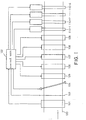
- Fig. 1 is a diagram illustrating a glass-plate sorting spister of this invention in which a glass-plate manufactur- inng Izme ranging from a discriminating-type flaw detector t a glass-plate sorting unit is shown.
- the manufacturing Izme mas a line conveyor 100 extending in the Y-axis direc- tzon, on which a glass strip pulled up from a furnace is transported
- a discriminating-type flaw detector 101 is a flying- s -pot discriminating-type flaw detector, as noted earlier, that scans the glass strip in the X-axis direction, normal to the Y-axis direction, with a light spot to detect flaws present in the glass strip and output flaw data representing the types, sizes (large-, medium- or small-size) and locations (X, Y) of the detected flaws.
- the flaw data thus produced are sent to a control unit 102 comprising a computer, for example.
- control unit 102 Upon receipt of the flaw data from the discriminating-type flaw detector 101, the control unit 102 identifies the sizes and locations of the flaws present in the glass strip, and initiates the tracking of the flaws.
- a trimming-line marker 103 marks a plurality of trimming lines in the Y-axis direction at predetermined intervals on the glass strip clearing the discriminating-type flaw detector 101.
- the trimming- line marker 103 is controlled by the control unit 102 to determine the x-axis locations of the trimming lines.
- a diagonal cutter 104 marks a plurality of cutting lines in the X-axis direction at predetermined intervals on the glass strip clearing the trimming-line marker 103.
- the diagonal cutter 104 has a cutter that travels in the diagonal direction in synchronism with the Y-axis speed of the glass strip. The travelling of the cutter and cutting-line settings are controlled by the control unit 102.
- a breaker 105 breaks, or cuts, the glass strip clearing the diagonal cutter 104 along the cutting lines into glass-plate rows.
- the breaker 105 is of a type that breaks the glass strip while moving up and down on the breaker roll under the control by the control unit 102.
- a trimming cutter 106 cuts and removes the trimmings along the trimming lines of the glass-plate rows broken by the breaker 105.
- the operation of the trimming cutter 106 too is controlled by the control unit 102.
- a slitter 107 slits the glass-plate rows along the trimming lines into a plurality of glass plates which are then slightly separated apart by small gaps in the X-axis direction.
- the slitter 107 too is controlled by the control unit 102.
- a separator 108 further separates the slit glass plates in the X-axis direction by the revolution of separating rolls to classify the plates by courses.
- the operation of the separator 108 too is controlled by the control unit 102.
- An eliminating/discarding unit 109 has such a construction that defective glass plates can be discarded by each course, based on the control by the control unit 102.
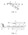
- Fig. 2 shows the construction of the eliminating/discarding unit for one course, in which as a defective glass plate 80 being discarded comes on a discarding roll 90, the defective plate 80 goes down on the discarding roll 90 for disposal in accordance with the control by the control unit 102.
- Fig. 3 shows the construction of one of the sorters viewed in the Y-axis direction.
- a line conveyor 100 provided is a suction conveyor 111 extending in the X-axis direction, while a lifter 112 is provided below the line conveyor 100.
- the lifter 112 pushes up the glass plate 113 travelling in the Y-axis direction on the line conveyor 100 based on the control by the control unit 102.
- the lifting operation by the lifter 112 is controlled in various modes, such as the selective lifting mode in which glass plates are lifted by selecting plates for courses; the collective lifting mode in which glass plates are lifted only when glass plates are lifted only when all the courses for one glass plate row can be lifted; and the course-wise lifting mode in which only those glass plates for a specified course are lifted.
- the glass plates 113 lifted are sucked by the suction conveyor 111 and transported in the X-axis direction to a transfer car 115 via a brush conveyor 114.
- Fig. 4 illustrates the sequence of the cutting and sorting operations of a glass strip travelling on the line conveyor 100.
- the detector 101 detects flaws existing in the glass strip 120, and transmits the flaw data representing the types, sizes and locations of the flaws to the control unit 102.
- the control unit 102 transmits the flaw data representing the types, sizes and locations of the flaws to the control unit 102.
- trimming-line maz ker 103 As the glass strip 120 arrives at the trimming-line maz ker 103, four trimming lines T 1 , T 2 , T 3 and T 4 are marked on the glass strip 120 in the Y-axis direction by the trimming-line marker 103.
- Fig. 4 shows a broken glass-plate row 121 between the cutting lines C 1 and C 2 . It is assumed that the glass-plate row 121 has the large-size flaw L and the medium-size flaw M, mentioned above.
- the trimming cutter 106 cuts and removes trimmings E 1 and E 2 , which are the edge parts of the glass-plate row 121, along the trimming lines T 1 and T 2 .
- the trimmed glass-plate row 121 is slit into three glass plates G 1 , G 2 and G 3 by the slitter 107, and the glass plates G 1 , G 2 and G 3 are slightly separated apart in the X-axis direction.
- the three glass plates thus slit G 1 , G and G 3 are further separated apart in the X-axis direction by the separator 108 to direct to the first, second and third courses.
- control unit 102 Since the control unit 102 keeps track of the locations of the flaws detected by the discriminating-type flaw detector 101 and controls the locations of the trimming lines marked by the trimming-line marker 103 and the cutting lines marked by diagonal cutter 104, the control unit 102 knows what sizes of the flaws exist at what locations in the glass plates separated apart by the separator 108. Thus, the control unit 102 identifies the glass plate having the medium-size flaw M as a high-grade-out, that is, a low-grade product, the glass plate having the large-size flaw L as a low-grade-out, that is, a defective plate being discarded, and the remaining as a high-grade product. In this way, the glass plates are sorted into high-grade, low-grade and defective products.
- the control unit 102 knows that the glass plate G 1 has the large-size flaw L, the glass plate G 2 has the medium-size flaw M, and the glass plate G 3 has no flaws, and therefore determines the glass plate G 3 as a high-grade product, the glass plate G 2 as a low-grade product, and the glass plate G 1 as a defective product. Based on the judgement, the control unit 102 controls the eliminating/discarding unit and the sorter.
- the control unit 102 lowers the discarding roll 90 for the first course, on which the defective plate G 1 travels, for removal from the line and disposal.
- the control unit 102 controls the sorters to sort the high-grade and the low-grade products.
- each sorter sorts high-grade or low-grade products for each course. That is, the sorter 110-1 sorts high-grade products for the first course, the sorter 110-2 sorts high-grade products for the second course, the sorter 110-3 sorts high-grade products for the third course, the sorter 110-4 sorts low-grade products for the first course, the sorter 110-5 sorts low-grade products for the second course, and the sorter 110-6 sorts low-grade products for the third course.
- the control unit 102 controls the lifter 112 of the sorter 110-3 to selectively lift the high-grade product G 3 .
- the control unit 102 controls the lifter 112 of the sorter to lift the low-grade product G 2 .
- the two-grade sorting process using the sorting system of this invention is capable of sorting high-grade and low-grade products simultaneously. Sorting the low-grade products that have heretofore been discarded in this way lead to increased yield in the manufacture of glass plates.
- the quality of glass plates from which automotive windshields are obtained is such that the glass plates need not be free of flaws over the entire surface thereof.
- the see-through area 2, which is critical in terms of driver's visibility, of a glass plate 1 shown in Fig. 5 must be free of flaws
- the peripheral area 3 around the see-through area 2 may have a certain degree of flaws.
- the fringe area 4, which is eventually discarded, may have any types of flaws.
- yield can be improved by sorting glass plates for windshields by detecting the sizes and locations of flaws in glass plates, and judging what size of flaws exist in the see-through area 2, peripheral area 3 and fringe area 4 assumed on the glass plate 1.
- Figs. 6A and 6B shows the cutting and sorting sequence of a glass strip on the line conveyor 100.
- the detector 101 detects a flaw existing in the glass strip 130, and transmits flaw data representing the types, sizes and locations of the flaws to the control unit 102. Now assume that there exist two small flaws S 1 and S 2 in the glass strip 130, as shown in the figure.
- trimming-line marker 103 As the glass strip 130 arrives at the trimming-line marker 103, three trimming lines T 1 , T and T 3 are marked in the Y-axis direction by the trimming-line marker 103.
- control unit 102 Since the control unit 102 keeps track of the locations of the flaws detected by the discriminating-type flaw detector 101 and controls the locations of the trimming lines marked by the trimming-line marker 103 and the cutting lines marked by the diagonal cutter 104, the control unit 102 knows what sizes of flaws exist at what locations in the glass plates separated apart by the separator 108. Furthermore, the control unit 102 assumes see-through, peripheral and fringe areas on the glass plate, sets quality grades for the see-through and peripheral areas to judge the acceptability of the glass plate in accordance with the quality grade settings.
- the control unit 102 assumes the see-through areas O 1 and O 2 , the peripheral areas P 1 and P 2 on the glass plate being cut, and knows that one small flaw S 1 is present in the peripheral area P 1 and the other small flaw S 2 is present in the see-through area 0 2 .
- the control unit 102 determines the glass plate being cut having the small flaw S 1 as a good product, and the glass plate being cut having the small flaw S 2 as a no-good product.
- the control unit also controls the eliminating/discarding unit and the sorter, base on the judgement.
- breaker 105 breaks the glass strip 130 into glass-plate rows along the cutting lines.
- Fig. 6A shows a broken glass-plate row 131 between the cutting lines C 1 and C 2 .
- the trimming cutter 106 cuts and removes trimmings E 1 and E 2 which are the edge parts of the glass-plate row 131 along the trimming lines T 1 and T 3 .
- the trimmed glass-plate row 131 is slit into two glass plates Gland G 2 by the slitter 107, and the glass plates Gland G 2 are slightly separated apart in the X-axis direction.
- the glass plate G 1 is a good product
- the glass plate G a no-good product.
- the two glass plates thus slit G 1 and G 2 are further separated apart in the X-axis direction by the separator 108 to direct to the first and second courses.
- the control unit 102 lowers the discarding roll for the second course, on which the defective plate G 2 travels, for removal from the line and disposal.
- control unit 102 controls the lifter of the sorter 110-1 to lift the good product G 1 and transport by the suction conveyor to the transfer car.
- the sorting process of automotive windshields using the sorting system of this invention makes it possible to sort as a good product the glass plate G 1 that has heretofore been discarded, leading to increased yield in the manufacture of automotive windshields.
- the glass-plate sorting system of this invention makes it possible to improve yield in the manufacture of glass plates by detecting the sizes and locations of flaws existing in a glass strip by means of a discriminating-type flaw detector of high precision, tracking the flaws by a control unit, and sorting quality grades of the glass plates being cut so as to simultaneously obtain a desired number of products of specified quality grades.
- the glass-plate sorting system of this invention makes it possible to improve yield in the manufacture of automotive windshields by detecting the sizes and locations -of flaws existing on a glass strip by a discriminating-type flaw detector of high precision, tracking the flaws by a control unit, and judging the acceptability of glass plates being cut by establishing criteria for quality grades in the see-through and peripheral areas of windshields on the glass plates being cut.
Abstract
Description
- This invention relates generally to a glass-plate sorting system for sorting glass plates on a glass-plate manufacturing line.
- The manufacture of glass plates generally involves the cutting and sorting glass plates out of a glass strip pulled up from the furnace while the glass strip travels on the line conveyor. In cutting glass plates out of the glass strip, a single-grade sorting system has heretofore been employed where only those glass plates which are above the aimed-at quality are sorted out, with the balance discarded.
- The conventional single-grade sorting/cutting system, however, has a disadvantage of poor yields in manufacturing products having strict quality requirements. Glass plates for automotive windshields, for example, are required to be free of flaws, and of a high quality from the viewpoint of safety. In the manufacturing process of glass plates for automotive windshields, therefore, they are inspected for the peresence/absence of flaws, and any glass plates in which flaws are found are discarded.
- Glass-plate products have a wide variety of applications ranging from glass plates for photocopying machines, which, require high quality, to glass panes for buildings, which: may be of lower quality. Consequently, producing glass plates by sorting high-grade products and low-grade ones simultaneously on the glass-plate manufacturing line would lead to glass-plate manufacture at the yield of the low-grade products.
- The quality of glass plates from which automotive windshields are obtained is such that a glass plate need not be free of flaws over the entire surface thereof, but only the see-through area thereof, which is critical for the vision of an automobile driver, must be free of flaws. The remaining peripheral areas immediately around the see-through area may have a certain degree of flaws, and the outermost fringe area of the plate, which are usually discarded, may have any types of flaws. In the manufacturing process of automotive windshields, therefore, glass-plate production yield can be improved by obtaining glass plates by detecting the sizes and locations of flaws in glass plates and judging what sizes of flaws would exist in the assumed see-through area, periphery area and fringe area of a glass plate .
- In order to implement the above-mentioned method for obtaining glass plates, a discriminating-type flaw detector is needed, which is capable of detecting at high accuracy the types, sizes, locations of flaws in a glass strip, such as bubbles formed by the air bubbles entrapped inside the glass plate, foreign particles remaining in the glass plate, knots formed by the almost molten foreign matter remaining in the glass plate in a shape having a streaming tail, drips formed by the metallic tin existing in the tin bath deposited on the glass plate surface. The present applicant has already developed a discriminating-type flaw detector meeting such a requirement and filed a patent application under the title of "A Discriminating-Type Flaw Detector For Light-Transmitting Plate Materials" on May 27, 1987 (Japanese Patent Application No. 62-128089). This discriminating-type flaw detector is a flying-spot type flaw detector that scans the entire surface of a glass plate with a light spot, detects transmitted light, transmitted and diffused light, reflected light, and reflected and diffused light by means of a plurality of light receptors, and discriminates the sizes and other parameters of flaws based on a combination of detected results.
- This invention is designed to improve yield by producing flaw data representing the types, sizes and locations of flaws, sending the data to the control unit of the gla.ss-plate sorting system to determine whether the glass plate can be cut in accordance with the quality requirements of the glass plate, using the discriminating-type flaw detector.
- Consequently, this invention is concerned with a glass-plate production system for cutting a glass strip travelling on a line conveyor into cut-lengths of glass plates and sorting the cut glass plates in accordance with required quality grades, which comprises a discriminating-type flaw detector that detects flaws on a glass strip and outputs the flaw data representing the sizes and locations of the flaws, a control unit for discriminating the quality grades of the cut glass plates, and a plurality of sorting units for sorting glass plates of desired quality grades.
- The use of the glass-plate sorting system of this invention makes it possible to obtain glass plates of two quality grades by sorting high-grade and low-grade plates. In doing so, the control unit of the glass-plate sorting system automatically discriminates glass plates being cut into high-grade, low-grade and defective ones, based on the flaw data transmitted from the discriminating-type flaw detector, to sort the high-garde and low-grade ones in the sorting unit and discard the defective ones by the eliminating/discarding unit. Thus, product yield can be improved by sorting, together with the high-grade products, the low-grade products that have heretofore been discarded in the conventional single-grade sorting system.
- When the glass-plate sorting system is used in the automotive windshield manufacturing line, product yield can be improved by tracking the flaws in a glass strip detected by the discriminating-type flaw detector, assuming see-through, peripheral and fringe areas of an automotive windshield on the glass plate cut out from the glass strip, and judging the acceptability of the glass plate based on the flaw existing in these areas.
-
- Fig. 1 is a diagram illustrating the construction of a glass-plate sorting system of this invention.
- Fig. 2 is a diagram illustrating a discarding roll.
- Fig. 3 is a diagram illustrating an example of the construction of a sorter.
- Fig. 4 is a diagram of assistance in explaining the operation required for sorting two grades of glass plates.
- Fig. 5 is a diagram illustrating the see-through, peripheral and fringe areas of an automotive windshield assumed on a glass plate from which an automotive windshield is obtained.
- F'igs. 6A and 6B are diagrams of assistance in explain- inng the operation required for sorting automotive wind- shzieldis.
- Fig. 1 is a diagram illustrating a glass-plate sorting spister of this invention in which a glass-plate manufactur- inng Izme ranging from a discriminating-type flaw detector t a glass-plate sorting unit is shown. The manufacturing Izme mas a
line conveyor 100 extending in the Y-axis direc- tzon, on which a glass strip pulled up from a furnace is transported - A discriminating-
type flaw detector 101 is a flying- s-pot discriminating-type flaw detector, as noted earlier, that scans the glass strip in the X-axis direction, normal to the Y-axis direction, with a light spot to detect flaws present in the glass strip and output flaw data representing the types, sizes (large-, medium- or small-size) and locations (X, Y) of the detected flaws. The flaw data thus produced are sent to acontrol unit 102 comprising a computer, for example. - Upon receipt of the flaw data from the discriminating-
type flaw detector 101, thecontrol unit 102 identifies the sizes and locations of the flaws present in the glass strip, and initiates the tracking of the flaws. - A trimming-
line marker 103 marks a plurality of trimming lines in the Y-axis direction at predetermined intervals on the glass strip clearing the discriminating-type flaw detector 101. The trimming-line marker 103 is controlled by thecontrol unit 102 to determine the x-axis locations of the trimming lines. - A
diagonal cutter 104 marks a plurality of cutting lines in the X-axis direction at predetermined intervals on the glass strip clearing the trimming-line marker 103. Thediagonal cutter 104 has a cutter that travels in the diagonal direction in synchronism with the Y-axis speed of the glass strip. The travelling of the cutter and cutting-line settings are controlled by thecontrol unit 102. - A
breaker 105 breaks, or cuts, the glass strip clearing thediagonal cutter 104 along the cutting lines into glass-plate rows. Thebreaker 105 is of a type that breaks the glass strip while moving up and down on the breaker roll under the control by thecontrol unit 102. - A trimming
cutter 106 cuts and removes the trimmings along the trimming lines of the glass-plate rows broken by thebreaker 105. The operation of thetrimming cutter 106 too is controlled by thecontrol unit 102. - A
slitter 107 slits the glass-plate rows along the trimming lines into a plurality of glass plates which are then slightly separated apart by small gaps in the X-axis direction. Theslitter 107 too is controlled by thecontrol unit 102. - A
separator 108 further separates the slit glass plates in the X-axis direction by the revolution of separating rolls to classify the plates by courses. The operation of theseparator 108 too is controlled by thecontrol unit 102. - An eliminating/discarding
unit 109 has such a construction that defective glass plates can be discarded by each course, based on the control by thecontrol unit 102. Fig. 2 shows the construction of the eliminating/discarding unit for one course, in which as adefective glass plate 80 being discarded comes on a discardingroll 90, thedefective plate 80 goes down on the discardingroll 90 for disposal in accordance with the control by thecontrol unit 102. - As indicated by numerals 110-1, 110-2, ---, and 110-6, six units of sorters are provided to sort glass plates based on the control by the
control unit 102. - Fig. 3 shows the construction of one of the sorters viewed in the Y-axis direction. Above a
line conveyor 100 provided is asuction conveyor 111 extending in the X-axis direction, while alifter 112 is provided below theline conveyor 100. Thelifter 112 pushes up theglass plate 113 travelling in the Y-axis direction on theline conveyor 100 based on the control by thecontrol unit 102. The lifting operation by thelifter 112 is controlled in various modes, such as the selective lifting mode in which glass plates are lifted by selecting plates for courses; the collective lifting mode in which glass plates are lifted only when glass plates are lifted only when all the courses for one glass plate row can be lifted; and the course-wise lifting mode in which only those glass plates for a specified course are lifted. Theglass plates 113 lifted are sucked by thesuction conveyor 111 and transported in the X-axis direction to atransfer car 115 via abrush conveyor 114. - Now, the two-grade sorting process to sort high-grade and low-grade plates using the glass-plate sorting system having the above-mentioned construction will be described in the sequence of the process, referring to Fig. 4. Fig. 4 illustrates the sequence of the cutting and sorting operations of a glass strip travelling on the
line conveyor 100. - When the glass strip ,120 pulled up from the furnace travels on the
line conveyor 100 to the discriminating-type flaw detector 101, thedetector 101 detects flaws existing in theglass strip 120, and transmits the flaw data representing the types, sizes and locations of the flaws to thecontrol unit 102. Now, assume that there exist a large-size flaw L and a medium-size flaw M in theglass strip 120, as shown in the figure. - As the
glass strip 120 arrives at the trimming-line maz ker 103, four trimming lines T1, T2, T3 and T4 are marked on theglass strip 120 in the Y-axis direction by the trimming-line marker 103. - Then, cutting lines C1, C2, C3, --- are successively marked in the X-axis direction by the
diagonal cutter 104. - As the
glass strip 120 marked with trimming and cut- timg lines arrives at thebreaker 105, thebreaker 105 breaks theglass strip 120 into glass-plate rows along the cuzting lines. Fig. 4 shows a broken glass-plate row 121 between the cutting lines C1 and C2. It is assumed that the glass-plate row 121 has the large-size flaw L and the medium-size flaw M, mentioned above. - The
trimming cutter 106 cuts and removes trimmings E1 and E2, which are the edge parts of the glass-plate row 121, along the trimming lines T1 and T2. - The trimmed glass-
plate row 121 is slit into three glass plates G1, G2 and G3 by theslitter 107, and the glass plates G1, G2 and G3 are slightly separated apart in the X-axis direction. - The three glass plates thus slit G1, G and G3 are further separated apart in the X-axis direction by the
separator 108 to direct to the first, second and third courses. - Since the
control unit 102 keeps track of the locations of the flaws detected by the discriminating-type flaw detector 101 and controls the locations of the trimming lines marked by the trimming-line marker 103 and the cutting lines marked bydiagonal cutter 104, thecontrol unit 102 knows what sizes of the flaws exist at what locations in the glass plates separated apart by theseparator 108. Thus, thecontrol unit 102 identifies the glass plate having the medium-size flaw M as a high-grade-out, that is, a low-grade product, the glass plate having the large-size flaw L as a low-grade-out, that is, a defective plate being discarded, and the remaining as a high-grade product. In this way, the glass plates are sorted into high-grade, low-grade and defective products. In doing so, thecontrol unit 102 knows that the glass plate G1 has the large-size flaw L, the glass plate G2 has the medium-size flaw M, and the glass plate G3 has no flaws, and therefore determines the glass plate G3 as a high-grade product, the glass plate G2 as a low-grade product, and the glass plate G1 as a defective product. Based on the judgement, thecontrol unit 102 controls the eliminating/discarding unit and the sorter. - As the glass plates G,, G2 and G3 arrive at the eliminating/discarding
unit 109, thecontrol unit 102 lowers the discardingroll 90 for the first course, on which the defective plate G1 travels, for removal from the line and disposal. - When the remaining low-grade product G2 and the high-grade product G3 on the second and third courses arrive at the sorting section having a plurality of sorters, the
control unit 102 controls the sorters to sort the high-grade and the low-grade products. Now, assume that each sorter sorts high-grade or low-grade products for each course. That is, the sorter 110-1 sorts high-grade products for the first course, the sorter 110-2 sorts high-grade products for the second course, the sorter 110-3 sorts high-grade products for the third course, the sorter 110-4 sorts low-grade products for the first course, the sorter 110-5 sorts low-grade products for the second course, and the sorter 110-6 sorts low-grade products for the third course. - As a high-grade product G3 on the third course arrives at the sorter 110-3, the
control unit 102 controls thelifter 112 of the sorter 110-3 to selectively lift the high-grade product G3. Similarly, as a low-grade product G2 on the second course arrives at the sorter 110-5, thecontrol unit 102 controls thelifter 112 of the sorter to lift the low-grade product G2. - As described above, the two-grade sorting process using the sorting system of this invention is capable of sorting high-grade and low-grade products simultaneously. Sorting the low-grade products that have heretofore been discarded in this way lead to increased yield in the manufacture of glass plates.
- Next, the sorting process of automotive windshields using the sorting system shown in Fig. 1 will be described in the following.
- As noted earlier, the quality of glass plates from which automotive windshields are obtained is such that the glass plates need not be free of flaws over the entire surface thereof. Although the see-through
area 2, which is critical in terms of driver's visibility, of aglass plate 1 shown in Fig. 5 must be free of flaws, theperipheral area 3 around the see-througharea 2 may have a certain degree of flaws. Moreover, thefringe area 4, which is eventually discarded, may have any types of flaws. - In the manufacture of automotive windshields, therefore, yield can be improved by sorting glass plates for windshields by detecting the sizes and locations of flaws in glass plates, and judging what size of flaws exist in the see-through
area 2,peripheral area 3 andfringe area 4 assumed on theglass plate 1. - Now, the sorting process, using the sorting system shown in Fig. 1, of glass plates for automotive windshields whose see-through area is of a high grade having no flaws, and whose peipherall area is of a low grade where small flaws are permitted will be described in the order of production sequence, referring to Figs. 6A and 6B. Figs. 6A and 6B shows the cutting and sorting sequence of a glass strip on the
line conveyor 100. - As a
glass strip 130 pulled up from the furnace travels on theline conveyor 100 to the discriminating-type flaw detector 101, thedetector 101 detects a flaw existing in theglass strip 130, and transmits flaw data representing the types, sizes and locations of the flaws to thecontrol unit 102. Now assume that there exist two small flaws S1 and S2 in theglass strip 130, as shown in the figure. - As the
glass strip 130 arrives at the trimming-line marker 103, three trimming lines T1, T and T3 are marked in the Y-axis direction by the trimming-line marker 103. - Then, cutting lines C1, C2, --- are successively marked by the
diagonal cutter 104. - Since the
control unit 102 keeps track of the locations of the flaws detected by the discriminating-type flaw detector 101 and controls the locations of the trimming lines marked by the trimming-line marker 103 and the cutting lines marked by thediagonal cutter 104, thecontrol unit 102 knows what sizes of flaws exist at what locations in the glass plates separated apart by theseparator 108. Furthermore, thecontrol unit 102 assumes see-through, peripheral and fringe areas on the glass plate, sets quality grades for the see-through and peripheral areas to judge the acceptability of the glass plate in accordance with the quality grade settings. In the process (c) shown in the figure, thecontrol unit 102 assumes the see-through areas O1 and O2, the peripheral areas P1 and P2 on the glass plate being cut, and knows that one small flaw S1 is present in the peripheral area P1 and the other small flaw S2 is present in the see-through area 02. Thus, thecontrol unit 102 determines the glass plate being cut having the small flaw S1 as a good product, and the glass plate being cut having the small flaw S2 as a no-good product. The control unit also controls the eliminating/discarding unit and the sorter, base on the judgement. - As the
glass strip 130 marked with trimming and cutting lines arrives at thebreaker 105, thebreaker 105 breaks theglass strip 130 into glass-plate rows along the cutting lines. Fig. 6A shows a broken glass-plate row 131 between the cutting lines C1 and C2. - The
trimming cutter 106 cuts and removes trimmings E1 and E2 which are the edge parts of the glass-plate row 131 along the trimming lines T1 and T3. - The trimmed glass-
plate row 131 is slit into two glass plates Gland G2 by theslitter 107, and the glass plates Gland G2 are slightly separated apart in the X-axis direction.
As is evident from the above description, the glass plate G1 is a good product, and the glass plate G a no-good product. - The two glass plates thus slit G1 and G2 are further separated apart in the X-axis direction by the
separator 108 to direct to the first and second courses. - As the glass plates G1 and G2 arrive at the eliminating/discarding
unit 109, thecontrol unit 102 lowers the discarding roll for the second course, on which the defective plate G2 travels, for removal from the line and disposal. - When the remaining low-grade product G1 on the first course arrives at the sorting section, the
control unit 102 controls the lifter of the sorter 110-1 to lift the good product G1 and transport by the suction conveyor to the transfer car. - As described above, the sorting process of automotive windshields using the sorting system of this invention makes it possible to sort as a good product the glass plate G1 that has heretofore been discarded, leading to increased yield in the manufacture of automotive windshields.
- Although the above description concerns with the sorting of glass plates for automotive windshields into those of a high grade having no flaws in the see-through area and those of a low grade that allows small flaws in the peripheral area, establishing the criteria for high- and low- grades depends on the quality requirements for specific automotive windshields.
- The glass-plate sorting system of this invention makes it possible to improve yield in the manufacture of glass plates by detecting the sizes and locations of flaws existing in a glass strip by means of a discriminating-type flaw detector of high precision, tracking the flaws by a control unit, and sorting quality grades of the glass plates being cut so as to simultaneously obtain a desired number of products of specified quality grades.
- When used in the manufacturing line of automotive windshields, the glass-plate sorting system of this invention makes it possible to improve yield in the manufacture of automotive windshields by detecting the sizes and locations -of flaws existing on a glass strip by a discriminating-type flaw detector of high precision, tracking the flaws by a control unit, and judging the acceptability of glass plates being cut by establishing criteria for quality grades in the see-through and peripheral areas of windshields on the glass plates being cut.
Claims (5)
Applications Claiming Priority (4)
| Application Number | Priority Date | Filing Date | Title |
|---|---|---|---|
| JP131523/87 | 1987-05-29 | ||
| JP131522/87 | 1987-05-29 | ||
| JP62131523A JPS63298037A (en) | 1987-05-29 | 1987-05-29 | Defect detecting and plate sampling method for windshield for automobile |
| JP62131522A JPS63298036A (en) | 1987-05-29 | 1987-05-29 | Two-grade plate sampling system |
Publications (3)
| Publication Number | Publication Date |
|---|---|
| EP0317638A1 true EP0317638A1 (en) | 1989-05-31 |
| EP0317638A4 EP0317638A4 (en) | 1989-10-12 |
| EP0317638B1 EP0317638B1 (en) | 1992-04-29 |
Family
ID=26466339
Family Applications (1)
| Application Number | Title | Priority Date | Filing Date |
|---|---|---|---|
| EP88904611A Expired - Lifetime EP0317638B1 (en) | 1987-05-29 | 1988-05-19 | Sorting system and method for glass sheets |
Country Status (4)
| Country | Link |
|---|---|
| US (1) | US5104523A (en) |
| EP (1) | EP0317638B1 (en) |
| DE (1) | DE3870584D1 (en) |
| WO (1) | WO1988009310A1 (en) |
Cited By (8)
| Publication number | Priority date | Publication date | Assignee | Title |
|---|---|---|---|---|
| EP0870582A1 (en) * | 1997-04-11 | 1998-10-14 | Elpatronic Ag | Method and apparatus for removing bad products from a sheet cutting machine |
| WO2000026647A1 (en) * | 1998-10-30 | 2000-05-11 | Image Processing Systems Inc. | Glass inspection system |
| WO2001081904A1 (en) * | 2000-04-20 | 2001-11-01 | Photon Dynamics Canada Inc. | Dark view inspection system for transparent media |
| US6501546B1 (en) | 2000-05-05 | 2002-12-31 | Photon Dynamics Canada Inc. | Inspection system for edges of glass |
| US6512239B1 (en) | 2000-06-27 | 2003-01-28 | Photon Dynamics Canada Inc. | Stereo vision inspection system for transparent media |
| ES2632211A1 (en) * | 2016-03-09 | 2017-09-11 | Hegla Gmbh & Co. Kg. | Procedure and device for the treatment of flat glass units in a glass processing installation (Machine-translation by Google Translate, not legally binding) |
| EP2622328B1 (en) | 2010-09-27 | 2019-08-07 | Viprotron GmbH | Method and device for indicating automatically identified flaws |
| CN114800660A (en) * | 2022-06-27 | 2022-07-29 | 浙江双元科技股份有限公司 | Defect positioning system and method for sheet slitting |
Families Citing this family (25)
| Publication number | Priority date | Publication date | Assignee | Title |
|---|---|---|---|---|
| JPH05249052A (en) * | 1992-03-06 | 1993-09-28 | Nippon Sheet Glass Co Ltd | Flaw detector for light-transmitting plate material |
| US6241244B1 (en) | 1997-11-28 | 2001-06-05 | Diebold, Incorporated | Document sensor for currency recycling automated banking machine |
| US7866185B2 (en) * | 2006-11-15 | 2011-01-11 | Corning Incorporated | Glass handling and processing system |
| DE102007043567B3 (en) * | 2007-09-13 | 2008-10-02 | Grenzebach Maschinenbau Gmbh | Method for removing a region of a glass strip continuously produced on a conveyor belt used during the production of float glass comprises scribing a line marking the removal of the glass strip |
| DE102007058786B3 (en) * | 2007-12-06 | 2009-01-29 | Grenzebach Maschinenbau Gmbh | Device and method for discharging glass plates in a production line and computer program and machine-readable carrier therefor |
| US8654333B2 (en) * | 2010-03-30 | 2014-02-18 | Fujifilm Corporation | Surface inspection apparatus and method |
| AT509963B1 (en) | 2010-06-07 | 2012-05-15 | Hermann Sonnleitner | DEVICE FOR PUNCTUALLY CLEANING AND INSPECTING ERRORS ON FLAT GLASS PANES |
| AT511055B1 (en) | 2011-03-24 | 2012-09-15 | Softsolution Gmbh | DEVICE FOR PROJECTION OF PRODUCT OR BZW. PRODUCTION RELEVANT PICTURE AND TEXT DATA AT PLANTS FOR THE PRODUCTION OF INDIVIDUAL OR BIN. INSULATING DISCS |
| EP2754524B1 (en) | 2013-01-15 | 2015-11-25 | Corning Laser Technologies GmbH | Method of and apparatus for laser based processing of flat substrates being wafer or glass element using a laser beam line |
| EP2781296B1 (en) | 2013-03-21 | 2020-10-21 | Corning Laser Technologies GmbH | Device and method for cutting out contours from flat substrates using a laser |
| US11556039B2 (en) | 2013-12-17 | 2023-01-17 | Corning Incorporated | Electrochromic coated glass articles and methods for laser processing the same |
| US10293436B2 (en) | 2013-12-17 | 2019-05-21 | Corning Incorporated | Method for rapid laser drilling of holes in glass and products made therefrom |
| DE102014107542B4 (en) | 2014-05-28 | 2020-02-06 | Softsolution Gmbh | Process for the manufacture of multi-pane flat glass products |
| KR102445217B1 (en) | 2014-07-08 | 2022-09-20 | 코닝 인코포레이티드 | Methods and apparatuses for laser processing materials |
| LT3169477T (en) | 2014-07-14 | 2020-05-25 | Corning Incorporated | System for and method of processing transparent materials using laser beam focal lines adjustable in length and diameter |
| FR3024137B1 (en) * | 2014-07-24 | 2016-07-29 | Saint Gobain | METHOD FOR MANUFACTURING COMPLEX SHAPE GLASS SHEETS |
| EP3848334A1 (en) | 2015-03-24 | 2021-07-14 | Corning Incorporated | Alkaline earth boro-aluminosilicate glass article with laser cut edge |
| WO2017011296A1 (en) | 2015-07-10 | 2017-01-19 | Corning Incorporated | Methods of continuous fabrication of holes in flexible substrate sheets and products relating to the same |
| CN109803786B (en) | 2016-09-30 | 2021-05-07 | 康宁股份有限公司 | Apparatus and method for laser processing of transparent workpieces using non-axisymmetric beam spots |
| US11542190B2 (en) | 2016-10-24 | 2023-01-03 | Corning Incorporated | Substrate processing station for laser-based machining of sheet-like glass substrates |
| US20180118602A1 (en) * | 2016-11-01 | 2018-05-03 | Corning Incorporated | Glass sheet transfer apparatuses for laser-based machining of sheet-like glass substrates |
| LT3615234T (en) * | 2017-04-28 | 2022-03-25 | Rockwool International A/S | A method and apparatus for rejection of defective mineral fibre slabs |
| CN108745956A (en) * | 2018-06-21 | 2018-11-06 | 广东拓斯达科技股份有限公司 | Glass dropping fraction location detecting apparatus and method, computer readable storage medium |
| CN112142311A (en) * | 2020-09-27 | 2020-12-29 | 山东奥大力自动化科技有限公司 | Glass cutting and breaking integrated machine conveyed through floating sucker |
| CN112974289B (en) * | 2020-11-09 | 2023-04-28 | 重庆康佳光电技术研究院有限公司 | Sorting method, sorting apparatus, computer-readable storage medium, and electronic device |
Family Cites Families (8)
| Publication number | Priority date | Publication date | Assignee | Title |
|---|---|---|---|---|
| US3246550A (en) * | 1959-11-02 | 1966-04-19 | Pittsburgh Plate Glass Co | Length and area partitioning methods and apparatus |
| US3215269A (en) * | 1961-01-27 | 1965-11-02 | Libbey Owens Ford Glass Co | Sheet handling apparatus |
| US3205740A (en) * | 1961-06-16 | 1965-09-14 | Pittsburgh Plate Glass Co | Glass partitioning apparatus |
| US3274390A (en) * | 1961-06-16 | 1966-09-20 | Pittsburgh Plate Glass Co | Glass cutting control apparatus |
| FR2279071A1 (en) * | 1974-07-19 | 1976-02-13 | Saint Gobain | INSTALLATION OF AUTOMATIC CONTROL OF THE CURVATURE OF BOMB WINDOWS |
| US4211132A (en) * | 1977-11-21 | 1980-07-08 | E. I. Du Pont De Nemours And Company | Apparatus for on-line defect zoning |
| WO1988009497A1 (en) * | 1987-05-27 | 1988-12-01 | Nippon Sheet Glass Co., Ltd. | Discriminative flaw detector for light-transmissive sheet material |
| JP3084415B2 (en) * | 1991-11-12 | 2000-09-04 | 三菱電機株式会社 | Video signal recording and playback device |
-
1988
- 1988-05-19 WO PCT/JP1988/000473 patent/WO1988009310A1/en active IP Right Grant
- 1988-05-19 DE DE8888904611T patent/DE3870584D1/en not_active Expired - Fee Related
- 1988-05-19 US US07/296,055 patent/US5104523A/en not_active Expired - Fee Related
- 1988-05-19 EP EP88904611A patent/EP0317638B1/en not_active Expired - Lifetime
Non-Patent Citations (1)
| Title |
|---|
| See references of WO8809310A1 * |
Cited By (10)
| Publication number | Priority date | Publication date | Assignee | Title |
|---|---|---|---|---|
| EP0870582A1 (en) * | 1997-04-11 | 1998-10-14 | Elpatronic Ag | Method and apparatus for removing bad products from a sheet cutting machine |
| WO2000026647A1 (en) * | 1998-10-30 | 2000-05-11 | Image Processing Systems Inc. | Glass inspection system |
| US6437357B1 (en) | 1998-10-30 | 2002-08-20 | Photon Dynamics Canada Inc. | Glass inspection system including bright field and dark field illumination |
| WO2001081904A1 (en) * | 2000-04-20 | 2001-11-01 | Photon Dynamics Canada Inc. | Dark view inspection system for transparent media |
| US6633377B1 (en) | 2000-04-20 | 2003-10-14 | Image Processing Systems Inc. | Dark view inspection system for transparent media |
| US6501546B1 (en) | 2000-05-05 | 2002-12-31 | Photon Dynamics Canada Inc. | Inspection system for edges of glass |
| US6512239B1 (en) | 2000-06-27 | 2003-01-28 | Photon Dynamics Canada Inc. | Stereo vision inspection system for transparent media |
| EP2622328B1 (en) | 2010-09-27 | 2019-08-07 | Viprotron GmbH | Method and device for indicating automatically identified flaws |
| ES2632211A1 (en) * | 2016-03-09 | 2017-09-11 | Hegla Gmbh & Co. Kg. | Procedure and device for the treatment of flat glass units in a glass processing installation (Machine-translation by Google Translate, not legally binding) |
| CN114800660A (en) * | 2022-06-27 | 2022-07-29 | 浙江双元科技股份有限公司 | Defect positioning system and method for sheet slitting |
Also Published As
| Publication number | Publication date |
|---|---|
| EP0317638B1 (en) | 1992-04-29 |
| US5104523A (en) | 1992-04-14 |
| WO1988009310A1 (en) | 1988-12-01 |
| DE3870584D1 (en) | 1992-06-04 |
| EP0317638A4 (en) | 1989-10-12 |
Similar Documents
| Publication | Publication Date | Title |
|---|---|---|
| EP0317638A1 (en) | Sorting system and method for glass sheets | |
| US5115144A (en) | Automatic selection apparatus of sheet material | |
| CN113182203B (en) | Intelligent silkworm cocoon sorting method | |
| US20220017401A1 (en) | Device and method for length cutting in ultrathin glasses | |
| CN110655313A (en) | Method and equipment for optimally cutting float glass | |
| CN1139476C (en) | Method and device for producing hollow bodies | |
| JP3739333B2 (en) | Sheet glass cleaving system | |
| CN114733795A (en) | Crushed material detecting and removing device, detecting and removing method and sorting system | |
| CN110823912A (en) | Ceramic ring coating defect detection system and detection method based on machine vision | |
| US3190518A (en) | Apparatus for cutting, transporting and distributing glass sheets | |
| CN220479470U (en) | Stone grading device | |
| KR950006196B1 (en) | Pick-up system of glass sheets | |
| CN116274007A (en) | Double-magazine receiving device and discharging and sorting equipment | |
| CN210585945U (en) | Copper-clad plate detecting and sorting system | |
| EP0587542B1 (en) | Method and apparatus for cutting a large glass sheet into smaller sizes | |
| JPS63298036A (en) | Two-grade plate sampling system | |
| JP7424302B2 (en) | Glass plate manufacturing method and manufacturing equipment | |
| JPS63298037A (en) | Defect detecting and plate sampling method for windshield for automobile | |
| CA2235665A1 (en) | Method for sorting wastepaper | |
| CN220901059U (en) | Glass defective product cutting processing production line | |
| CN211160774U (en) | Glass grading and collecting system | |
| JP7424303B2 (en) | Glass plate manufacturing method and manufacturing device | |
| CN113837528B (en) | Method for determining position of station causing defect on surface of substrate glass | |
| JP3700864B2 (en) | Glass tube sorting equipment | |
| CA3136766C (en) | Computer-assisted shingle sawing method and installation |
Legal Events
| Date | Code | Title | Description |
|---|---|---|---|
| PUAI | Public reference made under article 153(3) epc to a published international application that has entered the european phase |
Free format text: ORIGINAL CODE: 0009012 |
|
| AK | Designated contracting states |
Kind code of ref document: A1 Designated state(s): DE FR GB |
|
| 17P | Request for examination filed |
Effective date: 19890502 |
|
| A4 | Supplementary search report drawn up and despatched |
Effective date: 19891012 |
|
| 17Q | First examination report despatched |
Effective date: 19910613 |
|
| RAP1 | Party data changed (applicant data changed or rights of an application transferred) |
Owner name: NIPPON SHEET GLASS CO., LTD. |
|
| GRAA | (expected) grant |
Free format text: ORIGINAL CODE: 0009210 |
|
| AK | Designated contracting states |
Kind code of ref document: B1 Designated state(s): DE FR GB |
|
| REF | Corresponds to: |
Ref document number: 3870584 Country of ref document: DE Date of ref document: 19920604 |
|
| ET | Fr: translation filed | ||
| PLBE | No opposition filed within time limit |
Free format text: ORIGINAL CODE: 0009261 |
|
| STAA | Information on the status of an ep patent application or granted ep patent |
Free format text: STATUS: NO OPPOSITION FILED WITHIN TIME LIMIT |
|
| 26N | No opposition filed | ||
| REG | Reference to a national code |
Ref country code: GB Ref legal event code: IF02 |
|
| PGFP | Annual fee paid to national office [announced via postgrant information from national office to epo] |
Ref country code: FR Payment date: 20020508 Year of fee payment: 15 |
|
| PGFP | Annual fee paid to national office [announced via postgrant information from national office to epo] |
Ref country code: GB Payment date: 20020515 Year of fee payment: 15 |
|
| PGFP | Annual fee paid to national office [announced via postgrant information from national office to epo] |
Ref country code: DE Payment date: 20020522 Year of fee payment: 15 |
|
| PG25 | Lapsed in a contracting state [announced via postgrant information from national office to epo] |
Ref country code: GB Free format text: LAPSE BECAUSE OF NON-PAYMENT OF DUE FEES Effective date: 20030519 |
|
| PG25 | Lapsed in a contracting state [announced via postgrant information from national office to epo] |
Ref country code: DE Free format text: LAPSE BECAUSE OF NON-PAYMENT OF DUE FEES Effective date: 20031202 |
|
| GBPC | Gb: european patent ceased through non-payment of renewal fee |
Effective date: 20030519 |
|
| PG25 | Lapsed in a contracting state [announced via postgrant information from national office to epo] |
Ref country code: FR Free format text: LAPSE BECAUSE OF NON-PAYMENT OF DUE FEES Effective date: 20040130 |
|
| REG | Reference to a national code |
Ref country code: FR Ref legal event code: ST |