EP0316985B1 - Verfahren zum Steuern eines Bohrvorganges durch Analysierung des zirkulierenden Bohrschlammes - Google Patents
Verfahren zum Steuern eines Bohrvorganges durch Analysierung des zirkulierenden Bohrschlammes Download PDFInfo
- Publication number
- EP0316985B1 EP0316985B1 EP88202433A EP88202433A EP0316985B1 EP 0316985 B1 EP0316985 B1 EP 0316985B1 EP 88202433 A EP88202433 A EP 88202433A EP 88202433 A EP88202433 A EP 88202433A EP 0316985 B1 EP0316985 B1 EP 0316985B1
- Authority
- EP
- European Patent Office
- Prior art keywords
- mud
- weight
- solids
- series
- values
- Prior art date
- Legal status (The legal status is an assumption and is not a legal conclusion. Google has not performed a legal analysis and makes no representation as to the accuracy of the status listed.)
- Expired - Lifetime
Links
Images

Classifications
-
- E—FIXED CONSTRUCTIONS
- E21—EARTH OR ROCK DRILLING; MINING
- E21B—EARTH OR ROCK DRILLING; OBTAINING OIL, GAS, WATER, SOLUBLE OR MELTABLE MATERIALS OR A SLURRY OF MINERALS FROM WELLS
- E21B44/00—Automatic control systems specially adapted for drilling operations, i.e. self-operating systems which function to carry out or modify a drilling operation without intervention of a human operator, e.g. computer-controlled drilling systems; Systems specially adapted for monitoring a plurality of drilling variables or conditions
-
- E—FIXED CONSTRUCTIONS
- E21—EARTH OR ROCK DRILLING; MINING
- E21B—EARTH OR ROCK DRILLING; OBTAINING OIL, GAS, WATER, SOLUBLE OR MELTABLE MATERIALS OR A SLURRY OF MINERALS FROM WELLS
- E21B21/00—Methods or apparatus for flushing boreholes, e.g. by use of exhaust air from motor
- E21B21/08—Controlling or monitoring pressure or flow of drilling fluid, e.g. automatic filling of boreholes, automatic control of bottom pressure
-
- E—FIXED CONSTRUCTIONS
- E21—EARTH OR ROCK DRILLING; MINING
- E21B—EARTH OR ROCK DRILLING; OBTAINING OIL, GAS, WATER, SOLUBLE OR MELTABLE MATERIALS OR A SLURRY OF MINERALS FROM WELLS
- E21B49/00—Testing the nature of borehole walls; Formation testing; Methods or apparatus for obtaining samples of soil or well fluids, specially adapted to earth drilling or wells
- E21B49/005—Testing the nature of borehole walls or the formation by using drilling mud or cutting data
-
- G—PHYSICS
- G01—MEASURING; TESTING
- G01N—INVESTIGATING OR ANALYSING MATERIALS BY DETERMINING THEIR CHEMICAL OR PHYSICAL PROPERTIES
- G01N30/00—Investigating or analysing materials by separation into components using adsorption, absorption or similar phenomena or using ion-exchange, e.g. chromatography or field flow fractionation
- G01N30/02—Column chromatography
Definitions
- This invention relates to a method of monitoring the drilling operations and more particularly, the drilling fluid, called drilling mud, to identify changes in the drilling process by monitoring continuously a parameter representative of the weight of fine solids present in the mud.
- a mud In the rotary drilling of wells, such as hydrocarbon wells, a mud is continuously circulated from the surface down to the bottom of the hole being drilled and back to the surface again.
- the mud has several functions, one of them being to transport the cuttings drilled by the drill bit up to the surface where they are separated from the mud. Another function is to impose an hydrostatic pressure on the walls of the borehole so as to avoid a collapse of the borehole and a surge of gas or liquid present into the formations being drilled.
- the characteristics of the mud are therefore important to monitor and to keep within certain limits. For example, the density must be large enough so as to exert a certain hydrostatic pressure on the formations but not too large to fracture these formations.
- the viscosity of the mud is also an important characteristic since it contributes to the cutting transport capability of the mud.
- Weighting materials barite for example, are added to the mud to make it exert as much pressure as needed to contain the formation pressures.
- Clay is added to the mud so as to keep the bit cuttings in suspension as they move up the hole. The clay also sheathes the wall of the hole. This thin layer of clay, called wall cake, makes the hole stable so it will not cave in or slough. Numerous chemicals are available to give the mud the exact properties it needs to make it as easy as possible to drill the hole.
- Maintaining the stability of the borehole is one of the major problems encountered in drilling oil and gas wells. Hole instability is evidenced by the squeezing the soft, ductile formations into the borehole, the excavation under stress of hard, brittle formations and the caving of shales with consequent hole enlargement. These problems increase drilling time and thus cost and may result in stuck drill pipe.
- the various forms of hole instability resulting from the interaction between the drilling fluid and the subterranean formations penetrated by the borehole are related to the hydration and dispersion of the clay sediments.
- the current practice on the drilling rigs is to make a number of measurements on the mud system, usually at a rate of one per day, the main object of which is to monitor the efficiency of the solids control equipment in removing fine drilled solids from the mud.
- These measurements are not interpreted in terms of lithology or mud-formation interactions, but are used for maintaining the solids content of the mud within certain bounds for the purposes of controlling rheology, mud weight, quality of filter cake and drilling rate.
- the emphasis of the measurements is therefore to keep the mud to some specification of performance.
- GB 1,280,227 discloses means for monitoring properties of drilling mud, including the density of the mud, after cuttings removal.
- the system described includes a holding loop around which mud is circulated after cuttings removal and from which samples may be taken periodically for analysis.
- the present invention is directed to a method of monitoring the drilling operations by analysing the circulating drilling mud. Samples of mud are taken periodically at the surface at one or several locations where the mud does not contain cuttings anymore. The mud samples are analysed on the rig site to determine the successive values, as a function of time or depth, of the weight of the fine solids present in the mud.
- the weight of the liquid phase is determined by drying to constant weight a given weight of mud and the weight of electrolyte is determined by chemical analysis of the mud filtrate using an ion chromatography system on the rig site.
- the fractional weight solids content of the mud is determined for each sample.
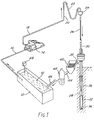
- the mud 10 is contained in a mud pit 12, called the active tank.
- a pump 14 draws up the mud from the pit though a pipe 16 and forces the mud through the discharge line 18, the stand pipe 20, the rotary hose 22 and the swivel 24.
- the mud then flows into the kelly 26 and down the borehole 28 in the drill pipe 30 and the drill collars 32.
- the mud reaches the bottom of the hole at the drill bit 34 and then flows up to the surface in the annulus 36 and in the mud return line 38.
- the mud then falls over a vibrating screen-like device 40, called a shale shaker.
- the role of the shale shaker is to separate from the liquid phase of the mud, the cuttings drilled by the bit 34 and transported up in the annulus by the mud.
- the separation is made by having the mud passing through a screen which vibrates.
- the solids which are larger than the mesh size of the screen don't pass through the screen and are rejected either in a reserve pit when the drilling rig is on land or in a barge when the drilling operations are conducted offshore.
- the solid particles contained in the mud which have a size smaller than the mesh size of the screen pass through the screen and therefore remain in the mud.
- These fine solids comprise part of the weighting material added to the mud to reach a certain mud density and also fine solids from the formations traversed by the borehole.
- the solid control equipment 42 could include a degasser, a desilter and a desander. Then the mid falls into the pit 10 through the pipe 46.
- a mud-mixing hopper 48 is generally used to add solid materials like clay and barite to the mud in the active tank.
- the following description of the invention refers to experiments which have been made with mud samples taken from both the active tank 12 and from the pipe 44 between the shale shaker 40 and the solids control equipment 42. For each sample, the weight percent solids content of the mud was measured. The measurements were used to give the quantitative determination of solids removal by the solids control equipment, the effect of mud dilution operations, the build-up of fine drilled solids and the correlation of solids content to the drilled lithology.
- the fractional weight solids content w of mud is defined by where M s is the weight of solid in a weight M m of mud.
- M e of electrolyte in the aqueous phase of the mud is due to the total dissolved solids (TDS).
- TDS total dissolved solids
- the determination of w involves measurement of the weight M w and M l of liquid and electrolyte in a weight M m of mud.
- a given weight of mud is dried to constant weight using drying apparatus such as a small oven or an infra-red drying balance.
- the weight loss on drying is the weight of liquid M l .
- the drying temperature must be at least 105°C to ensure that the water in the mud solution phase is removed.
- the weight of the dried solids contains a weight M e of solid electrolyte which must be subtracted.
- the weight of electrolyte M e in the liquid phase is given by where TDS is the total weight of electrolyte in the mud in grams per liter and d l is the density of the liquid (in g.cm -3 ).
- concentration c i of ion i is determined by the chemical analysis of the mud filtrate at the rig site, preferably using an ion chromatography system such as described in our copending UK patent application no 8705502.
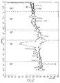
- Fig 2 shows the variation of the weight percent solids content (ie,w x 100) of a suite of field mud samples.
- the mud was sampled in two different locations: the round points 50 correspond to samples taken from the active tank 12, while the triangle-shape points 52 correspond to samples taken immediately below the shaker 40 in the return mud pipe 44, before the solids control equipment 42.
- Superimposed on Fig 2 is the drilled lithology converted to sample time t (in hours) from a knowledge of the drilled depth as a function of time and the annulus lag time (calculated to be in the range 50-60 minutes over this drilled section).
- the five formations are marl 54, limestone 56 and three distinct shale units 58, 60, and 62.
- the horizontal dotted lines represent the formation boundaries.
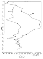
- Fig 3 shows the dependence of the total dissolved solids (TDS), in g/l, of the mud samples on the sample time t (in hours).
- the TDS data shown in fig 3 have a rounded shape 64 for the samples taken from the active tank 12 and a triangle shape 66 for the samples taken between the shale shaker and the solids control equipment 42. These data were used in equations [3] and [5] to calculate w.
- the mud samples on which the TDS was measured account for only about a quarter of the number shown in fig 2; the value of TDS for the remaining samples was obtained by interpolation.
- the TDS is generally larger in the active tank samples and therefore failure to correct for M e leads to greater error in the active tank solids content than in the return mud samples.
- TDS values for the active tank samples compared with the return line samples are due to solids added in the mud in the tank, such as sodium hydroxide, which were not homogeneously dispersed in the tank and their concentration was larger at the location the samples were taken. This suggests that it is probably more appropriate to sample the mud at a location between the discharge line 18 and the kelly 26.
- Fig 4 shows a comparison of w with the uncorrected value w' where the effect of M e has been ignored, ie, The maximum difference between w and w' is 4.2 weight percent while the average difference is 3.5 weight percent.
- the solids removal by the solids control equipment is determined.
- the return and active mud sampling points are separated by the solids control equipment 42.
- the time lag between the two sampling points is V A /Q where V A is the volume of mud in the active tank and Q is the mud flow rate.
- V A is approximately 6365 litres and the average flow rate Q is 3090 l/min, and thus the surface time lag is about 20 minutes.
- the solids content of the active tank mud samples is a constant 0.5% lower than that in the return mud samples.
- the reduction in w on passing through the solids control equipment is therefore 0.5% which represents a removal of only 2% of the total solids content.
- the rate of removal of solids from the mud is given by where ⁇ w is the decrease in solids content and d m is the mud density.
- ⁇ w 0.005
- d m 1180 kgm -3
- Q 154 m 3 /hr (3090 l/min)
- the rate of solids removal is about 900 kg/hr.
- the largely constant separation between the active tank and the return mud solids content logs means that the rate of increase of w in the return mud is equal to that of the mud in the active tank.
- any item of solids control equipment eg, centrifuge
- the contribution of any item of solids control equipment to the removal of solids from the mud system can be measured by taking samples from the mud stream before and after the equipment.
- the 0.5 weight percent solids removal by the solids control equipment in this particular well can then be broken down into removal by each component of the equipment.
- the usual method of combatting the build-up of solids in the mud system is dilution or mud discharge followed by mud replacement.
- the rather regular pattern of spikes in the active tank solids log following the dilution is the result of intermittent addition of seawater.
- the solids content is back to the pre-dilution value.
- a correlation between the mud solids content and the drilled lithology is made.
- the description of solids removal in the preceding section emphasised the comparison between the return and active tank mud samples at the surface where the difference between the solids content is largely a result of solids removal by the solids control equipment.
- the other comparison which can be made is between the active tank and retern mud samples (or generally speaking between the mud flowing in the borehole and the mud flowing out of the borehole), where the difference is due to the mud retaining drilled solids which are not removed by the shale shaker, ie, fine solids.
- the occurrence of fine drilled solids in the mud, as measured by an increase in w, is related to lithology, particularly to dispersing shales which are usually characterised by a high montmorillonite content.
- the invention is therefore a powerful method for monitoring the stability of the borehole. For example, if the formation being drilled is highly dispersive, the cuttings will dissolve, at least partly, into the mud and this will increase the value of w.
- the return mud solids content log (fig 2) contains six sharp increases in w of which at least five can be related to the accurately known drilled lithology.
- the conductivity of the thin bed is about 2000 mS/m compared to an almost constant value of 300 mS/m for the limestone.
- This thin bed is a characteristic of the whole field and is used as a marker in each well.
- the increase in w is due to the almost complete dispersion of cuttings from the thin bed, which is probably a thin bentonite stringer.
- This thin bed is also likely to be a stringer of a high montmorillonite content shale.
- the second shale is known to contain about 45% montmorillonite and in previous wells gave rise to considerable wellbore stability problems.
- the electrical conductivity of the thin bed rises from a uniform value of 400 mS/m in the surrounding shale to 1000 mS/m.
- the gamma ray log shows a sharp spike at this point.
- the last thin bed is the only feature in this drilled section to show any sudden change in the gamma ray log; the thin bed probably corresponds to an organic-rich high montmorillonite content shale stringer.
- the spikes in the return mud solids content log can be correlated with the thin highly conducting beds found by wireline logs.
- the sample time at which the peak occurs can be converted into drilled depth by a knowledge of the drilled depth as a function of time and the annulus lag time.
- the estimated depth of the thin beds from the solids contents log is within 5 meters of the depth found from wireline logs.
Landscapes
- Engineering & Computer Science (AREA)
- Geology (AREA)
- Life Sciences & Earth Sciences (AREA)
- Mining & Mineral Resources (AREA)
- Environmental & Geological Engineering (AREA)
- Fluid Mechanics (AREA)
- Physics & Mathematics (AREA)
- General Life Sciences & Earth Sciences (AREA)
- Geochemistry & Mineralogy (AREA)
- Mechanical Engineering (AREA)
- Sampling And Sample Adjustment (AREA)
- Treatment Of Sludge (AREA)
- Bulkheads Adapted To Foundation Construction (AREA)
Claims (8)
- Verfahren zum Überwachen von Bohroperationen, umfassend das Analysieren von zirkulierendem Bohrschlamm durch periodisches Nehmen von Schlammproben an der Oberfläche nach der Entfernung von Bohrabfall sowie Analysieren der Proben, um die aufeinanderfolgenden Werte des Gewichts Ms im Schlamm vorhandener feiner Festkörper in Abhängigkeit von der Zeit oder der Tiefe zu bestimmen, dadurch gekennzeichnet, daß das Gewicht M1 der flüssigen Phase durch Trocknen eines gegebenen Gewichts Mm des Schlamms auf ein konstantes Gewicht bestimmt wird und daß das Gewicht Me des Elektrolyten bestimmt wird, der in der in einem bekannten Gewicht Mm von Schlamm vorhandenen flüssigen Phase gelöst ist, wobei das Gewicht Ms der feinen Festkörper in der Probe bestimmt wird durch den Ausdruck:
- Verfahren nach Anspruch 1, gekennzeichnet durch das Bestimmen des Verhältnisses Ms/Mm für jede Probe, das den Gewichtsanteil w enthaltener Festkörper darstellt.
- Verfahren nach Anspruch 1 oder 2, gekennzeichnet durch Bestimmen des Gewichts Me des Elektrolyten durch chemische Analyse eines Schlammfiltrats unter Verwendung eines lonenchromatographie-Systems.
- Verfahren nach irgendeinem der vorangehenden Ansprüche, gekennzeichnet durch das Nehmen von Proben des in einem Bohrschacht strömenden Bohrschlamms und Beobachten der Entwicklung der aufeinanderfolgenden Werte des Gewichts feiner Festkörper, um so die Verdünnung des Schlamms zu überwachen.
- Verfahren nach irgendeinem der vorangehenden Ansprüche, gekennzeichnet durch das Nehmen von Proben des Bohrschlamms, der in das Bohrloch hinein- oder aus diesem herausströmt und aus dem Bohrabfälle entfernt worden sind, an zwei getrennten Stellen, Bestimmen der aufeinanderfolgenden Werte des Gewichts der im Schlamm enthaltenen Festkörper in Abhängigkeit von der Zeit oder der Tiefe, um so zwei Reihen von Werten zu erhalten, die auf den in das Bohrloch und aus dem Bohrloch strömenden Schlamm bezogen sind, und Vergleichen der beiden Reihen von Werten.
- Verfahren nach Anspruch 5, gekennzeichnet durch das Bestimmen der Zeitverzögerung des Schlamms, um sich von der einen der Stellen zur anderen zu bewegen, Verschieben einer der Reihen von Werten in bezug auf die andere um die Zeitverzögerung oder um die entsprechenden Tiefendifferenzen und Vergleichen der beiden Reihen von Werten.
- Verfahren nach Anspruch 5 oder 6, gekennzeichnet durch das Vergleichen der Reihen von Werten, die den direkt nach der Entfernung der Bohrabfälle genommenen Proben entsprechen, mit den Reihen von Werten, die den nach der Festkörperkontrolle genommenen Proben entsprechen, um so den Wirkungsgrad der Festkörperkontrollanordnung, die die Abfallentfernungseinrichtung nicht enthält, zu bestimmen.
- Verfahren nach Anspruch 5 oder 6, gekennzeichnet durch das Vergleichen der Reihen von Werten, die dem in den Bohrschacht gelangenden Schlamm entsprechen, mit den Reihen von Werten, die dem vom Bohrschacht zurückkehrenden Schlamm entsprechen, um so das Vergleichsergebnis mit der gebohrten Lithologie zu korrelieren.
Applications Claiming Priority (2)
| Application Number | Priority Date | Filing Date | Title |
|---|---|---|---|
| GB8726727 | 1987-11-14 | ||
| GB8726727A GB2212611B (en) | 1987-11-14 | 1987-11-14 | A method of monitoring the drilling operations by analysing the circulating drilling mud |
Publications (2)
| Publication Number | Publication Date |
|---|---|
| EP0316985A1 EP0316985A1 (de) | 1989-05-24 |
| EP0316985B1 true EP0316985B1 (de) | 2000-01-19 |
Family
ID=10626988
Family Applications (1)
| Application Number | Title | Priority Date | Filing Date |
|---|---|---|---|
| EP88202433A Expired - Lifetime EP0316985B1 (de) | 1987-11-14 | 1988-11-01 | Verfahren zum Steuern eines Bohrvorganges durch Analysierung des zirkulierenden Bohrschlammes |
Country Status (5)
| Country | Link |
|---|---|
| US (1) | US4878382A (de) |
| EP (1) | EP0316985B1 (de) |
| DE (1) | DE3856393T2 (de) |
| GB (1) | GB2212611B (de) |
| NO (1) | NO885033L (de) |
Cited By (2)
| Publication number | Priority date | Publication date | Assignee | Title |
|---|---|---|---|---|
| WO2015050563A1 (en) * | 2013-10-04 | 2015-04-09 | Landmark Graphics Corporation | Dynamic method and real time monitoring of ubd operation tunnel envelope with mud motor |
| US9222350B2 (en) | 2011-06-21 | 2015-12-29 | Diamond Innovations, Inc. | Cutter tool insert having sensing device |
Families Citing this family (30)
| Publication number | Priority date | Publication date | Assignee | Title |
|---|---|---|---|---|
| GB2226135A (en) * | 1988-12-15 | 1990-06-20 | Forex Neptune Sa | Monitoring ions present in drilling muds or fluids |
| US4979393A (en) * | 1989-08-24 | 1990-12-25 | Exxon Production Research Company | Process for rapidly determining the solids content in drilling fluids |
| GB2237305B (en) * | 1989-10-28 | 1993-03-31 | Schlumberger Prospection | Analysis of drilling solids samples |
| GB2237303A (en) * | 1989-10-28 | 1991-05-01 | Services Tech Sedco Forex | Method of quantitative analysis of drilling fluid products |
| GB8926778D0 (en) * | 1989-11-27 | 1990-01-17 | Forex Neptune Serv Tech Sa | Sampling of drilling mud |
| GB9107041D0 (en) * | 1991-04-04 | 1991-05-22 | Schlumberger Services Petrol | Analysis of drilling fluids |
| GB2284887B (en) * | 1993-12-17 | 1997-12-10 | Pumptech Nv | Method of analysing drilling fluids |
| US5641895A (en) * | 1995-05-01 | 1997-06-24 | Fsi International, Inc. | Dynamic contaminant extraction measurement for chemical distribution systems |
| US5627076A (en) * | 1995-11-13 | 1997-05-06 | Baker Hughes Incorporated | Method for determination of glycols and polyglycols in drilling fluid filtrates |
| CA2256258C (en) * | 1998-12-16 | 2007-10-02 | Konstandinos S. Zamfes | Swab test for determining relative formation productivity |
| US6386026B1 (en) * | 2000-11-13 | 2002-05-14 | Konstandinos S. Zamfes | Cuttings sample catcher and method of use |
| US20020112888A1 (en) * | 2000-12-18 | 2002-08-22 | Christian Leuchtenberg | Drilling system and method |
| US7150183B2 (en) * | 2003-06-19 | 2006-12-19 | Schlumberger Technology Corporation | Compositional characterization and quantification of solid deposits from hydrocarbon fluids |
| US20060011547A1 (en) * | 2004-07-13 | 2006-01-19 | Bell Stephen A | Methods of separating components in treatment fluids |
| FR2875712B1 (fr) * | 2004-09-30 | 2006-12-01 | Geoservices | Dispositif d'extraction d'au moins un gaz contenu dans une boue de forage et ensemble d'analyse associe |
| NO322618B1 (no) * | 2005-04-20 | 2006-11-06 | 2K Tech As | Anordning og fremgangsmate for tilstandskontroll. |
| US7846135B2 (en) * | 2006-02-24 | 2010-12-07 | Midland Medical Holding LLC | Retractable needle syringe with needle trap |
| CN101951980A (zh) * | 2007-03-21 | 2011-01-19 | 米德兰医疗设备控股有限公司 | 具有能缩进的针并包括接纳在套筒内的柱塞的安全医疗注射器 |
| AR070613A1 (es) * | 2008-02-18 | 2010-04-21 | Mi Llc | Procedimiento de prueba para determinar la concentracion y distribucion relativa de particulas dimensionadas en un fluido de perforacion |
| GB201019912D0 (en) * | 2010-11-24 | 2011-01-05 | Caledus Ltd | Drill pipe tubing and casing protector |
| US8775086B2 (en) | 2011-03-30 | 2014-07-08 | Weatherford/Lamb, Inc. | Lag calculation with caving correction in open hole |
| US8965703B2 (en) | 2011-10-03 | 2015-02-24 | Schlumberger Technology Corporation | Applications based on fluid properties measured downhole |
| CN103389252B (zh) * | 2013-07-04 | 2015-11-11 | 北京仁创科技集团有限公司 | 支撑剂流速对管道冲蚀影响的测定装置 |
| US10151160B2 (en) | 2016-05-13 | 2018-12-11 | Cameron International Corporation | Drilling fluid measurement system |
| RU2652908C2 (ru) * | 2016-07-04 | 2018-05-03 | Артем Юрьевич Верзаков | Буровая установка |
| RU2679424C1 (ru) * | 2018-02-17 | 2019-02-08 | Александр Васильевич Селиванов | Буровая установка горизонтального бурения |
| US10385635B1 (en) * | 2018-06-05 | 2019-08-20 | Southpaw Fabrication | Diffuser and solids collection and measurement system for use in conjunction with oil and gas wells |
| RU184297U1 (ru) * | 2018-07-20 | 2018-10-22 | Александр Васильевич Селиванов | Буровая установка вертикального бурения |
| RU2762023C1 (ru) * | 2020-09-30 | 2021-12-14 | Олег Эдуардович Рыбкин | Малогабаритная буровая установка |
| CN114482997B (zh) * | 2020-11-13 | 2025-01-24 | 中国石油化工股份有限公司 | 一种水泥浆候凝失重过程环空压力计算方法 |
Citations (1)
| Publication number | Priority date | Publication date | Assignee | Title |
|---|---|---|---|---|
| EP0282231A2 (de) * | 1987-03-09 | 1988-09-14 | Services Petroliers Schlumberger | Verfahren zum Steuern einer Bohrflüssigkeit |
Family Cites Families (10)
| Publication number | Priority date | Publication date | Assignee | Title |
|---|---|---|---|---|
| US3409092A (en) * | 1967-01-17 | 1968-11-05 | Gulf Oil Corp | Method for determining mud weight requirements from bulk density measurements of shale cuttings |
| US3433312A (en) * | 1967-06-01 | 1969-03-18 | Mobil Oil Corp | Process for recovering valuable components from drilling fluid |
| US3512164A (en) * | 1968-11-29 | 1970-05-12 | Winfred W Bynum | Well depth-drilling mud analysis correlating system |
| AU449045B2 (en) * | 1969-06-24 | 1974-05-13 | Means for continuously monitoring the density, flow properties, gel strength resistivity, and ph properties of drilling mud | |
| US3802259A (en) * | 1970-11-27 | 1974-04-09 | Marathon Oil Co | Well logging method |
| US3911741A (en) * | 1973-01-16 | 1975-10-14 | Robert W Rochon | Pneumatic fluid weighing device |
| US4369665A (en) * | 1978-01-11 | 1983-01-25 | Indicon Inc. | Manually holdable automatic pipette |
| US4250974A (en) * | 1978-09-25 | 1981-02-17 | Exxon Production Research Company | Apparatus and method for detecting abnormal drilling conditions |
| US4413511A (en) * | 1982-03-12 | 1983-11-08 | Mobil Oil Corporation | System for measuring cuttings and mud carryover during the drilling of a subterranean well |
| CA1222933A (en) * | 1984-06-08 | 1987-06-16 | Leo K. Lam | Method of determination of weighting materials and low gravity solids in drilling fluids |
-
1987
- 1987-11-14 GB GB8726727A patent/GB2212611B/en not_active Expired - Lifetime
-
1988
- 1988-10-27 US US07/263,499 patent/US4878382A/en not_active Expired - Lifetime
- 1988-11-01 EP EP88202433A patent/EP0316985B1/de not_active Expired - Lifetime
- 1988-11-01 DE DE3856393T patent/DE3856393T2/de not_active Expired - Fee Related
- 1988-11-11 NO NO88885033A patent/NO885033L/no unknown
Patent Citations (1)
| Publication number | Priority date | Publication date | Assignee | Title |
|---|---|---|---|---|
| EP0282231A2 (de) * | 1987-03-09 | 1988-09-14 | Services Petroliers Schlumberger | Verfahren zum Steuern einer Bohrflüssigkeit |
Cited By (5)
| Publication number | Priority date | Publication date | Assignee | Title |
|---|---|---|---|---|
| US9222350B2 (en) | 2011-06-21 | 2015-12-29 | Diamond Innovations, Inc. | Cutter tool insert having sensing device |
| WO2015050563A1 (en) * | 2013-10-04 | 2015-04-09 | Landmark Graphics Corporation | Dynamic method and real time monitoring of ubd operation tunnel envelope with mud motor |
| GB2534060A (en) * | 2013-10-04 | 2016-07-13 | Landmark Graphics Corp | Dynamic method and real time monitoring or UBD operation tunnel envelope with mud motor |
| US10156133B2 (en) | 2013-10-04 | 2018-12-18 | Landmark Graphics Corporation | Dynamic method and real time monitoring of UBD operation tunnel envelope with mud motor |
| GB2534060B (en) * | 2013-10-04 | 2020-03-04 | Landmark Graphics Corp | Dynamic method and real time monitoring of UBD operation tunnel envelope with mud motor |
Also Published As
| Publication number | Publication date |
|---|---|
| NO885033D0 (no) | 1988-11-11 |
| DE3856393D1 (de) | 2000-02-24 |
| NO885033L (no) | 1989-05-16 |
| US4878382A (en) | 1989-11-07 |
| EP0316985A1 (de) | 1989-05-24 |
| DE3856393T2 (de) | 2001-02-08 |
| GB2212611A (en) | 1989-07-26 |
| GB8726727D0 (en) | 1987-12-16 |
| GB2212611B (en) | 1991-08-14 |
Similar Documents
| Publication | Publication Date | Title |
|---|---|---|
| EP0316985B1 (de) | Verfahren zum Steuern eines Bohrvorganges durch Analysierung des zirkulierenden Bohrschlammes | |
| US9765583B2 (en) | Interval density pressure management methods | |
| US10190407B2 (en) | Methods for evaluating inflow and outflow in a subterraean wellbore | |
| US9228430B2 (en) | Methods for evaluating cuttings density while drilling | |
| AU2016391050B2 (en) | In-line methods and apparatuses for determining the composition of an emulsified drilling fluid | |
| US20130048380A1 (en) | Wellbore interval densities | |
| US6662884B2 (en) | Method for determining sweep efficiency for removing cuttings from a borehole | |
| NO851196L (no) | Fremgangsmaate og apparat for bestemmelse av formasjonstrykk | |
| AU2016201247B2 (en) | Lag calculation with caving correction in open hole | |
| US11193342B2 (en) | Methods for determining the water content of a drilling fluid using water phase salinity | |
| AU2018455662B2 (en) | Real-time monitor and control of active clay in water-based drilling fluids | |
| US2328555A (en) | Well logging method | |
| AU2017409536A1 (en) | Using the specific heat capacity of a drilling fluid to determine other properties thereof | |
| Zadravec et al. | Contribution to the methodology of determining the optimum mud density-a case study from the offshore gas condensate field D in the Persian Gulf | |
| Spelta et al. | Real time mud monitoring system improves drilling efficiencies | |
| US20250076229A1 (en) | Xrf and calcimetry evaluation of multiphase oilfield fluids | |
| CN114048982B (zh) | 一种判断钻井施工中井眼清洁效果的方法 | |
| WO2025254716A1 (en) | Drilling event detection | |
| GB2588565A (en) | In-line methods and apparatuses for determining the composite of an emulsified drilling fluid | |
| NO20120930A1 (no) | Fremgangsmater for evaluering av borehulls volumforandringer under boring |
Legal Events
| Date | Code | Title | Description |
|---|---|---|---|
| PUAI | Public reference made under article 153(3) epc to a published international application that has entered the european phase |
Free format text: ORIGINAL CODE: 0009012 |
|
| AK | Designated contracting states |
Kind code of ref document: A1 Designated state(s): DE FR IT NL |
|
| 17P | Request for examination filed |
Effective date: 19891024 |
|
| RAP1 | Party data changed (applicant data changed or rights of an application transferred) |
Owner name: SERVICES PETROLIERS SCHLUMBERGER |
|
| 17Q | First examination report despatched |
Effective date: 19910528 |
|
| APAB | Appeal dossier modified |
Free format text: ORIGINAL CODE: EPIDOS NOAPE |
|
| APAB | Appeal dossier modified |
Free format text: ORIGINAL CODE: EPIDOS NOAPE |
|
| APAD | Appeal reference recorded |
Free format text: ORIGINAL CODE: EPIDOS REFNE |
|
| APAB | Appeal dossier modified |
Free format text: ORIGINAL CODE: EPIDOS NOAPE |
|
| GRAG | Despatch of communication of intention to grant |
Free format text: ORIGINAL CODE: EPIDOS AGRA |
|
| GRAH | Despatch of communication of intention to grant a patent |
Free format text: ORIGINAL CODE: EPIDOS IGRA |
|
| GRAH | Despatch of communication of intention to grant a patent |
Free format text: ORIGINAL CODE: EPIDOS IGRA |
|
| GRAH | Despatch of communication of intention to grant a patent |
Free format text: ORIGINAL CODE: EPIDOS IGRA |
|
| GRAA | (expected) grant |
Free format text: ORIGINAL CODE: 0009210 |
|
| AK | Designated contracting states |
Kind code of ref document: B1 Designated state(s): DE FR IT NL |
|
| ITF | It: translation for a ep patent filed | ||
| REF | Corresponds to: |
Ref document number: 3856393 Country of ref document: DE Date of ref document: 20000224 |
|
| ET | Fr: translation filed | ||
| PLBE | No opposition filed within time limit |
Free format text: ORIGINAL CODE: 0009261 |
|
| STAA | Information on the status of an ep patent application or granted ep patent |
Free format text: STATUS: NO OPPOSITION FILED WITHIN TIME LIMIT |
|
| 26N | No opposition filed | ||
| PGFP | Annual fee paid to national office [announced via postgrant information from national office to epo] |
Ref country code: NL Payment date: 20041006 Year of fee payment: 17 |
|
| PGFP | Annual fee paid to national office [announced via postgrant information from national office to epo] |
Ref country code: FR Payment date: 20041105 Year of fee payment: 17 |
|
| PGFP | Annual fee paid to national office [announced via postgrant information from national office to epo] |
Ref country code: DE Payment date: 20041130 Year of fee payment: 17 |
|
| APAH | Appeal reference modified |
Free format text: ORIGINAL CODE: EPIDOSCREFNO |
|
| PG25 | Lapsed in a contracting state [announced via postgrant information from national office to epo] |
Ref country code: IT Free format text: LAPSE BECAUSE OF NON-PAYMENT OF DUE FEES;WARNING: LAPSES OF ITALIAN PATENTS WITH EFFECTIVE DATE BEFORE 2007 MAY HAVE OCCURRED AT ANY TIME BEFORE 2007. THE CORRECT EFFECTIVE DATE MAY BE DIFFERENT FROM THE ONE RECORDED. Effective date: 20051101 |
|
| PG25 | Lapsed in a contracting state [announced via postgrant information from national office to epo] |
Ref country code: NL Free format text: LAPSE BECAUSE OF NON-PAYMENT OF DUE FEES Effective date: 20060601 Ref country code: DE Free format text: LAPSE BECAUSE OF NON-PAYMENT OF DUE FEES Effective date: 20060601 |
|
| PG25 | Lapsed in a contracting state [announced via postgrant information from national office to epo] |
Ref country code: FR Free format text: LAPSE BECAUSE OF NON-PAYMENT OF DUE FEES Effective date: 20060731 |
|
| NLV4 | Nl: lapsed or anulled due to non-payment of the annual fee |
Effective date: 20060601 |
|
| REG | Reference to a national code |
Ref country code: FR Ref legal event code: ST Effective date: 20060731 |