EP0316559B1 - Schutzvorrichtung für Kreiselheumaschinen - Google Patents
Schutzvorrichtung für Kreiselheumaschinen Download PDFInfo
- Publication number
- EP0316559B1 EP0316559B1 EP88116369A EP88116369A EP0316559B1 EP 0316559 B1 EP0316559 B1 EP 0316559B1 EP 88116369 A EP88116369 A EP 88116369A EP 88116369 A EP88116369 A EP 88116369A EP 0316559 B1 EP0316559 B1 EP 0316559B1
- Authority
- EP
- European Patent Office
- Prior art keywords
- protector
- travel
- pivotable
- axes
- rotary
- Prior art date
- Legal status (The legal status is an assumption and is not a legal conclusion. Google has not performed a legal analysis and makes no representation as to the accuracy of the status listed.)
- Expired - Lifetime
Links
Images

Classifications
-
- A—HUMAN NECESSITIES
- A01—AGRICULTURE; FORESTRY; ANIMAL HUSBANDRY; HUNTING; TRAPPING; FISHING
- A01D—HARVESTING; MOWING
- A01D75/00—Accessories for harvesters or mowers
- A01D75/20—Devices for protecting men or animals
-
- A—HUMAN NECESSITIES
- A01—AGRICULTURE; FORESTRY; ANIMAL HUSBANDRY; HUNTING; TRAPPING; FISHING
- A01D—HARVESTING; MOWING
- A01D78/00—Haymakers with tines moving with respect to the machine
- A01D78/08—Haymakers with tines moving with respect to the machine with tine-carrying rotary heads or wheels
- A01D78/10—Haymakers with tines moving with respect to the machine with tine-carrying rotary heads or wheels the tines rotating about a substantially vertical axis
- A01D78/1007—Arrangements to facilitate transportation specially adapted therefor
- A01D78/1014—Folding frames
Definitions
- the invention relates to a protective device for rotary hay machines according to the preamble of claim 1.
- a protective device of this type is shown and described, for example, in European patent application 00 83 460.
- the tine carriers rotating during operation are also covered from the front and the tine tips which are stationary in the transport position are also covered from the front.
- the construction effort required for this is considerable.
- the protection for the gyros is also incomplete.
- a further disadvantage is that the protective bar in the transport position can be caught by an oncoming pedestrian, vehicle or a fixed obstacle and can therefore be pivoted further than intended into the traffic area against the action of a spring, which can lead to accidents.
- the subject of the application differs in accordance with the characterizing part of independent claim 1 (version B) in that the protective device is spring-loaded upwards into an approximately vertical position and against spring-loaded force by stops on the support arms for the foldable tine rotors downward in one about horizontal position are pivotable.
- An advantageous design of the protective device makes it possible to obtain additional supports for the machine dismantled and parked from the transport position in the case of rotary hay machines with 3-point attachment to the tractor.
- elastic or spring-deflectable protective flaps are attached to the pivotable protective devices, which at least partially cover the tine tips from the side in the transport position.
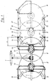
- a U-shaped bracket (1) is used to connect the rotary hay machine to the three-point linkage of a tractor. From it a carrier (2) leads to the main frame (3) of the machine. At both ends of the inner support arms (4) are pivoted about axes (5). At the free ends of the inner support arms (4), outer support arms (6) are pivoted about axes (7).
- the inner support arms (4) and the outer support arms (6) each carry a gyroscope (8) and an impeller (9), while the main frame (3) carries two gyroscopes (8 ') and two impellers (9).
- the tine tips (10) of the rotors (8, 8 ') are directed towards the ground in the working position, while in the transport position they protrude outwards from the machine when the rotors (8) are folded up.
- the inner support arms (4) and the outer support arms (6) can be raised into the transport position or lowered into the working position by means of hydraulic lifting cylinders (11) (FIG. 2).
- U-shaped inner protective brackets (12) are attached to the main frame (3). Their free ends (13) have pivot axes (14) pointing in the direction of travel at a distance a from the axes (5).
- Rod-shaped protective devices (15) are attached to these device.
- the two rod-shaped protective devices (15) can also be connected to one another at their free ends by a rod (not shown).
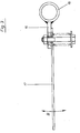
- the rod-shaped protective devices (15) have tabs (16), on which protective flaps (17) are attached in a spring-loaded manner, so that they can dodge in the direction of the double arrow B (FIGS. 1 and 3).
- Stops (19) extending in the direction of travel are attached to the inner support arms (4), which in the working position lie above the rod-shaped protective devices (15) and hold them down. If the inner and outer support arms (4, 6) are folded up, the rod-shaped protective devices (15) can also move upwards under the action of the springs (18) until they have reached a vertical position. The tine tips (10) have to sweep past the protective flaps (17), which can deflect elastically and then assume the position shown in solid lines in FIG. 1. The tine tips are now covered by the rod-shaped protective devices (15) from the front and rear and by the protective flaps (17) from the side. This means that accident protection is satisfied.
- the rod-shaped protective devices (15) are extended beyond their pivot axes (14) by a free leg (20) with a foot plate (21) (Fig. 2) so that they touch the ground in the vertical position and thus the parked machine additionally support.
Landscapes
- Life Sciences & Earth Sciences (AREA)
- Environmental Sciences (AREA)
- Agricultural Machines (AREA)
- Soil Working Implements (AREA)
- Spinning Or Twisting Of Yarns (AREA)
- Connector Housings Or Holding Contact Members (AREA)
- Emergency Protection Circuit Devices (AREA)
- Gyroscopes (AREA)
- Harvester Elements (AREA)
Description
- Die Erfindung bezieht sich auf eine Schutzvorrichtung für Kreiselheumaschinen nach dem Oberbegriff des Anspruches 1. Eine Schutzvorrichtung dieser Art ist zum Beispiel in der Europäischen Patentanmeldung 00 83 460 dargestellt und beschrieben. Bei der bekannten Ausführung werden die im Betrieb umlaufenden Zinkenträger von vorn und die in der Transportstellung stillstehenden Zinkenspitzen ebenfalls von vorn abgedeckt. Der dafür aufwendige Bauaufwand ist aber erheblich. Außerdem ist der Schutz für die Kreisel unvollständig. Ein wesentlicher Nachteil besteht ferner darin, daß der Schutzbügel in der Transportstellung von einem entgegenkommenden Fußgänger, Fahrzeug oder einem feststehenden Hindernis erfaßt werden und dadurch entgegen der Wirkung einer Feder weiter als beabsichtigt in den Verkehrsraum hinein verschwenkt werden kann, was zu Unfällen führen kann.
- Alle diese Nachteile können mit einer Ausführung nach der Erfindung vermieden werden.
- Durch Maßnahmen, die im Anspruch 1 (Fassung A) offenbart sind, wird auf eine einfache und kostensparende Weise erreicht, daß die Kreisel sowohl in der Arbeit, als auch beim Transport von vorn, wie auch von hinten geschützt sind, und daß die hochgeklappten Kreisel an keiner Stelle über die Schutzvorrichtung hinaus in den Verkehrsraum hineinragen. Darüberhinaus haben die Schutzvorrichtungen durch ihre in Fahrtrichtung liegenden Achsen eine feste Abstützung zum Maschinengestell, wodurch erhebliche Kräfte in oder gegen die Fahrtrichtung aufgenommen werden können.
- Durch die im Anspruch 2 (Fassung A) offenbarten Maßnahmen wird erreicht, daß das Verschwenken der Schutzvorrichtungen in die Transportstellung selbsttätig erfolgt und das Verschwenken in die Arbeitsstellung durch die abgeklappten Kreisel zwangsweise bewirkt wird.
- In der älteren, gegenüber diesem Anmeldungsgegenstand nicht vorveröffentlichten Euro-Patentanmeldung 0310532 ist eine Schutzvorrichtung für Kreiselheumaschinen entsprechend dem Oberbegriff des Anspruches 1 (Fassung B) beschrieben, bei der verschwenkbare Schutzvorrichtungen - in Fahrtrichtung gesehen - vor und hinter den hochklappbaren Zinkenkreiseln angeordnet und um in Fahrtrichtung und außerhalb der Schwenkachsen für die hochklappbaren Kreisel liegende Achsen so nach oben und unten verschwenkbar sind, daß sie in der Arbeit die umlaufenden Zinkenträger der Zinkenkreisel und beim Transport die Zinkenspitzen abdecken. Gegenüber diesem älteren Vorschlag unterscheidet sich der Anmeldungsgegenstand entsprechend dem Kennzeichen des unabhängigen Anspruches 1 (Fassung B) dadurch, daß die Schutzvorrichtung durch Federkraft nach oben in eine etwa senkrechte Stellung und entgegen einer Federkraft durch Anschläge an den Tragarmen für die hochklappbaren Zinkenkreisel nach unten in eine etwa waagrechte Stellung schwenkbar sind.
- Eine Vorteilhafte Ausbildung der Schutzvorrichtung erlaubt es, bei Kreiselheumaschinen mit 3-Punkt-Anbau am Schlepper ohne großen Mehraufwand zusätzliche Stützen für die aus der Transportstellung abgebaute und abgestellte Maschine zu bekommen.
- Nach einer weiteren Vorteilhaften Ausgestaltung der Erfindung sind an den schwenkbaren Schutzvorrichtungen elastisch oder gefedert ausweichbare Schutzklappen angebracht, die in der Transportstellung die Zinkenspitzen mindestens zum Teil von der Seite her abdecken.
- Die Erfindung wird am Beispiel einer Kreiselheumaschine mit 6 Kreiseln erläutert, von denen auf jeder Seite 2 Kreisel zum Transport hochklappbar angelenkt sind.
- Fig. 1 zeigt eine Maschine nach der Erfindung in einer Ansicht von oben, wobei 2 linke Kreisel nicht dargestellt sind. Ausgezogen ist die Transportstellung gezeichnet, strich-punktiert die Arbeitsstellung.
- Fig. 2 zeigt den gleichen Gegenstand in einer Ansicht von hinten.
- Fig. 3 zeigt eine Schutzklappe vergrößert dargestellt in einer Ansicht in Richtung des Pfeiles A (Fig. 1).
- Ein U-förmiger Bügel (1) dient zum Anschluß der Kreiselheumaschine an das Dreipunktgestänge eines Schleppers. Von ihm führt ein Träger (2) zum Hauptrahmen (3) der Maschine. An dessen beiden Enden sind innere Tragarme (4) um Achsen (5) schwenkbar angelenkt. An den freien Enden der inneren Tragarme (4) sind äußere Tragarme (6) um Achsen (7) schwenkbar angelenkt. Die inneren Tragarme (4) und die äußeren Tragarme (6) tragen je einen Kreisel (8) und ein Laufrad (9), während der Hauptrahmen (3) zwei Kreisel (8') und zwei Laufräder (9) trägt. Die Zinkenspitzen (10) der Kreisel (8, 8') sind in der Arbeitsstellung zum Boden hin gerichtet, während sie in der Transportstellung bei den hochklappbaren Kreiseln (8) nach außen gerichtet von der Maschine abstehen. Die inneren Tragarme (4) und die äußeren Tragarme (6) können mittels hydraulischer Hubzylinder (11) in die Transportstellung gehoben oder in die Arbeitsstellung abgesenkt werden (Fig. 2).
- Am Hauptrahmen (3) sind U-förmige innere Schutzbügel (12) befestigt. Deren freie Enden (13) haben im Abstand a von den Achsen (5) in Fahrtrichtung zeigende Schwenkachsen (14). An diesen sind stabförmige Schutzvorrichtungen (15) gelagert. Die beiden stabförmigen Schutzvorrichtungen (15) können an ihren freien Enden auch durch einen nicht dargestellten Stab miteinander verbunden sein. Die stabförmigen Schutzvorrichtungen (15) besitzen Lappen (16), an denen Schutzklappen (17) gefedert befestigt sind, so daß sie im Sinne des Doppelpfeiles B ausweichen können (Fig. 1 und 3).
- Zugfedern (18), die einerseits an den freien Enden (13) der inneren Schutzbügel (12) und andererseits an den stabförmigen Schutzvorrichtungen (15) befestigt sind, können diese bis in eine durch nicht dargestellte Anschläge begrenzte Senkrechtstellung hoch-ziehen.
- An den inneren Tragarmen (4) sind sich in Fahrtrichtung erstrekkende Anschläge (19) befestigt, die in der Arbeitsstellung über den stabförmigen Schutzvorrichtungen (15) liegen und diese nach unten halten. Wenn die inneren und äußeren Tragarme (4, 6) nach oben geklappt werden, können sich die stabförmigen Schutzvorrichtungen (15) unter Wirkung der Federn (18) ebenfalls nach oben bewegen, bis sie eine Senkrechtlage erreicht haben. Die Zinkenspitzen (10) müssen dabei an den Schutzklappen (17) vorbeistreichen, die dabei elastisch ausweichen können und danach die in Fig. 1 ausgezogene dargestellte Lage einnehmen. Die Zinkenspitzen sind jetzt durch die stabförmigen Schutzvorrichtungen (15) von vorn und hinten und durch die Schutzklappen (17) von der Seite abgedeckt. Dadurch ist dem Unfallschutz Genüge getan.
- Die stabförmigen Schutzvorrichtungen (15) sind über ihre Schwenkachsen (14) hinaus durch einen freien Schenkel (20) mit einer Fußplatte (21) (Fig. 2) soweit verlängert, daß sie in der senkrechten Lage den Boden berühren und so die abgestellte Maschine zusätzlich stützen.
Claims (4)
Priority Applications (1)
| Application Number | Priority Date | Filing Date | Title |
|---|---|---|---|
| AT88116369T ATE92240T1 (de) | 1987-11-19 | 1988-10-04 | Schutzvorrichtung fuer kreiselheumaschinen. |
Applications Claiming Priority (2)
| Application Number | Priority Date | Filing Date | Title |
|---|---|---|---|
| DE19873739114 DE3739114C2 (de) | 1987-11-19 | 1987-11-19 | Schutzvorrichtung für Kreiselheumaschinen |
| DE3739114 | 1987-11-19 |
Publications (4)
| Publication Number | Publication Date |
|---|---|
| EP0316559A2 EP0316559A2 (de) | 1989-05-24 |
| EP0316559A3 EP0316559A3 (en) | 1990-08-08 |
| EP0316559B1 true EP0316559B1 (de) | 1993-08-04 |
| EP0316559B2 EP0316559B2 (de) | 1998-12-02 |
Family
ID=6340732
Family Applications (1)
| Application Number | Title | Priority Date | Filing Date |
|---|---|---|---|
| EP88116369A Expired - Lifetime EP0316559B2 (de) | 1987-11-19 | 1988-10-04 | Schutzvorrichtung für Kreiselheumaschinen |
Country Status (3)
| Country | Link |
|---|---|
| EP (1) | EP0316559B2 (de) |
| AT (1) | ATE92240T1 (de) |
| DE (1) | DE3882912D1 (de) |
Families Citing this family (3)
| Publication number | Priority date | Publication date | Assignee | Title |
|---|---|---|---|---|
| FR2678804B1 (fr) * | 1991-07-11 | 1998-09-18 | Kuhn Sa | Machine de fenaison comportant au moins une roue rateleuse, un dispositif de protection et un deflecteur reglable. |
| NL2011137C2 (en) * | 2013-07-11 | 2015-01-13 | Forage Innovations Bv | Agricultural machine, in particular a haymaking machine. |
| FR3046025B1 (fr) | 2015-12-29 | 2018-01-19 | Kuhn Sa | Machine de fenaison avec un moyen de protection contre les projections |
Family Cites Families (3)
| Publication number | Priority date | Publication date | Assignee | Title |
|---|---|---|---|---|
| FR2063497A5 (de) * | 1969-10-14 | 1971-07-09 | Kuhn Freres & Cie | |
| NL188013B (nl) * | 1981-12-22 | 1991-10-16 | Lely Nv C Van Der | Landbouwwerktuig. |
| FR2621213B1 (fr) * | 1987-10-01 | 1990-01-05 | Kuhn Sa | Machine de fenaison avec un dispositif de protection perfectionne |
-
1988
- 1988-10-04 AT AT88116369T patent/ATE92240T1/de not_active IP Right Cessation
- 1988-10-04 DE DE8888116369T patent/DE3882912D1/de not_active Expired - Lifetime
- 1988-10-04 EP EP88116369A patent/EP0316559B2/de not_active Expired - Lifetime
Also Published As
| Publication number | Publication date |
|---|---|
| EP0316559A2 (de) | 1989-05-24 |
| EP0316559B2 (de) | 1998-12-02 |
| ATE92240T1 (de) | 1993-08-15 |
| DE3882912D1 (de) | 1993-09-09 |
| EP0316559A3 (en) | 1990-08-08 |
Similar Documents
| Publication | Publication Date | Title |
|---|---|---|
| EP0484794B1 (de) | Heuwerbungsmaschine | |
| EP0147832A2 (de) | Landwirtschaftlich nutzbares Arbeitsgerät | |
| EP0391093A1 (de) | Landwirtschaftliche Arbeitsmaschine | |
| DE69417122T2 (de) | Lader mit einem Paar von in Querrichtung versetzten, aufrechten Pfosten | |
| DE3632767C2 (de) | ||
| EP2591653A1 (de) | Heuwerbungsmaschine | |
| DE8712165U1 (de) | Schutzvorrichtung für Heuwerbungsmaschinen | |
| EP0316559B2 (de) | Schutzvorrichtung für Kreiselheumaschinen | |
| EP0571794B1 (de) | Landwirtschaftliche Arbeitsmaschine, besonders Kreiselheuwender | |
| DE3739114C2 (de) | Schutzvorrichtung für Kreiselheumaschinen | |
| AT393344B (de) | Kreiselheuwerbungsmaschine | |
| EP0288416B1 (de) | Heuwerbungsmaschine | |
| DE8709233U1 (de) | Kreiselheuwerbungsmaschine | |
| DE7035764U (de) | Schutzvorrichtungen fuer kreisellandmaschinen. | |
| DE19618839B4 (de) | Doppelkreiselschwader | |
| EP1046335B1 (de) | Heuwerbungsmaschine mit verstellbarem Prallelement | |
| DE4042158C2 (de) | ||
| DE2529928C2 (de) | Anbauvorrichtung für eine landwirtschaftliche Maschine | |
| DE8706316U1 (de) | Fahrgestell für eine Heuwerbungsmaschine | |
| EP0193010B1 (de) | An einem Fahrzeug aufgehängte Verteil- oder Sprüheinrichtung | |
| DE8812616U1 (de) | Heuwerbungsmaschine | |
| EP0269880B1 (de) | Düngerstreuer mit Seitenauslegern und Hebevorrichtung | |
| EP1488681B1 (de) | Heuwerbungsmaschine | |
| EP0709019A1 (de) | Kreiselschwader | |
| DE8100752U1 (de) | Anbaugeraet fuer einen weinbergschlepper o.dgl. |
Legal Events
| Date | Code | Title | Description |
|---|---|---|---|
| PUAI | Public reference made under article 153(3) epc to a published international application that has entered the european phase |
Free format text: ORIGINAL CODE: 0009012 |
|
| AK | Designated contracting states |
Kind code of ref document: A2 Designated state(s): AT BE CH DE FR IT LI NL SE |
|
| 17P | Request for examination filed |
Effective date: 19891116 |
|
| PUAL | Search report despatched |
Free format text: ORIGINAL CODE: 0009013 |
|
| AK | Designated contracting states |
Kind code of ref document: A3 Designated state(s): AT BE CH DE FR IT LI NL SE |
|
| 17Q | First examination report despatched |
Effective date: 19920227 |
|
| GRAA | (expected) grant |
Free format text: ORIGINAL CODE: 0009210 |
|
| AK | Designated contracting states |
Kind code of ref document: B1 Designated state(s): AT BE CH DE FR IT LI NL SE |
|
| PG25 | Lapsed in a contracting state [announced via postgrant information from national office to epo] |
Ref country code: NL Free format text: LAPSE BECAUSE OF FAILURE TO SUBMIT A TRANSLATION OF THE DESCRIPTION OR TO PAY THE FEE WITHIN THE PRESCRIBED TIME-LIMIT Effective date: 19930804 Ref country code: FR Free format text: LAPSE BECAUSE OF FAILURE TO SUBMIT A TRANSLATION OF THE DESCRIPTION OR TO PAY THE FEE WITHIN THE PRESCRIBED TIME-LIMIT Effective date: 19930804 |
|
| REF | Corresponds to: |
Ref document number: 92240 Country of ref document: AT Date of ref document: 19930815 Kind code of ref document: T |
|
| ITF | It: translation for a ep patent filed | ||
| REF | Corresponds to: |
Ref document number: 3882912 Country of ref document: DE Date of ref document: 19930909 |
|
| ET | Fr: translation filed | ||
| PLBI | Opposition filed |
Free format text: ORIGINAL CODE: 0009260 |
|
| 26 | Opposition filed |
Opponent name: MAASLAND N.V. Effective date: 19940426 |
|
| NLR1 | Nl: opposition has been filed with the epo |
Opponent name: MAASLAND N.V. |
|
| EAL | Se: european patent in force in sweden |
Ref document number: 88116369.5 |
|
| PGFP | Annual fee paid to national office [announced via postgrant information from national office to epo] |
Ref country code: FR Payment date: 19971027 Year of fee payment: 10 |
|
| PGFP | Annual fee paid to national office [announced via postgrant information from national office to epo] |
Ref country code: NL Payment date: 19971031 Year of fee payment: 10 |
|
| PLAW | Interlocutory decision in opposition |
Free format text: ORIGINAL CODE: EPIDOS IDOP |
|
| APAC | Appeal dossier modified |
Free format text: ORIGINAL CODE: EPIDOS NOAPO |
|
| APAE | Appeal reference modified |
Free format text: ORIGINAL CODE: EPIDOS REFNO |
|
| APAC | Appeal dossier modified |
Free format text: ORIGINAL CODE: EPIDOS NOAPO |
|
| PLAW | Interlocutory decision in opposition |
Free format text: ORIGINAL CODE: EPIDOS IDOP |
|
| PLAW | Interlocutory decision in opposition |
Free format text: ORIGINAL CODE: EPIDOS IDOP |
|
| PUAH | Patent maintained in amended form |
Free format text: ORIGINAL CODE: 0009272 |
|
| STAA | Information on the status of an ep patent application or granted ep patent |
Free format text: STATUS: PATENT MAINTAINED AS AMENDED |
|
| 27A | Patent maintained in amended form |
Effective date: 19981202 |
|
| AK | Designated contracting states |
Kind code of ref document: B2 Designated state(s): AT BE CH DE FR IT LI NL SE |
|
| REG | Reference to a national code |
Ref country code: CH Ref legal event code: AEN Free format text: AUFRECHTERHALTUNG DES PATENTES IN GEAENDERTER FORM |
|
| NLR2 | Nl: decision of opposition | ||
| EN | Fr: translation not filed | ||
| NLV1 | Nl: lapsed or annulled due to failure to fulfill the requirements of art. 29p and 29m of the patents act | ||
| PGFP | Annual fee paid to national office [announced via postgrant information from national office to epo] |
Ref country code: SE Payment date: 19991026 Year of fee payment: 12 |
|
| PGFP | Annual fee paid to national office [announced via postgrant information from national office to epo] |
Ref country code: CH Payment date: 19991223 Year of fee payment: 12 |
|
| PG25 | Lapsed in a contracting state [announced via postgrant information from national office to epo] |
Ref country code: SE Free format text: THE PATENT HAS BEEN ANNULLED BY A DECISION OF A NATIONAL AUTHORITY Effective date: 20001030 |
|
| PG25 | Lapsed in a contracting state [announced via postgrant information from national office to epo] |
Ref country code: LI Free format text: LAPSE BECAUSE OF NON-PAYMENT OF DUE FEES Effective date: 20001031 Ref country code: CH Free format text: LAPSE BECAUSE OF NON-PAYMENT OF DUE FEES Effective date: 20001031 |
|
| PGFP | Annual fee paid to national office [announced via postgrant information from national office to epo] |
Ref country code: BE Payment date: 20001205 Year of fee payment: 13 |
|
| REG | Reference to a national code |
Ref country code: CH Ref legal event code: PL |
|
| EUG | Se: european patent has lapsed |
Ref document number: 88116369.5 |
|
| PG25 | Lapsed in a contracting state [announced via postgrant information from national office to epo] |
Ref country code: BE Free format text: LAPSE BECAUSE OF NON-PAYMENT OF DUE FEES Effective date: 20011031 |
|
| BERE | Be: lapsed |
Owner name: CLAAS SAULGAU G.M.B.H. Effective date: 20011031 |
|
| PGFP | Annual fee paid to national office [announced via postgrant information from national office to epo] |
Ref country code: DE Payment date: 20021009 Year of fee payment: 15 |
|
| PGFP | Annual fee paid to national office [announced via postgrant information from national office to epo] |
Ref country code: AT Payment date: 20021023 Year of fee payment: 15 |
|
| PG25 | Lapsed in a contracting state [announced via postgrant information from national office to epo] |
Ref country code: AT Free format text: LAPSE BECAUSE OF NON-PAYMENT OF DUE FEES Effective date: 20031004 |
|
| PG25 | Lapsed in a contracting state [announced via postgrant information from national office to epo] |
Ref country code: DE Free format text: LAPSE BECAUSE OF THE APPLICANT RENOUNCES Effective date: 20031018 |
|
| PG25 | Lapsed in a contracting state [announced via postgrant information from national office to epo] |
Ref country code: IT Free format text: LAPSE BECAUSE OF NON-PAYMENT OF DUE FEES;WARNING: LAPSES OF ITALIAN PATENTS WITH EFFECTIVE DATE BEFORE 2007 MAY HAVE OCCURRED AT ANY TIME BEFORE 2007. THE CORRECT EFFECTIVE DATE MAY BE DIFFERENT FROM THE ONE RECORDED. Effective date: 20051004 |
|
| APAH | Appeal reference modified |
Free format text: ORIGINAL CODE: EPIDOSCREFNO |