EP0316271B1 - Method for modifying the ignition pressure of a self-igniting combustion engine, and apparatus for carrying out the method - Google Patents
Method for modifying the ignition pressure of a self-igniting combustion engine, and apparatus for carrying out the method Download PDFInfo
- Publication number
- EP0316271B1 EP0316271B1 EP88810730A EP88810730A EP0316271B1 EP 0316271 B1 EP0316271 B1 EP 0316271B1 EP 88810730 A EP88810730 A EP 88810730A EP 88810730 A EP88810730 A EP 88810730A EP 0316271 B1 EP0316271 B1 EP 0316271B1
- Authority
- EP
- European Patent Office
- Prior art keywords
- injection
- signals
- positioning element
- exhibits
- combustion engine
- Prior art date
- Legal status (The legal status is an assumption and is not a legal conclusion. Google has not performed a legal analysis and makes no representation as to the accuracy of the status listed.)
- Expired - Lifetime
Links
Images

Classifications
-
- F—MECHANICAL ENGINEERING; LIGHTING; HEATING; WEAPONS; BLASTING
- F02—COMBUSTION ENGINES; HOT-GAS OR COMBUSTION-PRODUCT ENGINE PLANTS
- F02D—CONTROLLING COMBUSTION ENGINES
- F02D35/00—Controlling engines, dependent on conditions exterior or interior to engines, not otherwise provided for
- F02D35/02—Controlling engines, dependent on conditions exterior or interior to engines, not otherwise provided for on interior conditions
- F02D35/023—Controlling engines, dependent on conditions exterior or interior to engines, not otherwise provided for on interior conditions by determining the cylinder pressure
-
- F—MECHANICAL ENGINEERING; LIGHTING; HEATING; WEAPONS; BLASTING
- F02—COMBUSTION ENGINES; HOT-GAS OR COMBUSTION-PRODUCT ENGINE PLANTS
- F02D—CONTROLLING COMBUSTION ENGINES
- F02D41/00—Electrical control of supply of combustible mixture or its constituents
- F02D41/30—Controlling fuel injection
- F02D41/38—Controlling fuel injection of the high pressure type
- F02D41/40—Controlling fuel injection of the high pressure type with means for controlling injection timing or duration
- F02D41/401—Controlling injection timing
-
- F—MECHANICAL ENGINEERING; LIGHTING; HEATING; WEAPONS; BLASTING
- F02—COMBUSTION ENGINES; HOT-GAS OR COMBUSTION-PRODUCT ENGINE PLANTS
- F02B—INTERNAL-COMBUSTION PISTON ENGINES; COMBUSTION ENGINES IN GENERAL
- F02B3/00—Engines characterised by air compression and subsequent fuel addition
- F02B3/06—Engines characterised by air compression and subsequent fuel addition with compression ignition
-
- F—MECHANICAL ENGINEERING; LIGHTING; HEATING; WEAPONS; BLASTING
- F02—COMBUSTION ENGINES; HOT-GAS OR COMBUSTION-PRODUCT ENGINE PLANTS
- F02F—CYLINDERS, PISTONS OR CASINGS, FOR COMBUSTION ENGINES; ARRANGEMENTS OF SEALINGS IN COMBUSTION ENGINES
- F02F7/00—Casings, e.g. crankcases or frames
- F02F2007/0097—Casings, e.g. crankcases or frames for large diesel engines
-
- Y—GENERAL TAGGING OF NEW TECHNOLOGICAL DEVELOPMENTS; GENERAL TAGGING OF CROSS-SECTIONAL TECHNOLOGIES SPANNING OVER SEVERAL SECTIONS OF THE IPC; TECHNICAL SUBJECTS COVERED BY FORMER USPC CROSS-REFERENCE ART COLLECTIONS [XRACs] AND DIGESTS
- Y02—TECHNOLOGIES OR APPLICATIONS FOR MITIGATION OR ADAPTATION AGAINST CLIMATE CHANGE
- Y02T—CLIMATE CHANGE MITIGATION TECHNOLOGIES RELATED TO TRANSPORTATION
- Y02T10/00—Road transport of goods or passengers
- Y02T10/10—Internal combustion engine [ICE] based vehicles
- Y02T10/40—Engine management systems
Definitions
- the invention relates to a method for changing the mean effective pressure of a self-igniting reciprocating piston internal combustion engine by adjusting the start of injection of the fuel injector, based on the angle of rotation of the crankshaft, electrical signals corresponding to the instantaneous load state of the internal combustion engine being generated, these signals one are supplied to electronic circuit which has a memory. Furthermore, the invention relates to a device for changing the mean effective pressure of a self-igniting reciprocating internal combustion engine with means for adjusting the start of injection of the fuel injection device, based on the angle of rotation of the crankshaft, continuously the current load condition corresponding electrical signals are generated to the internal combustion engine, these signals are supplied to an electronic circuit which has a memory.
- the injection pumps have, for example, a suction valve and an overflow valve, both of which are closed at the start of injection and during injection.
- the injection process is ended by opening the overflow valve.
- the mean effective ignition pressure of the diesel engines is changed as the injection duration is shortened or lengthened by opening the overflow valve at a later point in time and thus injecting a larger amount of fuel per ignition cycle of the engine.
- This change in the injection quantity or injection duration takes place, for example, in large diesel engines by, depending on the power requirement, the eccentric control of the overflow valve by e.g. Twisting an eccentric shaft is influenced by a linkage.
- the timing of the start of injection can be changed within certain limits, with the injection quantity and injection duration remaining the same. In other words, this means that the fuel is injected in a different but equally large rotation angle range of the crankshaft or range of the piston path.
- the mean effective ignition pressure - also called simply ignition pressure - changes over the load range by changing the start of injection and is shown in ignition pressure characteristic curves. It is also known from the engines at which angle of rotation of the crankshaft under a certain load or power Injection process should take place, for example, to achieve the best efficiency.
- the engine Depending on the desired operating mode, it is therefore possible to operate the engine according to the associated ignition pressure characteristic.
- the timing of the injection takes place, for example, in that the eccentric control of the suction and overflow valve of the pump influences in the same direction as a function of the output characteristic curve, that is to say is changed.
- a cam disk is used which is positioned according to the desired mean ignition pressure and which acts on the eccentric shafts of the suction and overflow valve of the injection pump via a linkage.
- a cam or control disc is designed for a very specific ignition pressure characteristic of the engine.
- the operation of the diesel engine according to a different output characteristic requires extensive conversion and adjustment work and in particular the shutdown of the engine. Such conversions are costly and disruptive to operation.
- the publication SAE 860145 describes an injection system for vehicle diesel engines, in which the injection quantity and start of injection are influenced by various control variables, such as speed, accelerator pedal position, engine load, water temperature, etc.
- This device has a memory with control variables for different engine types, which makes the injection control suitable for different vehicle engine types.
- the object of the invention is to provide a simplified method with which self-igniting reciprocating piston internal combustion engines, for example diesel engines, can optionally be operated according to various output characteristics.
- a method is characterized in that the values of a plurality of characteristic curves of the mean effective pressure of the internal combustion engine are stored, and that the Electronic circuit has a circuit which, from the stored values of one of these characteristic curves, generates signals for the position of the actuator for controlling the start of injection with a first valve and the end of injection with a second valve, and these signals are fed to the downstream actuator and thus its position determine, with the load remaining the injection duration of the injection device remains the same.
- the dependent method claims relate to particularly advantageous forms of the method.
- the device according to the invention is characterized by the features in the characterizing part of claim 4. It allows the procedure to be carried out in a simple manner.
- the dependent device claims relate to particularly advantageous designs of such devices.
- the process enables diesel engines to be operated immediately with the best possible efficiency without extensive modifications to the engine, optionally according to various characteristic curves of the mean effective pressure. It is possible to replace the memory in the electronic circuit, to enter the values of the new characteristic into the memory, or to include the values of the new characteristic already in the memory in the injection control.
- the method also makes it possible to adapt or change the area of the characteristic curve of the mean effective pressure which deviates from the normal curve, that is to say the area in which the start of injection may be shifted, to the selected full-load position of a diesel engine.
- the method also has the advantage that the adjusting forces when the start of injection is shifted are not transmitted to the rotary encoder.
- the circuit 1 shown in FIG. 1 for determining the displacement of the start of injection essentially comprises a converter, for example a current-voltage converter 11, in which a signal coming from an angle encoder 2, which is a Measure of the operating state of the diesel engine is standardized.
- the values of ignition pressure characteristic curves (characteristic curves of the mean effective pressure) of the engine are stored in the memory circuit 12.
- the motor is operated according to one of these stored characteristics.
- Each of the values includes a specific point in time, related to the angle of rotation ⁇ (fi) of the crankshaft, of the start of the injection process of the injection pump.
- the memory circuit 12 can calculate this point in time, but it is also possible to save the associated value of the start of injection for each operating state of the diesel engine in the manner of a value table and to call it up as required.
- the switch to operating the engine according to another output characteristic curve can be made in terms of circuitry if several characteristic curves are stored in the memory 12. However, the entire memory 12 in the circuit 1 can also be exchanged or reloaded.
- the signal of the storage circuit is fed to a summing circuit 13.
- the signal which determines the time of the start of injection can be changed further with parameter signals.
- a correction value can be entered with a potentiometer circuit 14, which takes into account the ignition properties of the fuel or fuel currently being used.
- the parameter signals can be input both on the control electronics themselves or from a remote input device 14.
- the output signal of the summing circuit 13 is fed to the converter 15, which processes the signal for the actuator 16.
- the actuator 16 can for example be operated hydraulically, pneumatically or by an electric motor and act with the rod only symbolized here on the eccentric shaft of the injector 3 'and change the time of the start of injection.
- the actuator 16 in a control loop in which the position of the actuator is continuously a controller 17 is supplied, which continuously transmits correction signals (dashed line) to the converter 15 from the actual position of the actuator and a desired position signal retrieved from the memory.
- the direct connection between the summing circuit 13 and converter 17 would of course be omitted and, conversely, the controller and its connections are omitted if a controller without a closed control loop is used.
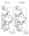
- FIGS. 2A and 2B show the setting of the injection pump 3 for two different load conditions of the diesel engine with different times of the start of injection.
- the fuel is fed to the injection pump via the supply line 35 with the suction valve 32 and injected into the cylinder of the diesel engine via the injection line 36.
- the injection process is ended by opening the overflow valve 31 and the fuel then flows back via the overflow line 34.
- the operating state of the diesel engine is indicated by the position of the lever 40 of the rotary encoder 4, which at the same time via a linkage with rotary levers and rods 41, 42, 43, 44, 45, 46, 47, 48, 49, the opening time for the overflow valve 31 of the injection pump 3 influenced, ie with constant start of injection, the overflow valve 31 opens later at higher output and earlier at lower output.
- the signal corresponding to the angular position of the lever 40 of the circuit 1' is fed to adjust the time of the start of injection.
- the circuit 1 'then determines a control signal which determines the position of the piston 160 of the actuator 16'.
- the piston rod 160 ' is connected to the lever 164 and causes the front and Moving backwards in the same direction changing the control of the two valves 31 and 32 with the eccentric shafts, which changes the shift in the time of the start of injection, but not the injection duration, ie the injection quantity per injection stroke of the injection pump.
- FIG. 2B an angular position of the lever 40 of the rotary encoder 4 and the position of the rods and levers 41, 42, 43, 44, 45, 46, 47, 48, 49, which are coupled to it, are shown differently from FIG. 2A.
- the position of the lever 164 with the piston rod 160 'of the actuator 16' is also changed.
- This change in position influences the eccentric shaft control of the two valves 31 and 32 in such a way that the start of injection, relative to the angle of rotation of the crankshaft of the diesel engine, shifts in time with the same injection duration and injection quantity.
- the respective position of the piston rod 160 'of the actuator 16' is determined by the circuit 1 'based on the signal for the angular position of the lever 40 of the rotary encoder 4 from the values stored in the memory of the circuit 1', e.g. an ignition pressure characteristic curve of the diesel engine.
- the course of the output characteristic curve a which deviates from the normal curve n (also called natural curve or basic curve), in the range between 50% and 100% power, ie between points A ′ via A ⁇ to A130, is achieved by shifting the time of the start of injection.
- 50% power output characteristic curve a and normal curve n run in the shown Example the same, which means that the shifting device does not need to be effective for the start of injection in this area, but the actuator can assume a fixed starting position.
- the engine can be operated according to a different output characteristic.
Description
Die Erfindung bezieht sich auf ein Verfahren zum Verändern des mittleren effektiven Drucks einer selbstzündenden Hubkolben-Brennkraftmaschine durch Verstellen des Einspritzbeginns der Brennstoff-Einspritzvorrichtung, bezogen auf den Drehwinkel der Kurbelwelle, wobei laufend dem momentanen Belastungszustand der Brennkraftmaschine entsprechende elektrische Signale erzeugt werden, diese Signale einer elektronischen Schaltung zugeführt werden, die einen Speicher aufweist. Weiter bezieht sich die Erfindung auf eine Vorrichtung zum Verändern des mittleren effektiven Drucks einer selbstzündenden Hubkolben-Brennkraftmaschine mit Mitteln zum Verstellen des Einspritzbeginns der Brennstoff-Einspritz vorrichtung, bezogen auf den Drehwinkel der Kurbelwelle, wobei laufend dem momentanen Belastungszustand der Brennkraftmaschine entsprechende elektrische Signale erzeugt werden, diese Signale einer elektronischen Schaltung zugeführt werden, die einen Speicher aufweist.The invention relates to a method for changing the mean effective pressure of a self-igniting reciprocating piston internal combustion engine by adjusting the start of injection of the fuel injector, based on the angle of rotation of the crankshaft, electrical signals corresponding to the instantaneous load state of the internal combustion engine being generated, these signals one are supplied to electronic circuit which has a memory. Furthermore, the invention relates to a device for changing the mean effective pressure of a self-igniting reciprocating internal combustion engine with means for adjusting the start of injection of the fuel injection device, based on the angle of rotation of the crankshaft, continuously the current load condition corresponding electrical signals are generated to the internal combustion engine, these signals are supplied to an electronic circuit which has a memory.
Grosse, selbstzündende Hubkolben-Brennkraftmaschinen, wie Dieselmotoren, verfügen in der Regel für jeden Zylinder über eine Einspritzpumpe für den Brennstoff. Die Einspritzpumpen verfügen beispielsweise über ein Saugventil und ein Überströmventil, die beide beim Einspritzbeginn und während des Einspritzens geschlossen sind. Der Einspritzvorgang wird durch Öffnen des Überströmventils beendet. Der mittlere effektive Zünddruck der Dieselmotoren wird mit Verkürzen oder Verlängern der Einspritzdauer verändert, indem das Überströmventil zu einem späteren Zeitpunkt öffnet und damit eine grössere Brennstoffmenge pro Zündtakt des Motors eingespritzt wird. Diese Veränderung der Einspritzmenge bzw. Einspritzdauer erfolgt beispielsweise bei Grossdieselmotoren, indem je nach Leistungbedarf die Exzentersteuerung des Überströmventils durch z.B. Verdrehen einer Exzenterwelle über ein Gestänge beeinflusst wird.Large, self-igniting reciprocating internal combustion engines, such as diesel engines, generally have an injection pump for the fuel for each cylinder. The injection pumps have, for example, a suction valve and an overflow valve, both of which are closed at the start of injection and during injection. The injection process is ended by opening the overflow valve. The mean effective ignition pressure of the diesel engines is changed as the injection duration is shortened or lengthened by opening the overflow valve at a later point in time and thus injecting a larger amount of fuel per ignition cycle of the engine. This change in the injection quantity or injection duration takes place, for example, in large diesel engines by, depending on the power requirement, the eccentric control of the overflow valve by e.g. Twisting an eccentric shaft is influenced by a linkage.
Um den Wirkungsgrad, d.h. die Nutzung des Brennstoffs im ganzen Betriebsbereich, zu verbessern, kann bei Dieselmotoren der Zeitpunkt des Beginns des Einspritzens, bezogen auf den Drehwinkel des Kurbelwelle, in gewissen Grenzen, bei gleichbleibender Einspritzmenge und Einspritzdauer verändert werden. Mit anderen Worten heisst das, dass der Kraftstoff in einem anderen, aber gleich grossen Drehwinkelbereich der Kurbelwelle bzw. Bereich des Kolbenweges eingespritzt wird. Von Dieselmotoren ist bekannt, wie sich der mittlere effektive Zünddruck ― auch vereinfacht Zünddruck genannt ― über den Belastungsbereich, durch Verändern des Einspritzbeginns verändert und wird in Zünddruckkennlinien dargestellt. Von den Motoren ist auch bekannt, bei welchem Drehwinkel der Kurbelwelle bei einer bestimmten Belastung bzw. Leistung der Einspritzvorgang erfolgen soll, um beispielsweise den besten Wirkungsgrad zu erzielen. Je nach gewünschter Betriebsart ist es also möglich, den Motor nach der dazugehörigen Zünddruckkennlinie zu betreiben. Die zeitliche Verschiebung des Einspritzens erfolgt z.B. dadurch, dass die Exzentersteuerung von Saug- und Überströmventil der Pumpe gleichsinnig als Funktion der Ausgangskennlinie beeinflusst, d.h. verändert wird. Bei bisherigen mechanischen Lösungen wird beispielsweise eine Kurvenscheibe eingesetzt, die entsprechend dem gewünschten mittleren Zünddruck positioniert wird und welche über ein Gestänge auf die Exzenterwellen des Saug- und des Überströmventils der Einspritzpumpe einwirkt. Eine Nocken- oder Steuerscheibe ist für eine ganz bestimmte Zünddruckkennlinie des Motors ausgelegt. Der Betrieb des Dieselmotors nach einer anderen Ausgangscharakteristik erfordert umfangreiche Umbau- und Einstellarbeiten und insbesondere das Stillegen des Motors. Derartige Umbauten sind kostenaufwendig und für den Betrieb störend.In order to improve the efficiency, ie the use of fuel in the entire operating range, the timing of the start of injection, based on the angle of rotation of the crankshaft, can be changed within certain limits, with the injection quantity and injection duration remaining the same. In other words, this means that the fuel is injected in a different but equally large rotation angle range of the crankshaft or range of the piston path. It is known from diesel engines how the mean effective ignition pressure - also called simply ignition pressure - changes over the load range by changing the start of injection and is shown in ignition pressure characteristic curves. It is also known from the engines at which angle of rotation of the crankshaft under a certain load or power Injection process should take place, for example, to achieve the best efficiency. Depending on the desired operating mode, it is therefore possible to operate the engine according to the associated ignition pressure characteristic. The timing of the injection takes place, for example, in that the eccentric control of the suction and overflow valve of the pump influences in the same direction as a function of the output characteristic curve, that is to say is changed. In previous mechanical solutions, for example, a cam disk is used which is positioned according to the desired mean ignition pressure and which acts on the eccentric shafts of the suction and overflow valve of the injection pump via a linkage. A cam or control disc is designed for a very specific ignition pressure characteristic of the engine. The operation of the diesel engine according to a different output characteristic requires extensive conversion and adjustment work and in particular the shutdown of the engine. Such conversions are costly and disruptive to operation.
In der Publikation SAE 860145 ist ein Einspritzsystem für Fahrzeug-Dieselmotoren beschrieben, bei dem Einspritzmenge und Einspritzbeginn mit verschiedenen Steuergrössen, wie Drehzahl, Gaspedalstellung, Motorlast, Wassertemperatur usw. beeinflusst werden. Diese Vorrichtung weist einen Speicher mit Steuergrössen für verschiedene Motorentypen auf, was die Einspritzsteuernung für verschiedene Fahrzeug-Motorentypen geeignet macht.The publication SAE 860145 describes an injection system for vehicle diesel engines, in which the injection quantity and start of injection are influenced by various control variables, such as speed, accelerator pedal position, engine load, water temperature, etc. This device has a memory with control variables for different engine types, which makes the injection control suitable for different vehicle engine types.
Aufgabe der Erfindung ist es, ein vereinfachtes Verfahren zu schaffen, mit dem selbstzündende Hubkolben-Brennkraftmaschinen, z.B. Dieselmotoren, wahlweise nach verschiedenen Ausgangskennlinien betrieben werden können. Erfindungsgemäss ist ein derartiges Verfahren dadurch gekennzeichnet, darin die Werte mehrerer Kennlinien des mittleren effektiven Drucks der Brennkraftmaschine gespeichert sind, und dass die elektronische Schaltung eine Schaltung aufweist, welche wahlweise, aus den gespeicherten Werten einer dieser Kennlinien Signale für die Stellung der Stellglieds zum Steuern des Einspritzbeginns mit einem ersten Ventil und des Einspritzendes mit einem zweiten Ventil erzeugt und diese Signale dem nachgeschalteten Stellglied zugeführt werden und damit dessen Position bestimmen, wobei bei gleichbleibender Last die Einspritzdauer der Einspritzvorrichtung gleich bleibt. Die abhängigen Verfahrensansprüche beziehen sich auf besonders vorteilhafte Formen des Verfahrens.The object of the invention is to provide a simplified method with which self-igniting reciprocating piston internal combustion engines, for example diesel engines, can optionally be operated according to various output characteristics. According to the invention, such a method is characterized in that the values of a plurality of characteristic curves of the mean effective pressure of the internal combustion engine are stored, and that the Electronic circuit has a circuit which, from the stored values of one of these characteristic curves, generates signals for the position of the actuator for controlling the start of injection with a first valve and the end of injection with a second valve, and these signals are fed to the downstream actuator and thus its position determine, with the load remaining the injection duration of the injection device remains the same. The dependent method claims relate to particularly advantageous forms of the method.
Die erfindungsgemässe Vorrichtung ist durch die Merkmale im Kennzeichen von Anspruch 4 gekennzeichnet. Sie erlaubt auf einfache Weise, das Verfahren durchzuführen. Die abhängigen Vorrichtungsansprüche beziehen sich auf besonders vorteilhafte Ausführungen derartiger Vorrichtungen.The device according to the invention is characterized by the features in the characterizing part of
Das Verfahren ermöglicht, Dieselmotoren ohne aufwendige Umbauarbeiten am Motor, wahlweise nach verschiedenen Kennlinien des mittleren effektiven Drucks sofort mit dem bestmöglichen Wirkungsgrad zu betreiben. Dabei ist es möglich, den Speicher in der elektronischen Schaltung auszuwechseln, die Werte der neuen Kennlinie in den Speicher einzugeben, oder die im Speicher schon vorhandenen Werte der neuen Kennlinie in die Einspritzsteuerung einzubeziehen. Das Verfahren ermöglicht aber auch die Anpassung oder Veränderung des von der Normalkurve abweichenden Bereichs der Kennlinie des mittleren effektiven Drucks, also des Bereichs, in welchem die Verschiebung des Einspritzbeginns erfolgen darf, an die gewählte Vollastposition eines Dieselmotors. Weiter ist es möglich, bei kurzzeitig ständig variierender Belastung den Lauf des Dieselmotors durch Verwenden eines Verzögerungsglieds zu beruhigen, indem die kurzzeitige Schwankungen nicht zum Verändern des Einspritzbeginns führen. Das Verfahren bringt gegenüber heutigen Lösungen mit Kurvensteuerung für die Veränderung des Einspritzbeginns, mit beispielsweise Exzenterwellen, auch den Vorteil, dass die Verstellkräfte beim Verschieben des Einspritzbeginns nicht auf den Drehwinkelgeber übertragen werden.The process enables diesel engines to be operated immediately with the best possible efficiency without extensive modifications to the engine, optionally according to various characteristic curves of the mean effective pressure. It is possible to replace the memory in the electronic circuit, to enter the values of the new characteristic into the memory, or to include the values of the new characteristic already in the memory in the injection control. However, the method also makes it possible to adapt or change the area of the characteristic curve of the mean effective pressure which deviates from the normal curve, that is to say the area in which the start of injection may be shifted, to the selected full-load position of a diesel engine. Furthermore, it is possible to run the diesel engine in the event of a constantly varying load for a short time by using a delay element to calm down by the fact that the short-term fluctuations do not change the start of injection. Compared to today's solutions with curve control for changing the start of injection, for example with eccentric shafts, the method also has the advantage that the adjusting forces when the start of injection is shifted are not transmitted to the rotary encoder.
Nachstehend werden Beispiele des Verfahrens und der Vorrichtung anhand der Zeichnungen, näher erläutert.Examples of the method and the device are explained in more detail below with reference to the drawings.
Es zeigen:
- Fig. 1
- das Blockschema eines Beispiels einer elektronischen Schaltung zum Verstellen des auf den Drehwinkel bezogenen Zeitpunkts des Einspritzbeginns einer Brennstoff-Einspritzvorrichtung;
- Fig. 2A
- schematisch eine Steuerung für einen Dieselmotor, bei welcher der Einspritzbeginn mit einem elektronisch gesteuerten Stellglied verstellbar ist, bei z.B. Nullast;
- Fig. 2B
- die Lage der Hebel der Steuerung des mittleren effektiven Zünddrucks von Fig. 2A bei z.B. Vollast;
- Fig. 3
- schematisch ein Beispiel eines Last-Zünddruck-Diagramm mit einer Zünddruckkennlinie für einen Dieselmotor.
Show it:
- Fig. 1
- the block diagram of an example of an electronic circuit for adjusting the timing of the start of injection of a fuel injector based on the angle of rotation;
- Figure 2A
- schematically shows a control for a diesel engine, in which the start of injection is adjustable with an electronically controlled actuator, for example at zero load;
- Figure 2B
- the position of the levers for controlling the mean effective ignition pressure of FIG. 2A at, for example, full load;
- Fig. 3
- schematically an example of a load-ignition pressure diagram with an ignition pressure characteristic for a diesel engine.
Die in Fig. 1 gezeigte Schaltung 1 zum Ermitteln der Verschiebung des Einpritzbeginns umfasst im wesentlichen einen Wandler, z.B. einen Strom-Spannungswandler 11, in welchem ein von einem Drehwinkelgeber 2 kommende Signal, welches ein Mass für Betriebszustand des Dieselmotors ist, normiert wird. In der Speicherschaltung 12, sind die Werte von Zünddruckkennlinien (Kennlinien des mittleren effektiven Drucks) des Motors gespeichert. Der Motor wird nach einer dieser gespeicherten Kennlinien betrieben. Zu jedem der Werte gehört ein bestimmter, auf den Drehwinkel ∅ (fi) der Kurbelwelle bezogener Zeitpunkt des Beginns des Einspritzvorgangs der Einspritzpumpe. Die Speicherschaltung 12 kann diesen Zeitpunkt berechnen, aber es ist auch möglich, zu jedem Betriebszustand des Dieselmotors den zugehörigen Wert des Einspritzbeginn, in der Art einer Wertetabelle zu speichern und bei Bedarf abzurufen. Der Wechsel zum Betrieb des Motors nach einer andern Ausgangkennlinie kann schaltungsmässig vorgenommen werden, wenn mehrere Kennlinien im Speicher 12 gespeichert sind. Es kann aber auch der ganze Speicher 12 in der Schaltung 1 ausgetauscht, oder neu geladen werden.The
Das Signal, der Speicherschaltung wird einer Sumierschaltung 13 zugeführt. In der Sumierschaltung 13 kann das Signal, welches den Zeitpunkt des Einspritzbeginns bestimmt, mit Parameter-Signalen weiter verändert werden. So kann etwa mit einer Potentiometerschaltung 14 ein Korrekturwert eingegeben werden, der die Zündeigenschaften des gerade verwendeten Treib- oder Brennstoffs berücksichtigt. Die Parameter-Signale können sowohl an der Steuerelektronik selbst oder von einem entfernt liegenden Eingabegerät 14 eingegeben werden. Das Ausgangssignal der Sumierschaltung 13 wird dem Wandler 15 zu geführt, der das Signal für das Stellglied 16 aufbereitet. Das Stellglied 16 kann beispielsweise hydraulisch, pneumatisch oder elektromotorisch betrieben werden und mit der hier nur symbolisiert gezeichneten Stange auf die Exzenterwelle der Einspritzvorrichtung 3′ einwirken und den Zeitpunkt des Einspritzbeginns verändern. Es ist auch möglich, das Stellglied 16 in einen Regelkreis einzubeziehen, bei dem die Position des Stellglieds laufend einem Regler 17 zugeführt wird, der aus der Istposition des Stellgliedes und einem vom Speicher abgerufenen Sollpositions-Signal, dem Wandler 15 laufend Korrektursignale (gestrichelte Linie) übermittelt. Bei dieser Lösung würde die direkte Verbindung zwischen Sumierschaltung 13 und Wandler 17 natürlich entfallen und umgekehrt entfällt der Regler und seine Verbindungen, wenn eine Steuerung ohne geschlossenen Regelkreis verwendet wird.The signal of the storage circuit is fed to a
In den Fig. 2A und 2B ist die Einstellung der Einspritzpumpe 3 für zwei verschiedene Belastungszustände des Dieselmotors mit verschiedenen Zeitpunkten des Einspritzbeginns gezeigt. Der Brennstoff wird der Einspritzpumpe über die Zufuhrleitung 35 mit dem Saugventil 32 zugeführt und über die Einspritzleitung 36 in den Zylinder des Dieselmotors eingespritzt. Der Einspritzvorgang wird durch das Öffnen des Überströmventils 31 beendet und der Brennstoff fliesst dann über die Überströmleitung 34 zurück.2A and 2B show the setting of the
Der Betreibszustand des Dieselmotors wird durch die Stellung des Hebels 40 des Drehgebers 4 angezeigt der gleichzeitig über ein Gestänge mit Drehhebeln und Stangen 41, 42, 43, 44, 45, 46, 47, 48, 49, den Öffnungszeitpunkt für das Überströmventil 31 der Einspritzpumpe 3 beeinflusst, d.h. bei gleichbleibendem Einspritzbeginn das Überströmventil 31 bei höherer Leistung später und beiniedrigerer Leistung früher öffnet.The operating state of the diesel engine is indicated by the position of the
Vom Drehgeber 4, der auch einen elektrischen Winkelgeber 40′ aufweist, wird das der Winkelposition des Hebels 40 entsprechende Signal der Schaltung 1′ zum Verstellen des Zeitpunktes des Einspritzbeginns zugeführt. Die Schaltung 1′ ermittelt dann ein Steuersignal, das die Lage des Kolbens 160 des Stellglieds 16′ bestimmt. Die Kolbenstange 160′ ist mit dem Hebel 164 verbunden und bewirkt beim Vor- und Rückwärtsbewegen das gleichsinnige Verändern der Steuerung der beiden Ventile 31 und 32 mit den Exzenterwellen, was die Verschiebung des Zeitpunktes des Beginns des Einspritzens, nicht aber die Einspritzdauer d.h die Einspritzmenge pro Einspritztakt der Einspritzpumpe verändert.From the
In Fig. 2B ist eine gegenüber Fig. 2A veränderte Winkel-Lage des Hebels 40 des Drehgebers 4 und der Lage der daran gekoppelten Stangen und Hebel 41, 42, 43, 44, 45, 46, 47, 48, 49, gezeigt. Zusätzlich ist aber auch die Lage des Hebels 164 mit der Kolbenstange 160' des Stellglieds 16' verändert. Diese Lageveränderung (eine vorherige Position ist strichpunktiert angedeutet) beeinflusst die Exzenterwellen-Steuerung der beiden Ventile 31 und 32 gleichsinnig so, dass sich der Beginn des Einspritzens, bezogen auf den Drehwinkel der Kurbelwelle des Dieselmotors, bei gleichbleibender Einspritzdauer und Einspritzmenge, zeitlich verschiebt. Die jeweilige Lage der Kolbenstange 160′ des Stellglieds 16′ wird durch die Schaltung 1′ aufgrund des Signal für die Winkellage des Hebels 40 des Drehgebers 4 aus den im Speicher der Schaltung 1′ gespeicherten Werten, z.B. einer Zünddruckkennlinie des Dieselmotors ermittelt.In FIG. 2B, an angular position of the
Im Last-Zünddruckdiagramm (Pz = mittlerer effektiver Zünddruck, L = Leistung in %) von Fig. 3 ist ein Beispiel einer Zünddruckkennlinie a dargestellt. Der von der Normalkurve n (auch Naturkurve oder Grundkurve genannt) abweichende Verlauf der Ausgangkennlinie a im Bereich zwischen 50% und 100% Leistung, d.h. zwischen den Punkten A′ über A˝ nach A‴ wird mit dem Verschieben des Zeitpunkts des Einspritzbeginns erreicht. Im Bereich unterhalb von 50% Leistung verlaufen Ausgangskennlinie a und Normalkurve n im gezeigten Beispiel gleich, was bedeutet, dass die Verschiebevorrichtung für den Einspritzbeginn in diesem Bereich nicht wirksam zu sein braucht, sondern das Stellglied eine feststehende Ausgangslage einnehmen kann. Je nach Dieselmotortyp und der Art seines Einsatzes, kann man den Motor nach einer andern Ausgangskennlinie betreiben.The load ignition pressure diagram (P z = mean effective ignition pressure, L = power in%) of FIG. 3 shows an example of an ignition pressure characteristic curve a. The course of the output characteristic curve a, which deviates from the normal curve n (also called natural curve or basic curve), in the range between 50% and 100% power, ie between points A ′ via A˝ to A erreicht, is achieved by shifting the time of the start of injection. In the range below 50% power output characteristic curve a and normal curve n run in the shown Example the same, which means that the shifting device does not need to be effective for the start of injection in this area, but the actuator can assume a fixed starting position. Depending on the diesel engine type and the type of use, the engine can be operated according to a different output characteristic.
Claims (12)
Applications Claiming Priority (2)
| Application Number | Priority Date | Filing Date | Title |
|---|---|---|---|
| CH4370/87 | 1987-11-10 | ||
| CH4370/87A CH673507A5 (en) | 1987-11-10 | 1987-11-10 |
Publications (2)
| Publication Number | Publication Date |
|---|---|
| EP0316271A1 EP0316271A1 (en) | 1989-05-17 |
| EP0316271B1 true EP0316271B1 (en) | 1992-01-02 |
Family
ID=4274837
Family Applications (1)
| Application Number | Title | Priority Date | Filing Date |
|---|---|---|---|
| EP88810730A Expired - Lifetime EP0316271B1 (en) | 1987-11-10 | 1988-10-26 | Method for modifying the ignition pressure of a self-igniting combustion engine, and apparatus for carrying out the method |
Country Status (5)
| Country | Link |
|---|---|
| EP (1) | EP0316271B1 (en) |
| JP (2) | JPH01151749A (en) |
| CH (1) | CH673507A5 (en) |
| DE (1) | DE3867435D1 (en) |
| DK (1) | DK167546B1 (en) |
Cited By (1)
| Publication number | Priority date | Publication date | Assignee | Title |
|---|---|---|---|---|
| EP0781907A1 (en) | 1995-12-27 | 1997-07-02 | New Sulzer Diesel Ag | Method and device for operating an auto-igniting piston engine |
Families Citing this family (1)
| Publication number | Priority date | Publication date | Assignee | Title |
|---|---|---|---|---|
| EP1845250A1 (en) * | 2006-03-29 | 2007-10-17 | Wärtsilä Schweiz AG | Initial learning process |
Family Cites Families (7)
| Publication number | Priority date | Publication date | Assignee | Title |
|---|---|---|---|---|
| DE2011712C3 (en) * | 1970-03-12 | 1979-07-12 | Robert Bosch Gmbh, 7000 Stuttgart | Fuel injection system of a diesel internal combustion engine |
| JPS56146023A (en) * | 1980-04-14 | 1981-11-13 | Toyota Motor Corp | Timing controlling device for fuel injection of diesel engine |
| GB2091000B (en) * | 1980-12-31 | 1985-02-06 | Lucas Industries Ltd | Automatic control of engine operation |
| JPS5823234A (en) * | 1981-08-04 | 1983-02-10 | Hino Motors Ltd | Fuel injection unit for car diesel engine |
| US4432327A (en) * | 1982-03-04 | 1984-02-21 | Stanadyne, Inc. | Timing control for fuel injection pump |
| US4596221A (en) * | 1985-06-24 | 1986-06-24 | General Motors Corporation | Transient injection timing control |
| JPH06196151A (en) * | 1992-12-10 | 1994-07-15 | Japan Storage Battery Co Ltd | Manufacture of sealed storage battery |
-
1987
- 1987-11-10 CH CH4370/87A patent/CH673507A5/de not_active IP Right Cessation
-
1988
- 1988-10-26 EP EP88810730A patent/EP0316271B1/en not_active Expired - Lifetime
- 1988-10-26 DE DE8888810730T patent/DE3867435D1/en not_active Expired - Lifetime
- 1988-10-27 JP JP63269657A patent/JPH01151749A/en active Pending
- 1988-10-31 DK DK606388A patent/DK167546B1/en not_active IP Right Cessation
-
1999
- 1999-06-22 JP JP004522U patent/JPH11139U/en active Pending
Non-Patent Citations (2)
| Title |
|---|
| Bosch, Technische Unterrichtung "Motronic", 1.Ausgabe 1983, S.43 * |
| SAE-paper 860145, 16. ISATA-Symposium, Florenz, 11.-15.05.1987, Vortrag 87010 * |
Cited By (1)
| Publication number | Priority date | Publication date | Assignee | Title |
|---|---|---|---|---|
| EP0781907A1 (en) | 1995-12-27 | 1997-07-02 | New Sulzer Diesel Ag | Method and device for operating an auto-igniting piston engine |
Also Published As
| Publication number | Publication date |
|---|---|
| DK606388A (en) | 1989-05-11 |
| DK606388D0 (en) | 1988-10-31 |
| EP0316271A1 (en) | 1989-05-17 |
| DK167546B1 (en) | 1993-11-15 |
| CH673507A5 (en) | 1990-03-15 |
| JPH11139U (en) | 1999-11-16 |
| JPH01151749A (en) | 1989-06-14 |
| DE3867435D1 (en) | 1992-02-13 |
Similar Documents
| Publication | Publication Date | Title |
|---|---|---|
| EP1568874B1 (en) | Method and apparatus for controlling the volume flow in a fuel injection system of an internal combustion engine | |
| DE3400711C2 (en) | ||
| DE3032323A1 (en) | FUEL CONTROL DEVICE FOR COMBUSTION ENGINES, ESPECIALLY OTTO ENGINES | |
| DE3937082A1 (en) | SPEED CONTROLLER FOR AN INTERNAL COMBUSTION ENGINE | |
| DE102007000175B4 (en) | Fuel injection control unit | |
| DE10148217C1 (en) | Method, computer program and control and / or regulating device for operating an internal combustion engine, and internal combustion engine | |
| DE2912355C2 (en) | Mixture formation device for internal combustion engines with carburettors | |
| DE3703363A1 (en) | ADDITIONAL AIR QUANTITY CONTROL DEVICE FOR AN INTERNAL COMBUSTION ENGINE | |
| DE69736729T2 (en) | Error detection method for a fuel injection control device | |
| DE3924953C2 (en) | ||
| DE3325651A1 (en) | TIMING DEVICE FOR A FUEL INJECTION PUMP | |
| DE3247788C2 (en) | ||
| DE3406750A1 (en) | METHOD FOR CONTROLLING THE IDLE ROTATION REVOLUTION PER MINUTE OF INTERNAL COMBUSTION ENGINES | |
| EP1281860A2 (en) | Injection System for an Internal Combustion Engine and Method for Operating the Same | |
| DE3702500C2 (en) | ||
| EP0316271B1 (en) | Method for modifying the ignition pressure of a self-igniting combustion engine, and apparatus for carrying out the method | |
| DE19945396B4 (en) | Internal combustion engine control device with interpolation control device | |
| DE19805070C2 (en) | Fuel delivery module for a gasoline direct feed of an internal combustion engine with a valve | |
| DE3928875A1 (en) | FUEL INJECTION DEVICE FOR AN AIR COMPRESSING INTERNAL COMBUSTION ENGINE | |
| EP0227058B1 (en) | Method and circuit for regulating the initial injection by a distribution pump for diesel fuel at a diesel engine | |
| DE3320895A1 (en) | METHOD FOR OPERATING AN INTERNAL COMBUSTION ENGINE | |
| DE3034069A1 (en) | CONTROL AND CONTROL DEVICE FOR THE FUEL SUPPLY TO AN INTERNAL COMBUSTION ENGINE | |
| WO2016155917A1 (en) | High-pressure injection device for an internal combustion engine | |
| DE4130379C2 (en) | Fuel injector | |
| DE3521075A1 (en) | Electronically controlled fuel injection pump for internal combustion engines |
Legal Events
| Date | Code | Title | Description |
|---|---|---|---|
| PUAI | Public reference made under article 153(3) epc to a published international application that has entered the european phase |
Free format text: ORIGINAL CODE: 0009012 |
|
| AK | Designated contracting states |
Kind code of ref document: A1 Designated state(s): DE FR GB IT NL |
|
| 17P | Request for examination filed |
Effective date: 19891011 |
|
| 17Q | First examination report despatched |
Effective date: 19900118 |
|
| ITF | It: translation for a ep patent filed |
Owner name: ING. ZINI MARANESI & C. S.R.L. |
|
| GRAA | (expected) grant |
Free format text: ORIGINAL CODE: 0009210 |
|
| AK | Designated contracting states |
Kind code of ref document: B1 Designated state(s): DE FR GB IT NL |
|
| GBT | Gb: translation of ep patent filed (gb section 77(6)(a)/1977) | ||
| REF | Corresponds to: |
Ref document number: 3867435 Country of ref document: DE Date of ref document: 19920213 |
|
| ET | Fr: translation filed | ||
| PGFP | Annual fee paid to national office [announced via postgrant information from national office to epo] |
Ref country code: GB Payment date: 19921016 Year of fee payment: 5 |
|
| PLBE | No opposition filed within time limit |
Free format text: ORIGINAL CODE: 0009261 |
|
| STAA | Information on the status of an ep patent application or granted ep patent |
Free format text: STATUS: NO OPPOSITION FILED WITHIN TIME LIMIT |
|
| 26N | No opposition filed | ||
| PG25 | Lapsed in a contracting state [announced via postgrant information from national office to epo] |
Ref country code: GB Effective date: 19931026 |
|
| GBPC | Gb: european patent ceased through non-payment of renewal fee |
Effective date: 19931026 |
|
| PGFP | Annual fee paid to national office [announced via postgrant information from national office to epo] |
Ref country code: DE Payment date: 20071025 Year of fee payment: 20 Ref country code: NL Payment date: 20071016 Year of fee payment: 20 |
|
| PGFP | Annual fee paid to national office [announced via postgrant information from national office to epo] |
Ref country code: IT Payment date: 20071025 Year of fee payment: 20 |
|
| PGFP | Annual fee paid to national office [announced via postgrant information from national office to epo] |
Ref country code: FR Payment date: 20071016 Year of fee payment: 20 |
|
| PG25 | Lapsed in a contracting state [announced via postgrant information from national office to epo] |
Ref country code: NL Free format text: LAPSE BECAUSE OF EXPIRATION OF PROTECTION Effective date: 20081026 |
|
| NLV7 | Nl: ceased due to reaching the maximum lifetime of a patent |
Effective date: 20081026 |