EP0315643B1 - Self-centering drill bit with pilot tip - Google Patents
Self-centering drill bit with pilot tip Download PDFInfo
- Publication number
- EP0315643B1 EP0315643B1 EP87905400A EP87905400A EP0315643B1 EP 0315643 B1 EP0315643 B1 EP 0315643B1 EP 87905400 A EP87905400 A EP 87905400A EP 87905400 A EP87905400 A EP 87905400A EP 0315643 B1 EP0315643 B1 EP 0315643B1
- Authority
- EP
- European Patent Office
- Prior art keywords
- drill
- drill bit
- section
- cutting
- fillet
- Prior art date
- Legal status (The legal status is an assumption and is not a legal conclusion. Google has not performed a legal analysis and makes no representation as to the accuracy of the status listed.)
- Expired - Lifetime
Links
Images
Classifications
-
- B—PERFORMING OPERATIONS; TRANSPORTING
- B23—MACHINE TOOLS; METAL-WORKING NOT OTHERWISE PROVIDED FOR
- B23B—TURNING; BORING
- B23B51/00—Tools for drilling machines
- B23B51/02—Twist drills
-
- C—CHEMISTRY; METALLURGY
- C11—ANIMAL OR VEGETABLE OILS, FATS, FATTY SUBSTANCES OR WAXES; FATTY ACIDS THEREFROM; DETERGENTS; CANDLES
- C11D—DETERGENT COMPOSITIONS; USE OF SINGLE SUBSTANCES AS DETERGENTS; SOAP OR SOAP-MAKING; RESIN SOAPS; RECOVERY OF GLYCEROL
- C11D3/00—Other compounding ingredients of detergent compositions covered in group C11D1/00
- C11D3/0005—Other compounding ingredients characterised by their effect
- C11D3/0063—Photo- activating compounds
-
- C—CHEMISTRY; METALLURGY
- C09—DYES; PAINTS; POLISHES; NATURAL RESINS; ADHESIVES; COMPOSITIONS NOT OTHERWISE PROVIDED FOR; APPLICATIONS OF MATERIALS NOT OTHERWISE PROVIDED FOR
- C09B—ORGANIC DYES OR CLOSELY-RELATED COMPOUNDS FOR PRODUCING DYES, e.g. PIGMENTS; MORDANTS; LAKES
- C09B67/00—Influencing the physical, e.g. the dyeing or printing properties of dyestuffs without chemical reactions, e.g. by treating with solvents grinding or grinding assistants, coating of pigments or dyes; Process features in the making of dyestuff preparations; Dyestuff preparations of a special physical nature, e.g. tablets, films
- C09B67/0096—Purification; Precipitation; Filtration
-
- B—PERFORMING OPERATIONS; TRANSPORTING
- B23—MACHINE TOOLS; METAL-WORKING NOT OTHERWISE PROVIDED FOR
- B23B—TURNING; BORING
- B23B2251/00—Details of tools for drilling machines
- B23B2251/18—Configuration of the drill point
-
- B—PERFORMING OPERATIONS; TRANSPORTING
- B23—MACHINE TOOLS; METAL-WORKING NOT OTHERWISE PROVIDED FOR
- B23B—TURNING; BORING
- B23B2251/00—Details of tools for drilling machines
- B23B2251/24—Overall form of drilling tools
- B23B2251/241—Cross sections of the diameter of the drill
-
- B—PERFORMING OPERATIONS; TRANSPORTING
- B23—MACHINE TOOLS; METAL-WORKING NOT OTHERWISE PROVIDED FOR
- B23B—TURNING; BORING
- B23B2251/00—Details of tools for drilling machines
- B23B2251/60—Drills with pilots
-
- Y—GENERAL TAGGING OF NEW TECHNOLOGICAL DEVELOPMENTS; GENERAL TAGGING OF CROSS-SECTIONAL TECHNOLOGIES SPANNING OVER SEVERAL SECTIONS OF THE IPC; TECHNICAL SUBJECTS COVERED BY FORMER USPC CROSS-REFERENCE ART COLLECTIONS [XRACs] AND DIGESTS
- Y10—TECHNICAL SUBJECTS COVERED BY FORMER USPC
- Y10T—TECHNICAL SUBJECTS COVERED BY FORMER US CLASSIFICATION
- Y10T408/00—Cutting by use of rotating axially moving tool
- Y10T408/89—Tool or Tool with support
- Y10T408/899—Having inversely angled cutting edge
-
- Y—GENERAL TAGGING OF NEW TECHNOLOGICAL DEVELOPMENTS; GENERAL TAGGING OF CROSS-SECTIONAL TECHNOLOGIES SPANNING OVER SEVERAL SECTIONS OF THE IPC; TECHNICAL SUBJECTS COVERED BY FORMER USPC CROSS-REFERENCE ART COLLECTIONS [XRACs] AND DIGESTS
- Y10—TECHNICAL SUBJECTS COVERED BY FORMER USPC
- Y10T—TECHNICAL SUBJECTS COVERED BY FORMER US CLASSIFICATION
- Y10T408/00—Cutting by use of rotating axially moving tool
- Y10T408/89—Tool or Tool with support
- Y10T408/905—Having stepped cutting edges
- Y10T408/906—Axially spaced
- Y10T408/9065—Axially spaced with central lead
-
- Y—GENERAL TAGGING OF NEW TECHNOLOGICAL DEVELOPMENTS; GENERAL TAGGING OF CROSS-SECTIONAL TECHNOLOGIES SPANNING OVER SEVERAL SECTIONS OF THE IPC; TECHNICAL SUBJECTS COVERED BY FORMER USPC CROSS-REFERENCE ART COLLECTIONS [XRACs] AND DIGESTS
- Y10—TECHNICAL SUBJECTS COVERED BY FORMER USPC
- Y10T—TECHNICAL SUBJECTS COVERED BY FORMER US CLASSIFICATION
- Y10T408/00—Cutting by use of rotating axially moving tool
- Y10T408/89—Tool or Tool with support
- Y10T408/909—Having peripherally spaced cutting edges
- Y10T408/9095—Having peripherally spaced cutting edges with axially extending relief channel
- Y10T408/9097—Spiral channel
Definitions
- This invention relates to a drill bit for cutting accurately-formed round holes of uniform diameter through wood and metal.
- a chisel edge or chisel point, at the work-engaging end of the drill.
- the chisel edge is formed normal to the axis of the drill and usually extends equally on opposite sides of the drill axis. While the chisel edge is the first portion of the drill to engage the workpiece, the cutting lips typically taper rearwardly and from the opposite ends of the chisel edge. In use, the chisel edge engages the workpiece and literally works the material in the immediate vicinity into an extrudate rather than forming chips for extraction. The worked material permits the drill to begin to move into the material of the workpiece whereby the cutting lips begin to cut the material and form removable chips.
- drills or hole-forming bits are available which have a self-centring capability. These drills or bits have a variety of centre-point tips which provide some degree of drill bit centring followed by the actual hole cutting facility. Some examples of these are split-point bits, spade bits, solid-centre auger bits, power bore bits and brad-point bits.
- augers which have cutting lips in the form of a fishtail and a centring piece which may be formed by, for example a brad-point or a threaded point as disclosed in AU-B-528 398. Such augers are totally unsuitable for use in metal and would either not cut the metal or break.
- the present invention is characterized in that the second section of the drill body is provided with a split point with minor cutting lips for cutting a secondary hole in the workpiece preceding the cutting of the primary hole and in that the major cutting lips are arranged in a "fishtail" configuration.
- said split point has two cutting edges which, in use, engage with workpiece in advance of the engagement of the workpiece by said minor cutting lips to initiate drilling by the drill bit, and said cutting edges are spaced apart but connected at the extreme tip of the split point cutting tip by a slight chisel edge.
- a fillet is formed at a juncture between said outer surface and said first section, said fillet raking radially inward to provide a relief clearance.
- a forward edge of said fillet is contiguous with an associated one of said major cutting lips, and said fillet is formed with a radius which decreases as said fillet extends away from said fillet forward edge.
- said second section has two diametrically opposed rounded outer surfaces which taper radially inwardly towards each other in the axial direction towards their respective fillets to provide an inward back taper of said second section.
- said flutes comprise a pair of diametrically opposed helical flutes with a web therebetween, and said web has a radially outward taper beginning at the free end of said tip and extending toward said shank end.
- the lengthwise exterior of said drill body is formed with a radially inward back taper from said major cutting lips toward said shank end.
- the drill body is formed with shallow lip relief surfaces trailing major cutting lips.
- the drill body is formed with steep lip relief surfaces trailing said shallow lip relief surfaces.
- said flutes are formed helically in said drill body at a helix angle of 22.5 degrees; said major cutting lips are formed at a point angle of 190 degrees; said minor drill diameter is thirty-seven percent of said prescribed major drill diameter; said second section extends from the first section in a direction away from the shank end by a prescribed length which is seventy percent of the minor drill diameter; said split point is formed with a pair of minor cutting lips at a point angle of 135 degrees, said second section has rounded outer side surfaces which taper toward the first section at a back taper angle of one and one-half degrees; and said outer side surfaces rake radially inwardly from a forward edge thereof to form a second relief clearance.
- US-A-3 592 555 discloses a self-centring drill bit, comprising: an elongated drill body having a shank end and a working end; flutes formed in the drill body and extending to a free end of the drill body at the working end; the working end being formed with a major cutting section of a prescribed major drill diameter and including major cutting lips for cutting a primary hole in a workpiece; a pilot tip formed on the working end and being formed with minor cutting lips of a diameter smaller than the major drill diameter for cutting a leading secondary hole in the workpiece; and the pilot tip being formed with at least one outer side surface.
- a second aspect of the invention is characterized in that said one outer side surface is integrally joined to the major cutting section; a fillet is formed at a juncture of said outer side surface; and the major cutting section rakes radially inwardly as the fillet extends away from a forward edge of said outer side surface to provide a radial relief clearance on the fillet.
- the fillet comprises a radiused surface between a forward edge and a trailing corner thereof which is contiguous with and curves between said outer side surface and a relief surface of a respective one of said major cutting lips said radiused surface having a radius of curvature which decreases as the fillet extends away from said forward edge to said trailing corner.
- a stepped drill bit 20 for cutting a variety of materials such as metal, wood, plastics, laminates, piping and tubing is formed with an elongated drill body 22 having an elongated axis and which is composed of high speed steel.
- Drill body 22 is formed with a shank end 24, a working end 26 and a fluted section 28 interposed between the shank end and the working end.
- Shank end 24 includes a round shank 30 which extends from the end of drill body 22 to one end of fluted section 28.
- Working end 26 includes a "fishtail" cutting section 32 of a major diameter and a pilot tip cutting section 34 of a minor diameter which is smaller than the major diameter.
- Fluted section 28 is formed with a pair of helical flutes 36 formed at a prescribed helix angle and which begin at the inward end of shank 30 and extend to the outward end of working end 26.
- pilot tip cutting section 34 of drill body 22 is formed with a pilot tip 38 which is formed integrally with and extends a short distance axially beyond "fishtail" cutting 32. Further, pilot tip 38 is formed at its tip end with a conventional split point having spaced cutting edges 40 and 42 with a slight chisel edge 44 extending therebetween.
- pilot tip 38 is formed with rounded outer surfaces 58 (FIG. 2) and 60 (FIG. 4) in an axial direction on opposite sides of the pilot tip.
- outer surface 58 is formed with a forward edge 62 and a trailing edge 64.
- outer surface 60 is formed with a forward edge 66 and a trailing edge 68.
- outer surfaces 58 and 60 are generally rounded but are curved radially inwardly as the outer surfaces extend from forward edges 62 and 66 to trailing edges 64 and 68, respectively. This is more clearly illustrated in FIG. 9 where outer surfaces 58 and 60 are depicted as curving radially inwardly of a true circle represented by dashed line 70 as represented by radial relief "RR". In this manner, radial relief surfaces for forward edges 62 and 60 are formed by outer surfaces 58 and 60, respectively.
- FIG. 8 is an outline of the profile of working end 26 and illustrates various parameters of drill bit 20. As viewed in FIG. 8, each of the outer surfaces 58 and 60 are relieved in the axial direction by the formation of a tapered slope, or radially inward pilot back taper "BT", from the tip end of working end 26 to the base of pilot tip 38.
- BT pilot back taper
- "fishtail" cutting section 32 is formed with a pair of major cutting lips 72 and 74 and with lip relief surfaces 76 and 78, respectively, to form the cutting section with a "fishtail" configuration (FIG. 7) of the type typically used for drilling holes in thin sheet metal.
- Steep relief surfaces 80 and 82 are also formed on "fishtail" cutting section 32 during the period when steep forward surfaces 54 and 56 are being formed on pilot tip 38. Formation of shallow relief surfaces 76 and 78 result in the formation of trailing edges 84 and 86 respectively.
- each of the major cutting lips 72 and 74 is formed with a section which slopes in the direction of working end 26 as the lip approaches pilot tip 38.
- cutting lip 74 begins at an outer point 88 and progresses toward pilot tip 38. Between outer point 88 and pilot tip 38, lip 74 begins to curve toward the working end 26 to eventually form a large radius at a forward edge 90 of a fillet 92 where the lip merges with forward edge 66 of outer surface 60 of the tip.
- tangent lines 94 illustrate the upwardly curving cutting lip 74 and forward edge 66. Note that a portion of the cross-hatching in FIG. 5 has been removed to clearly reveal tangent lines 94 and the manner in which cutting lip 74 curves upwardly.
- continuous trailing relief is provided behind all forward working-engaging edges.
- all surfaces of drill body 22 which trail major cutting lip 74, fillet forward edge 90 and pilot tip forward edge 66, are relieved in the manner described above so that, when drill bit 20 is used to drill a hole in a workpiece, these trailing surfaces do not engage and rub against the walls of the hole.
- all surfaces which trail cutting lip 72, fillet forward edge 98 and pilot tip forward edge 62 are relieved as described so that, when drill bit 20 is used to drill a hole in a workpiece, these trailing surfaces do not engage and rub against the walls of the hole.
- drill body 22 is formed with margins 106 in a conventional manner on lands 108 of the drill body where the lands are contiguous with flute 36.
- working end 26 is formed as illustrated with the various surfaces and cutting elements being dimensionally configured to produce the enhanced drip bit 20 for superior performance in the formation of a hole in a workpiece.
- the parameters of the illustrated portions of drill bit 20 combine to provide for efficient cutting ability of the drill bit with superior relief from the cutting action to preclude any rubbing of the walls of the hole.
- pilot tip 38 is formed with a point angle "TA" which, in the preferred embodiment, is 2.36 radians (135 degrees).
- the diameter "d" of pilot tip 38 is thirty-seven percent of the major diameter "D" of the drill body 22 while the height or length "L” of the pilot tip is seventy percent of the pilot tip diameter "d".
- TA point angle
- L the pilot tip diameter
- a 1.27 cm (1/2 inch) drill bit will be formed with a pilot tip diameter of 0.4699 cm (0.185 inch) and a pilot tip length of 0.3276 cm (0.129 inch). Because of the small major diameter of the 0.3175 cm (1/8 inch) to 0.4762 cm (3/16 inch) drill bits, the pilot tip diameter "d” and pilot tip length "L” of these drill bits are based on larger percentage factors than the remaining drill bit sizes in the table.
- drill bit 20 is formed with a comparatively shallow or low helix angle "HA.”
- the helix angle "HA" for drill bit 20 is 0.393 radian (22.5 degrees) with a tolerance of plus or minus 0.026 radian (1.5 degrees).
- the shallow or low helix angle permits drill bit 20 to be used in drilling wood as well asa metal.
- Drill bits typically used for drilling in metal have higher helix angles. When metal-drilling drill bits are used for drilling wood, the higher helix angle causes the rotating bit to periodically enter an excessive self-feeding process whereafter the drill operator experiences a "jumping" sensation. With the low helix angle of drill bit 20, the operator experiences a smooth feed, particularly in wood, without excessive self feeding.
- pilot tip 38 As shown in FIGS. 10 and 11, the split point end of pilot tip 38 is moved into a workpiece 110 to form a centering or secondary hole 112 which provides stabilization for bit 20 in the ultimate formation of the larger or primary hole 114 by cutting lips 72 and 74.
- pilot tip 38 has all of the advantages of a split point tip which enhances centering of the bit 20 and provides a means for chip formation and removal particularly when compared to a conventional chisel edge which tends initially to work the immediate area of the workpiece and form an extrudate of the workpiece material rather than form chips.
- the pilot tip 38 will wobble before the pilot tip engages the workpiece 110. It would appear that the wobble of drill bit 20 would be transmitters in the formation of the hole 114 which would also be out of round. However, as pilot tip 38 enters workpiece 110, the pilot tip immediately stabilizes working end 26 of drill bit 20 to provide a stabilized formation of holes 112 and 114.
- pilot tip 38 becomes stabilized in workpiece 110, there is no wobble in working end 26 and in major cutting lips 72 and 74. With no wobble in major cutting lips 72 and 74, there is no transient loading experienced by the corners or points 96 and 88, respectively, of the cutting lips and, consequently, no breakage of the corners.
- pilot tip 38 Since pilot tip 38 has stabilized drill bit 20, the pilot tip and the fishtail cutting section 32 will form a true round hole. Since there is no wobble in this area of drill bit 20, the corners of pilot tip 38 and fishtail section 32 travel through the shortest distance necessary in drilling holes 112 and 114, respectively. This increase the life of drill bit 20 when compared to a drill bit which is not stabilized wherein the points of such a drill bit must travel a greater distance to drill the same desired hole size which actually is drilled larger because of the out-of-round wobble effect.
- Some drill bits are formed with a radially inward back taper on the lands and margins which begins at the working end of the bit and extends along the fluted section to the shank of the bit.
- drill bits typically have a back taper of 0.0020 cm per 2.54 cm (0.0008 inch per inch) of drill bit length. This taper provides relief from any wobble which may be experience along intermediate portions of the bit as the bit passes through the formed portions of the hole and which does not wobble beyond the established back taper.
- the radially inward back taper for the fluted section 28 is 0.00254 cm per 2.54 cm (0.001 inch per inch) of drill bit length with a tolerance of plus or minus 0.000254 cm (0.0001 inch). This further decreases any opportunity for wobble in an intermediate part of the drill bit 20 to engage and rub against the walls of the formed portions of hole 114. Effectively, then, lower power is required to move drill bit 20 through hole 114.
- a thickness "W" of a web 116 of drill bit 20 is located where the wall of one of the flutes 36 is closest to the wall of the other flute.
- Drill bits with thick webs require significant thrust force or bias to move the drill bit through a workpiece because of the required drill chisel length.
- the web has been designed with a relatively thin web 116 at the tip or working end 26 of the bit.
- the thickness "W" of web 116 at the pilot of bit 20 is approximately fifteen percent of the major drill diameter with a tolerance of plus or minus 0.0051 cm (0.002 inch).
- outer points 96 and 88 (Fig. 4) of lips 72 and 74 are the first portions of "fishtail" cutting section 22 to engage the workpiece and the outer points begin to cut a circular scribe in the workpiece.
- the working end 26 of drill bit 20 remains stabilized by the self-centering capability of pilot tip 38.
- points 96 and 88 of cutting lips 72 and 74, respectively, are always axially ahead of remaining portions of "fishtail" cutting section 32 and are, therefore, cutting and forming a smooth-walled hole rather than a rough-burred hole of the type typically formed by most conventional twist drills.
- a trepanning slug 118 (FIG. 12) is cut from the last portion of material of the workpiece 110 in the formation of the hole.
- the trepanning effect results in the formation of a relatively burr-free opening at the bottom of hole 114 compared to the typically burred-hole openings formed by conventional twist drills having point angles of less than 3.142 radians (180 o ).
- the low helix angle "HA" and the "fishtail” configuration of cutting section 32 preclude jamming and hang-up of drill bit 20 at the time when the bit "breaks through" workpiece 110 to form the lower opening of hole 114.
- drill bit 20 is geometrically designed to be self-centering, require low thrust, does not jam or form burrs at breakthrough, will not develop transient loading or wobble at working end 26 which avoids breaking of corners, does not hang up while drilling, will penetrate the workpiece with ease, is less susceptible to breakage, will produce thicker chips for heat dispersal and full waste removal, will generate a balanced self-feeding capability to enhance the lower thrust characteristic, will develop a burr-free accurately-formed round hole and will provide comparatively longer drill life.
Abstract
Description
- This invention relates to a drill bit for cutting accurately-formed round holes of uniform diameter through wood and metal.
- One of the most commonly used twist drills for drilling through metal is formed with a chisel edge, or chisel point, at the work-engaging end of the drill. The chisel edge is formed normal to the axis of the drill and usually extends equally on opposite sides of the drill axis. While the chisel edge is the first portion of the drill to engage the workpiece, the cutting lips typically taper rearwardly and from the opposite ends of the chisel edge. In use, the chisel edge engages the workpiece and literally works the material in the immediate vicinity into an extrudate rather than forming chips for extraction. The worked material permits the drill to begin to move into the material of the workpiece whereby the cutting lips begin to cut the material and form removable chips.
- While the chisel-edge twist drill is satisfactory for some drilling operations, it does not provide holes with accurately located centres or round holes. For example, the chisel edge drill, which includes two flutes and two cutting lips, tends to "skip" away from the desired hole location as the rotating chisel edge engages the workpiece. Further, any out-of-round characteristic of the drill or the chuck supporting the drill is transmitted to the working end during a hole-drilling operation. This results in the formation of an oversize hole. In addition, twist drills having a chisel edge typically have a relatively large web which is slightly less than the length of the chisel edge. Drills with larger webs require significant thrust in order to urge the drill into the workpiece. The larger webs also limit the effective space for chip removal through the flutes, the radial depth of which is determined by the web thickness.
- Other types of drills or hole-forming bits are available which have a self-centring capability. These drills or bits have a variety of centre-point tips which provide some degree of drill bit centring followed by the actual hole cutting facility. Some examples of these are split-point bits, spade bits, solid-centre auger bits, power bore bits and brad-point bits.
- In the wood drilling art it is known to use augers which have cutting lips in the form of a fishtail and a centring piece which may be formed by, for example a brad-point or a threaded point as disclosed in AU-B-528 398. Such augers are totally unsuitable for use in metal and would either not cut the metal or break.
- In the metal drilling art it is known to use a stepped drill to cut two bores of different diameters, for example to accommodate the head and shank of a bolt. A typical stepped drill is described on page 144 of the Sixth Edition of the Metal Cutting Tool Handbook published by the Metal Cutting Tool Institute in 1969. Two of the problems associated with stepped drills such as shown in Figure 1 of this reference are that they cut irregular holes and require substantial thrust to drill.
- It is an object of the present invention to provide a drill bit for cutting holes through wood and metal which is self-centring, requires relatively low thrust, does not jam or form burrs at breakthrough, will not develop transient loading or wobble and thereby avoid breaking of corners, does not stall while drilling, will penetrate the workpiece with ease, is less susceptible to breakage, will produce a thicker chip for heat dissipation from the cutting edge and powderless full waste removal, will generate a self feeding capability to enhance the lower thrust characteristic, will develop a burr-free accurately-formed round hole and will provide comparatively longer drill life.
- In order to achieve these objectives the present invention is characterized in that the second section of the drill body is provided with a split point with minor cutting lips for cutting a secondary hole in the workpiece preceding the cutting of the primary hole and in that the major cutting lips are arranged in a "fishtail" configuration.
- Preferably, said split point has two cutting edges which, in use, engage with workpiece in advance of the engagement of the workpiece by said minor cutting lips to initiate drilling by the drill bit, and said cutting edges are spaced apart but connected at the extreme tip of the split point cutting tip by a slight chisel edge.
- Advantageously, a fillet is formed at a juncture between said outer surface and said first section, said fillet raking radially inward to provide a relief clearance.
- Preferably, a forward edge of said fillet is contiguous with an associated one of said major cutting lips, and said fillet is formed with a radius which decreases as said fillet extends away from said fillet forward edge.
- Advantageously, said second section has two diametrically opposed rounded outer surfaces which taper radially inwardly towards each other in the axial direction towards their respective fillets to provide an inward back taper of said second section. Preferably, said flutes comprise a pair of diametrically opposed helical flutes with a web therebetween, and said web has a radially outward taper beginning at the free end of said tip and extending toward said shank end.
- Advantageously, the lengthwise exterior of said drill body is formed with a radially inward back taper from said major cutting lips toward said shank end.
- Preferably, the drill body is formed with shallow lip relief surfaces trailing major cutting lips.
- Advantageously, the drill body is formed with steep lip relief surfaces trailing said shallow lip relief surfaces.
- Particularly advantageously, said flutes are formed helically in said drill body at a helix angle of 22.5 degrees; said major cutting lips are formed at a point angle of 190 degrees; said minor drill diameter is thirty-seven percent of said prescribed major drill diameter; said second section extends from the first section in a direction away from the shank end by a prescribed length which is seventy percent of the minor drill diameter; said split point is formed with a pair of minor cutting lips at a point angle of 135 degrees, said second section has rounded outer side surfaces which taper toward the first section at a back taper angle of one and one-half degrees; and said outer side surfaces rake radially inwardly from a forward edge thereof to form a second relief clearance.
- US-A-3 592 555 discloses a self-centring drill bit, comprising: an elongated drill body having a shank end and a working end; flutes formed in the drill body and extending to a free end of the drill body at the working end; the working end being formed with a major cutting section of a prescribed major drill diameter and including major cutting lips for cutting a primary hole in a workpiece; a pilot tip formed on the working end and being formed with minor cutting lips of a diameter smaller than the major drill diameter for cutting a leading secondary hole in the workpiece; and the pilot tip being formed with at least one outer side surface.
- A second aspect of the invention is characterized in that said one outer side surface is integrally joined to the major cutting section; a fillet is formed at a juncture of said outer side surface; and the major cutting section rakes radially inwardly as the fillet extends away from a forward edge of said outer side surface to provide a radial relief clearance on the fillet.
- Preferably, the fillet comprises a radiused surface between a forward edge and a trailing corner thereof which is contiguous with and curves between said outer side surface and a relief surface of a respective one of said major cutting lips said radiused surface having a radius of curvature which decreases as the fillet extends away from said forward edge to said trailing corner.
- For a better understanding of the invention reference will now be made, by way of example, to the accompanying drawings, in which:-
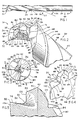
- FIG. 1 is a side view showing a drill bit embodying certain principles of the invention;
- FIG. 2 is a perspective view of a working end of a drill bit of FIG. 1 showing various surfaces and edges of the drill bit embodying certain principles of the invention;
- FIG. 3 is an end view of the working end of the drill bit of FIG. 2 showing a general arrangement of the surfaces and edges of the working end;
- FIG. 4 is a perspective view of the working end of the drill bit of FIG. 2 showing additional surfaces and edges of the working end embodying certain principles of the invention;
- FIG. 5 is a section view taken along line 5-5 of FIG. 3 and along a major cutting lip at the working end of the drill bit showing particularly the contour of portions of the cutting lip and certain other edges of the working end;
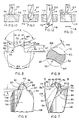
- FIG. 6 is a partial side view of the drill bit showing the working end in particular alignment;
- FIG. 7 is a partial side view of the drill bit showing the working end in an alignment which is rotated ninety degrees from the alignment shown in FIG. 6;
- FIG. 8 is a partial side view of the drill bit similar to FIG. 7 which illustrates a variety of significant parameters of the working end of the drill bit in accordance with certain principles of the invention'
- FIG. 9 is a section view taken along line 9-9 of FIG. 7 showing radial relief of a pilot tip of the working end in accordance with certain principles of the invention; and
- FIGS. 10 through 13 are partial side views showing the drill bit of FIG. 1 forming a hole in a workpiece.
- As illustrated in FIG. 1, a
stepped drill bit 20 for cutting a variety of materials such as metal, wood, plastics, laminates, piping and tubing is formed with anelongated drill body 22 having an elongated axis and which is composed of high speed steel.Drill body 22 is formed with ashank end 24, a workingend 26 and afluted section 28 interposed between the shank end and the working end. Shankend 24 includes around shank 30 which extends from the end ofdrill body 22 to one end offluted section 28. Workingend 26 includes a "fishtail"cutting section 32 of a major diameter and a pilottip cutting section 34 of a minor diameter which is smaller than the major diameter. Flutedsection 28 is formed with a pair ofhelical flutes 36 formed at a prescribed helix angle and which begin at the inward end ofshank 30 and extend to the outward end of workingend 26. - Referring to FIGS. 2 and 3, pilot
tip cutting section 34 ofdrill body 22 is formed with apilot tip 38 which is formed integrally with and extends a short distance axially beyond "fishtail"cutting 32. Further,pilot tip 38 is formed at its tip end with a conventional split point having spacedcutting edges -
Minor cutting lips pilot tip 38 withlip relief surfaces cutting edges cutting lips surfaces cutting edges Pilot tip 38 is formed with rounded outer surfaces 58 (FIG. 2) and 60 (FIG. 4) in an axial direction on opposite sides of the pilot tip. As viewed in FIG. 2outer surface 58 is formed with aforward edge 62 and atrailing edge 64. As illustrated in FIG. 4,outer surface 60 is formed with aforward edge 66 and atrailing edge 68. - Referring to FIGS. 2 and 4,
outer surfaces forward edges edges outer surfaces dashed line 70 as represented by radial relief "RR". In this manner, radial relief surfaces forforward edges outer surfaces - FIG. 8 is an outline of the profile of working
end 26 and illustrates various parameters ofdrill bit 20. As viewed in FIG. 8, each of theouter surfaces end 26 to the base ofpilot tip 38. - Referring to FIG. 2, "fishtail" cutting
section 32 is formed with a pair ofmajor cutting lips section 32 during the period when steep forward surfaces 54 and 56 are being formed onpilot tip 38. Formation ofshallow relief surfaces edges - During formation of various relief surfaces, each of the
major cutting lips end 26 as the lip approachespilot tip 38. For example, as more clearly shown in FIG. 4, cuttinglip 74 begins at anouter point 88 and progresses towardpilot tip 38. Betweenouter point 88 andpilot tip 38,lip 74 begins to curve toward the workingend 26 to eventually form a large radius at aforward edge 90 of afillet 92 where the lip merges withforward edge 66 ofouter surface 60 of the tip. This can be readily viewed in FIG. 5 wheretangent lines 94 illustrate the upwardly curving cuttinglip 74 andforward edge 66. Note that a portion of the cross-hatching in FIG. 5 has been removed to clearly revealtangent lines 94 and the manner in which cuttinglip 74 curves upwardly. - Referring to FIG. 2, cutting
lip 72 extends from anouter point 96 and eventually curves in an identical manner into a large radius at aforward edge 98 of afillet 100 where the lip merges withforward edge 62 ofouter surface 58 ofpilot tip 38. - Referring to FIGS. 2 and 4, each of the
fillets fillets corners fillets corners outer surfaces fillets drill body 22 to provide relief for forward edges 90 and 98, respectively. - Thus, continuous trailing relief is provided behind all forward working-engaging edges. For example, all surfaces of
drill body 22 which trail major cuttinglip 74, fillet forward edge 90 and pilot tipforward edge 66, are relieved in the manner described above so that, whendrill bit 20 is used to drill a hole in a workpiece, these trailing surfaces do not engage and rub against the walls of the hole. Similarly, all surfaces which trail cuttinglip 72, fillet forward edge 98 and pilot tip forward edge 62 are relieved as described so that, whendrill bit 20 is used to drill a hole in a workpiece, these trailing surfaces do not engage and rub against the walls of the hole. - Referring to FIGS. 1 and 2,
drill body 22 is formed withmargins 106 in a conventional manner onlands 108 of the drill body where the lands are contiguous withflute 36. - Referring to FIGS. 6, 8 and 9, working
end 26 is formed as illustrated with the various surfaces and cutting elements being dimensionally configured to produce the enhanceddrip bit 20 for superior performance in the formation of a hole in a workpiece. The parameters of the illustrated portions ofdrill bit 20 combine to provide for efficient cutting ability of the drill bit with superior relief from the cutting action to preclude any rubbing of the walls of the hole. - Referring to FIG. 8,
pilot tip 38 is formed with a point angle "TA" which, in the preferred embodiment, is 2.36 radians (135 degrees). The diameter "d" ofpilot tip 38 is thirty-seven percent of the major diameter "D" of thedrill body 22 while the height or length "L" of the pilot tip is seventy percent of the pilot tip diameter "d". For example, referring to the table of parameters below, a 1.27 cm (1/2 inch) drill bit will be formed with a pilot tip diameter of 0.4699 cm (0.185 inch) and a pilot tip length of 0.3276 cm (0.129 inch). Because of the small major diameter of the 0.3175 cm (1/8 inch) to 0.4762 cm (3/16 inch) drill bits, the pilot tip diameter "d" and pilot tip length "L" of these drill bits are based on larger percentage factors than the remaining drill bit sizes in the table.
- The radially inward back taper angle "BT" of
pilot tip 38 is 0.026 radian (one and one-half degrees) with a tolerance of plus or minus 0.009 radian (one-half degree). Referring to FIG. 9, the radial relief dimension "RR" at the trailingedges outer surfaces - Referring again to FIG. 8 the point angle "FA" of
major cutting lips major cutting lips - Referring to FIG. 1,
drill bit 20 is formed with a comparatively shallow or low helix angle "HA." In the preferred embodiment, the helix angle "HA" fordrill bit 20 is 0.393 radian (22.5 degrees) with a tolerance of plus or minus 0.026 radian (1.5 degrees). The shallow or low helix angle permitsdrill bit 20 to be used in drilling wood as well asa metal. Drill bits typically used for drilling in metal have higher helix angles. When metal-drilling drill bits are used for drilling wood, the higher helix angle causes the rotating bit to periodically enter an excessive self-feeding process whereafter the drill operator experiences a "jumping" sensation. With the low helix angle ofdrill bit 20, the operator experiences a smooth feed, particularly in wood, without excessive self feeding. - Further, when a drill bit breaks through the opposite side of a workpiece in the drilling of a hole, there is a tendency for the bit to begin to rapidly self-feed the bit through the drilled hole. This is particularly so for drill bits having high helix angles. With
drill bit 20 having a low helix angle, the undesirable self-feeding of the bit at breakthrough is reduced significantly. - As shown in FIGS. 10 and 11, the split point end of
pilot tip 38 is moved into aworkpiece 110 to form a centering orsecondary hole 112 which provides stabilization forbit 20 in the ultimate formation of the larger orprimary hole 114 by cuttinglips pilot tip 38 has all of the advantages of a split point tip which enhances centering of thebit 20 and provides a means for chip formation and removal particularly when compared to a conventional chisel edge which tends initially to work the immediate area of the workpiece and form an extrudate of the workpiece material rather than form chips. Further, a chisel edge tends to "skip" or "run" laterally on the workpiece surface, particularly if there is no center-punched hole to guide a chisel-edge bit. Therefore, the split-point end oftip 38 provides significant initial centering and stabilizing ofbit 20 in the drilling ofhole 114. - Further, if the drive unit or drill for rotating
drill bit 20 has a drill chuck which is out of round, thepilot tip 38 will wobble before the pilot tip engages theworkpiece 110. It would appear that the wobble ofdrill bit 20 would be transmitters in the formation of thehole 114 which would also be out of round. However, aspilot tip 38 entersworkpiece 110, the pilot tip immediately stabilizes workingend 26 ofdrill bit 20 to provide a stabilized formation ofholes - Once
pilot tip 38 becomes stabilized inworkpiece 110, there is no wobble in workingend 26 and inmajor cutting lips major cutting lips - Since
pilot tip 38 has stabilizeddrill bit 20, the pilot tip and thefishtail cutting section 32 will form a true round hole. Since there is no wobble in this area ofdrill bit 20, the corners ofpilot tip 38 andfishtail section 32 travel through the shortest distance necessary indrilling holes drill bit 20 when compared to a drill bit which is not stabilized wherein the points of such a drill bit must travel a greater distance to drill the same desired hole size which actually is drilled larger because of the out-of-round wobble effect. - Some drill bits are formed with a radially inward back taper on the lands and margins which begins at the working end of the bit and extends along the fluted section to the shank of the bit. Typically, drill bits have a back taper of 0.0020 cm per 2.54 cm (0.0008 inch per inch) of drill bit length. This taper provides relief from any wobble which may be experience along intermediate portions of the bit as the bit passes through the formed portions of the hole and which does not wobble beyond the established back taper. In the preferred embodiment of
drill bit 20, the radially inward back taper for thefluted section 28 is 0.00254 cm per 2.54 cm (0.001 inch per inch) of drill bit length with a tolerance of plus or minus 0.000254 cm (0.0001 inch). This further decreases any opportunity for wobble in an intermediate part of thedrill bit 20 to engage and rub against the walls of the formed portions ofhole 114. Effectively, then, lower power is required to movedrill bit 20 throughhole 114. - As illustrated in FIG. 3, a thickness "W" of a
web 116 ofdrill bit 20 is located where the wall of one of theflutes 36 is closest to the wall of the other flute. Drill bits with thick webs require significant thrust force or bias to move the drill bit through a workpiece because of the required drill chisel length. In the preferred embodiment of thedrill bit 20, the web has been designed with a relativelythin web 116 at the tip or workingend 26 of the bit. The thickness "W" ofweb 116 at the pilot ofbit 20 is approximately fifteen percent of the major drill diameter with a tolerance of plus or minus 0.0051 cm (0.002 inch). For example, as indicated in the above table of parameters, the web thickness at the pilot of the 0.4366 cm (11/64 inch) drill bit is 0.066 cm (0.026 inch) which is fifteen percent of the major drill diameter of 0.4366 cm (0.1719 inch). Also in the preferred embodiment ofdrill bit 20,web 116 increases in thickness from workingend 26 toward theshank 30 by a radially outward back taper of 0.061 cm (0.024 inch) per inch of drill bit length with a tolerance of plus or minus 0.0076 cm (0.003 inch). This taper permitsweb 116 to be thinner at the workingend 26, thereby reducing the thrust or bias requirement, while providing strengthening substance in trailing portions ofdrill bit 20. - Referring to FIG. 11, as
drill bit 20 is moved intoworkpiece 110,outer points 96 and 88 (Fig. 4) oflips section 22 to engage the workpiece and the outer points begin to cut a circular scribe in the workpiece. Eventually cuttinglips hole 112 formed bypilot tip 38 and the scribe formed bypoints drill bit 20 progresses throughworkpiece 110, the workingend 26 ofdrill bit 20 remains stabilized by the self-centering capability ofpilot tip 38. Further, points 96 and 88 of cuttinglips section 32 and are, therefore, cutting and forming a smooth-walled hole rather than a rough-burred hole of the type typically formed by most conventional twist drills. - Also, due to the various relief clearances and minimum web thickness on
pilot tip 38 and "fishtail" cuttingsection 32, continued drilling ofholes margins 106 and lands 108 in thefluted section 28. - Because
points section 32, a trepanning slug 118 (FIG. 12) is cut from the last portion of material of theworkpiece 110 in the formation of the hole. The trepanning effect results in the formation of a relatively burr-free opening at the bottom ofhole 114 compared to the typically burred-hole openings formed by conventional twist drills having point angles of less than 3.142 radians (180o). In addition, the low helix angle "HA" and the "fishtail" configuration of cuttingsection 32 preclude jamming and hang-up ofdrill bit 20 at the time when the bit "breaks through"workpiece 110 to form the lower opening ofhole 114. Sinceouter surfaces pilot tip 38 are formed with the radially inward back taper relief as indicated by angle "BT" (Fig. 8), and are formed with the radial relief represented by dimension "RR" (FIG. 9), forward edges 62 and 66 are the only portions of the pilot tip which tend to supporttrepanning plug 118 after the plug has been cut fromworkpiece 110. By virtue of the radii offillets drill bit 20 as illustrated in FIG. 13 and is not carried with the drill bit as the bit is withdrawn through newly formedhole 114. - When using a conventional chisel edge drill, a relatively large thrust force is required in order to move the drill through a workpiece. This is due, in part, to a back force which has to be overcome when the relatively long cutting lips of the conventional chisel edge drill cut into the workpiece.
- In comparison with the conventional chisel-edge drill, less thrust force is required when using
drill bit 20 because, in part, the effective combined length of cuttinglips drill bit 20 and thereby requires relatively less thrust force to be applied by an operator. This is a clear advantage ofdrill bit 20 over the conventional chisel-edge drill. - In summary,
drill bit 20 is designed to optimize use of a relatively low thrust or bias, for example low hand bias by an operator, to penetrate a workpiece comparatively faster than the drill bits. This minimises the time that drillbit 20 is working in the drilling of a hole thereby increasing the comparative life of the bit. The life ofdrill bit 20 is also increased by the formation of thick continuous chips which carry away heat from the work area and by a pilot tip design which eliminates transient edge loading as noted above. - The various design features also result in no stall at breakthrough and provide for an essentially burr-free, true-round hole having superior hole-wall finish.
- Thus,
drill bit 20 is geometrically designed to be self-centering, require low thrust, does not jam or form burrs at breakthrough, will not develop transient loading or wobble at workingend 26 which avoids breaking of corners, does not hang up while drilling, will penetrate the workpiece with ease, is less susceptible to breakage, will produce thicker chips for heat dispersal and full waste removal, will generate a balanced self-feeding capability to enhance the lower thrust characteristic, will develop a burr-free accurately-formed round hole and will provide comparatively longer drill life.
Claims (13)
- A drill bit for cutting accurately formed round holes through wood and metal having a step drill configuration and comprising an elongated drill body (22) having a shank end (24), an intermediate section (28) and a working end (26); the shank end (24), the intermediate section (28) and the working end (26) being all formed integrally in the drill body (22); flutes (36) formed in the drill body (22), each and every flute (36) having a continuous uninterrupted surface extending from a juncture of the shank end (24) and the intermediate section (28) to a free end tip (38) of the drill body (22) at the working end (26); the working end (26) of the drill body being formed with a first section (32) of a prescribed major drill diameter (D) and including major cutting lips (72, 74) for cutting a primary hole (114) through a workpiece (110); the working end (26) of the drill body (22) being formed with a second section (34) which is formed integrally with and extends from the first section (32) in a direction away from the shank end (24) of the drill body, said second section (34) having an outer surface (60, 58) with edges (62, 66) extending integrally from the inward ends of the major cutting lips (72, 74); the second section (34) of the drill body being formed with a minor drill diameter (d) smaller than the prescribed major drill diameter (D); characterized in that the second section (34) of the drill body is provided with a split point with minor cutting lips (46, 48) for cutting a secondary hole in the workpiece (110) preceding the cutting of the primary hole (114) and in that the major cutting lips (72, 74) are arranged in a "fishtail" configuration.
- A drill bit as claimed in Claim 1, characterized in that said split point has two cutting edges (40,42) which, in use, engage with workpiece (110) in advance of the engagement of the workpiece (110) by said minor cutting lips (46, 48) to initiate drilling by the drill bit (20), and said cutting edges (40, 42) are spaced apart but connect at the extreme tip of the split point cutting tip (38) by a slight chisel edge (44).
- A drill bit as claimed in Claim 1 or 2, characterized in that a fillet (92; 100) is formed at a juncture between said outer surface (60; 58) and said first section (32), said fillet (92; 100) raking radially inward to provide a relief clearance.
- A drill bit as claimed in Claim 3, characterized in that a forward edge (90; 98) of said fillet (92; 100) is contiguous with an associated one of said major cutting lips (74: 72), and said fillet (92; 100) is formed with a radius which decreases as said fillet (92; 100) extends away from said fillet forward edge (90; 98).
- A drill bit as claimed in Claim 3 or 4, characterized in that said second (34) has two diametrically opposed rounded outer surfaces (60, 58) which taper radially inwardly towards each other in the axial direction towards their respective fillets (92; 100) to provide an inward back taper (BT) of said second section (34).
- A drill bit as claimed in any preceding Claim, characterized in that said flutes (36) comprise a pair of diametrically opposed helical flutes (36) with a web (116) therebetween, and said web (116) has a radially outward taper beginning at the free end of said tip (38) and extending toward said shank end (24).
- A drill bit as claimed in any preceding Claim, characterized in that the lengthwise exterior of said drill body (22) is formed with a radially inward back taper from said major cutting lips (72, 74) toward said shank end (24).
- A drill bit as claimed in any preceding Claim, characterized in that said drill body (22) is formed with shallow lip relief surfaces (76,78) trailing major cutting lips (72,74).
- A drill bit as claimed in Claim 8, characterized in that said drill body (22) is formed with steep lip relief surfaces (80,82) trailing said shallow lip relief surfaces (76, 78).
- A self-centring drill bit as claimed in any preceding Claim, characterized in that said flutes (36) are formed helically in said drill body (22) at a helix angle of 22.5 degrees; said major cutting lips (72,74) are formed at a point angle of 190 degrees; said minor drill diameter (d) is thirty-seven percent of said prescribed major drill diameter (D); said second section (38) extends from the first section (32) in a direction away from the shank end (24) by a prescribed length which is seventy percent of the minor drill diameter (d); said split point is formed with a pair of minor cutting lips (46,48) at a point angle of 135 degrees, said second section (34) has rounded outer side surfaces (58,60) which taper toward the first section (32) at a back taper (BT) angle of one and one-half degrees; and said outer side surfaces (58,60) rake radially inwardly from a forward edge (62,66) thereof to form a second relief clearance (RR).
- A self-centring drill bit, as claimed in any preceding Claim, characterized in that said one outer surface (58,60) is integrally joined to the first section (32); and a fillet (92,100) is formed at a juncture of said outer surface (58,60) and the first section (32) which fillet (92,100) rakes radially inwardly as the fillet (92,100) extends away from a forward edge (62,66) of said outer surface (58,60) to provide a radial relief clearance (RR) on the fillet (92,100).
- A drill bit as claimed in Claim 11, characterized in that said fillet (92,100) comprises a radiused surface between a forward edge (90,98) and a trailing corner (102,104) thereof which is contiguous with and curves between said outer side surface (58,60) and a relief surface (76, 78) of a respective one of said major cutting lips (72,74), said radiused surface having a radius of curvature which decreases as the fillet (92, 100) extends away from said forward edge (90,98) to said trailing corner (102,104).
- A drill bit as claimed in any preceding Claim, characterized in that the radially outer surface (58, 60) of said second section (34) is substantially smooth.
Applications Claiming Priority (3)
| Application Number | Priority Date | Filing Date | Title |
|---|---|---|---|
| US897716 | 1986-08-18 | ||
| US06/897,716 US4968193A (en) | 1986-08-18 | 1986-08-18 | Self-centering drill bit with pilot tip |
| PCT/US1987/001913 WO1988001214A1 (en) | 1986-08-18 | 1987-08-06 | Self-centering drill bit with pilot tip |
Related Child Applications (1)
| Application Number | Title | Priority Date | Filing Date |
|---|---|---|---|
| EP94100974.8 Division-Into | 1994-01-24 |
Publications (2)
| Publication Number | Publication Date |
|---|---|
| EP0315643A1 EP0315643A1 (en) | 1989-05-17 |
| EP0315643B1 true EP0315643B1 (en) | 1995-01-18 |
Family
ID=25408304
Family Applications (1)
| Application Number | Title | Priority Date | Filing Date |
|---|---|---|---|
| EP87905400A Expired - Lifetime EP0315643B1 (en) | 1986-08-18 | 1987-08-06 | Self-centering drill bit with pilot tip |
Country Status (13)
| Country | Link |
|---|---|
| US (1) | US4968193A (en) |
| EP (1) | EP0315643B1 (en) |
| JP (1) | JPH01503693A (en) |
| KR (1) | KR940011919B1 (en) |
| AT (1) | ATE117228T1 (en) |
| AU (1) | AU626517B2 (en) |
| BR (1) | BR8707775A (en) |
| CA (1) | CA1298994C (en) |
| DE (1) | DE3751009T2 (en) |
| GB (1) | GB2193913B (en) |
| HK (2) | HK113494A (en) |
| SG (1) | SG26389G (en) |
| WO (1) | WO1988001214A1 (en) |
Families Citing this family (68)
| Publication number | Priority date | Publication date | Assignee | Title |
|---|---|---|---|---|
| US5288183A (en) * | 1986-08-18 | 1994-02-22 | Black & Decker Inc. | Self-centering drill bit with pilot tip |
| US5011342A (en) * | 1988-03-14 | 1991-04-30 | 501 Greenfield Industries, Inc. | Twist drill |
| US5056967A (en) * | 1989-03-28 | 1991-10-15 | Premier Industrial Corporation | Spotweld removal tool |
| US4997322A (en) * | 1989-12-26 | 1991-03-05 | Wells Bobby L | Automobile body reamer tool |
| US5401126A (en) * | 1991-01-17 | 1995-03-28 | Norris; Duane | Tool for removing end of cut-off pipe from a pipe coupling |
| US5149234A (en) * | 1991-08-16 | 1992-09-22 | Unibit Corporation | Spot-weld removing tool |
| US5244319A (en) * | 1991-11-01 | 1993-09-14 | Greenlee Textron Inc. | Auger bit |
| US5387059A (en) * | 1993-08-24 | 1995-02-07 | Borzemsky; George E. | Drill bit with improved stability |
| TW299385B (en) * | 1994-12-12 | 1997-03-01 | Black & Decker Inc | Cutting tools for drilling concrete, aggregate, masonry or the like materials |
| GB2303809A (en) * | 1995-07-29 | 1997-03-05 | Black & Decker Inc | Roll-forged drill bit |
| GB2303810A (en) * | 1995-07-29 | 1997-03-05 | Black & Decker Inc | Masonry drill bit |
| US5704745A (en) * | 1996-09-04 | 1998-01-06 | Credo Tool Company | Chuck sleeve insert for a drill |
| GB2318072A (en) * | 1996-09-21 | 1998-04-15 | Plansee Tizit Gmbh | Masonry bit |
| US5915485A (en) * | 1997-01-13 | 1999-06-29 | Mcatavey; Dennis B. | Ski post hole auger bit |
| US5931615A (en) * | 1997-04-03 | 1999-08-03 | Credo Tool Company | Twist drill bit |
| EP0893185B1 (en) * | 1997-05-29 | 2003-08-20 | Black & Decker Inc. | Twist drill |
| IL123858A (en) * | 1998-03-27 | 2003-05-29 | Iscar Ltd | Drilling head |
| DE29819388U1 (en) * | 1998-10-30 | 1999-09-02 | Keil Werkzeugfabrik Karl Eisch | Carbide insert for use on a drill |
| US6312432B1 (en) | 2000-03-02 | 2001-11-06 | Nemco Medical, Inc. | Bone drill |
| US6443674B1 (en) | 2000-05-19 | 2002-09-03 | Ics Cutting Tools, Inc. | Self-centering twist drill having a modified flat bottom section and a helical crown point tip |
| SE516229C2 (en) * | 2000-05-26 | 2001-12-03 | Eero Nygaard | drill point |
| US6652203B1 (en) | 2002-08-30 | 2003-11-25 | Credo Technology Corporation | Precision drill bits |
| US6848869B2 (en) * | 2002-10-07 | 2005-02-01 | Allied Machine & Engineering Corp. | Spot and chamfer drill insert |
| FR2850435B1 (en) * | 2003-01-29 | 2007-07-13 | Prospection & Inventions | ANCHORING ANKLE FOR FRIENDLY MATERIAL |
| US7832966B2 (en) * | 2003-01-30 | 2010-11-16 | Kennametal Inc. | Drill for making flat bottom hole |
| KR20040085381A (en) * | 2003-03-31 | 2004-10-08 | 한국항공우주산업 주식회사 | Hole Forming Drill |
| EP1512476B1 (en) * | 2003-09-08 | 2013-10-09 | Black & Decker Inc. | Self-centering drill bit with pilot tip |
| GB2405606A (en) * | 2003-09-08 | 2005-03-09 | Black & Decker Inc | Self-centering drill bit with pilot tip |
| US20050053439A1 (en) | 2003-09-09 | 2005-03-10 | Yuhong Wang | Two-flute twist drill |
| EP1687126B1 (en) * | 2003-11-17 | 2007-07-25 | Robert Bosch Gmbh | Drilling and/or chiselling tool |
| US7540696B1 (en) * | 2004-01-15 | 2009-06-02 | Century Tool & Design, Inc. | Spot drilling insert |
| DE102004026014B4 (en) * | 2004-05-27 | 2008-04-17 | Horst Miebach Gmbh | twist drill |
| US7237986B2 (en) * | 2004-08-09 | 2007-07-03 | Black & Decker Inc. | High speed metal drill bit |
| CN100368115C (en) * | 2005-04-10 | 2008-02-13 | 江苏飞达工具股份有限公司 | Method for improving service life of rolled spiral drill |
| KR100650314B1 (en) * | 2005-07-13 | 2006-11-27 | 주식회사 보광기계 | A screw drll bit of smelting furnace opening machine |
| GB2428611B (en) * | 2005-08-02 | 2007-10-03 | Dormer Tools | Twist drill |
| JP2007075959A (en) * | 2005-09-15 | 2007-03-29 | Honda Motor Co Ltd | Machining method and end mill |
| US8328477B2 (en) | 2006-03-02 | 2012-12-11 | Milwaukee Electric Tool Corporation | Cutting tool |
| CN101096056B (en) * | 2006-03-02 | 2013-06-19 | 密尔沃基电动工具公司 | Cutting tool |
| DE102006020538A1 (en) * | 2006-05-03 | 2007-11-15 | Irwin Industrial Tools Gmbh | Drilling head for drilling tool and drilling tool |
| US7708505B2 (en) * | 2006-10-06 | 2010-05-04 | Black & Decker Inc. | Joist drill |
| US20100003094A1 (en) * | 2007-01-09 | 2010-01-07 | Irwin Industrial Tool Company | Drill bit |
| US20080166194A1 (en) * | 2007-01-09 | 2008-07-10 | Durfee Laverne R | Drill bit |
| US20090000432A1 (en) * | 2007-06-28 | 2009-01-01 | Chen Bo-Shen | Tool Head Structure |
| FR2919212B1 (en) * | 2007-07-26 | 2009-12-25 | Snecma | CERAMIC DRILL FOR HIGH SPEED DRILLING OF COMPOSITE MATERIALS. |
| US7871224B2 (en) * | 2007-09-26 | 2011-01-18 | Robert Bosch Gmbh | Drill bit and reamer |
| US8070397B2 (en) * | 2008-02-19 | 2011-12-06 | Irwin Industrial Tool Company | Self feed bit |
| JP2011514263A (en) * | 2008-03-19 | 2011-05-06 | リー、シーチン | Spiral insertion byte |
| SE532432C2 (en) * | 2008-05-09 | 2010-01-19 | Sandvik Intellectual Property | Drill body with primary and secondary release surfaces |
| US8740515B2 (en) * | 2008-09-03 | 2014-06-03 | Black & Decker Inc. | Metal cutting drill bit |
| US20100307640A1 (en) * | 2009-06-03 | 2010-12-09 | Durfee La Verne R | Cutting edge and cutting tool |
| DE102010024391A1 (en) * | 2010-06-19 | 2011-12-22 | Tts Tooltechnic Systems Ag & Co. Kg | Wood drill, particularly for making deep holes in wood piece, has shaft extending along longitudinal axis for connecting to drill, where drilling head is arranged at shaft |
| EP2502709B1 (en) | 2011-03-22 | 2017-02-01 | Black & Decker Inc. | Chisels |
| WO2014015154A1 (en) | 2012-07-18 | 2014-01-23 | Milwaukee Electric Tool Corporation | Hole saw |
| US9500038B2 (en) | 2013-02-01 | 2016-11-22 | Milwaukee Electric Tool Corporation | Auger bit with replaceable cutting bit |
| US9333564B2 (en) | 2013-03-15 | 2016-05-10 | Black & Decker Inc. | Drill bit |
| USD737875S1 (en) | 2013-03-15 | 2015-09-01 | Black & Decker Inc. | Drill bit |
| USD734792S1 (en) | 2013-03-15 | 2015-07-21 | Black & Decker Inc. | Drill bit |
| EP2842673B1 (en) * | 2013-08-29 | 2018-11-21 | Black & Decker Inc. | Drill bit |
| DE102014204700B4 (en) * | 2014-03-13 | 2022-02-17 | Kennametal Inc. | Rotary tool, in particular drilling tool and method for producing a rotary tool |
| DE102014212714B4 (en) | 2014-07-01 | 2022-02-17 | Kennametal Inc. | drill head |
| US10507534B2 (en) | 2016-03-17 | 2019-12-17 | O-Tags, Inc. | Systems, methods, and apparatus for reliably installing survey tags |
| EP3251808A1 (en) * | 2016-06-01 | 2017-12-06 | Compass Corporation | Multi-blade type woodworking bit |
| WO2018021335A1 (en) * | 2016-07-26 | 2018-02-01 | 京セラ株式会社 | Cutting tool and method for manufacturing cut workpieces |
| CN209849949U (en) | 2018-01-29 | 2019-12-27 | 米沃奇电动工具公司 | Drill bit |
| CN216028284U (en) | 2018-07-10 | 2022-03-15 | 米沃奇电动工具公司 | Hole saw |
| CN209157232U (en) * | 2018-10-09 | 2019-07-26 | 米沃奇电动工具公司 | Drill bit |
| USD958855S1 (en) | 2019-12-09 | 2022-07-26 | Milwaukee Electric Tool Corporation | Hole saw |
Family Cites Families (33)
| Publication number | Priority date | Publication date | Assignee | Title |
|---|---|---|---|---|
| US546041A (en) * | 1895-09-10 | Twist-drill | ||
| US2193186A (en) * | 1938-06-06 | 1940-03-12 | Herbert G Hard | Twist drill |
| US2332295A (en) * | 1941-11-07 | 1943-10-19 | Western Electric Co | Drill |
| US2600286A (en) * | 1947-09-08 | 1952-06-10 | Bell Machine Company | Drill bit |
| GB653193A (en) * | 1948-07-07 | 1951-05-09 | Ernest Henry Evans | Renewing ball-float valve seats |
| US2652083A (en) * | 1951-08-02 | 1953-09-15 | Cleveland Twist Drill Co | Wood bit |
| CH299798A (en) * | 1952-05-21 | 1954-06-30 | Vogt Walter | Forest. |
| US2866302A (en) * | 1955-06-16 | 1958-12-30 | Christen & Co A G | Machine for sharpening drills |
| US2778252A (en) * | 1956-09-26 | 1957-01-22 | Nat Twist Drill & Tool Company | Self-thinned heavy-duty twist drill structure |
| US2903922A (en) * | 1957-06-24 | 1959-09-15 | Cincinnati Milling Machine Co | Self-centering drill |
| DE1107114B (en) * | 1958-01-24 | 1961-05-18 | Cawi & Co G M B H | Machine for grinding the cutting edges of a drill, countersink, step drill or the like. |
| GB937767A (en) * | 1960-09-30 | 1963-09-25 | Koenigsee Werkzeugfabrik | Improvements in or relating to cutting tools |
| US3237488A (en) * | 1963-10-04 | 1966-03-01 | Pratt & Whitney Inc | Drill |
| US3592555A (en) * | 1969-05-02 | 1971-07-13 | Radial Lip Machine Corp | Drill with discontinuous cutting lips |
| GB1368270A (en) * | 1971-12-29 | 1974-09-25 | Vorabbi L | Combined drilling and reaming tool |
| US3779664A (en) * | 1971-12-30 | 1973-12-18 | Boeing Co | Drill with guide tip |
| DE2261846A1 (en) * | 1972-12-18 | 1974-06-20 | Hilti Ag | FASTENING OF PANEL-SHAPED INSULATING MATERIAL |
| US3920350A (en) * | 1974-02-11 | 1975-11-18 | Stanley Works | Spade bit |
| US4080093A (en) * | 1974-11-18 | 1978-03-21 | Hartmetallwerkzeugfabrik Andreas Maier Kg | Drill for electronic conductor plates |
| CA1097104A (en) * | 1978-02-23 | 1981-03-10 | Keith Siddall | Drills |
| US4209275A (en) * | 1978-10-30 | 1980-06-24 | Kim Joo B | Twist drill |
| AU528398B2 (en) * | 1979-01-23 | 1983-04-28 | Somta Tools (Proprietary) Limited | Drills |
| IT1130119B (en) * | 1980-04-16 | 1986-06-11 | Aeritalia Spa | PROCEDURE FOR MAKING HOLES OF A PRE-FIXED DIAMETER ON A COMPOUND OF OVERLAPPING SHEETS INCLUDING AT LEAST ONE SHEET OF AN AGGLOMERATE OF CARBON OR GLASS FIBERS, A STEEL SHEET AND A TITANIUM SHEET |
| DE3131794C2 (en) * | 1980-08-29 | 1986-08-07 | Toshiaki Osaka Hosoi | drill |
| US4330229A (en) * | 1980-12-04 | 1982-05-18 | Omark Industries, Inc. | Drill bit |
| DE3123048C2 (en) * | 1981-02-12 | 1983-06-16 | Paul 5630 Remscheid Schmitz | Twist drill |
| EP0088037A1 (en) * | 1982-02-24 | 1983-09-07 | Hughes Tool Company | Single pass drill |
| US4605347A (en) * | 1982-12-27 | 1986-08-12 | Lockheed Missiles & Space Company, Inc. | High speed drill reamer |
| DE8303526U1 (en) * | 1983-02-09 | 1983-06-30 | Schmitz, Paul, 5630 Remscheid | SPIRAL DRILL |
| DE3316193A1 (en) * | 1983-05-04 | 1984-11-08 | Haberer und Hirt Hydraulik-Service und Werkzeuge GmbH, 7623 Schenkenzell | Removal of a first metal sheet secured to a second metal sheet by spot welding |
| DE8328538U1 (en) * | 1983-10-04 | 1983-12-29 | Rolf Klenk Hartmetallwerkzeugfabrik GmbH & Co KG, 7959 Balzheim | FULL CARBIDE SPIRAL DRILLS FOR MACHINING HEAVY MACHINING MATERIALS |
| US4556347A (en) * | 1984-05-11 | 1985-12-03 | Lockheed Corporation | Split-point twist drill |
| SU1238905A1 (en) * | 1984-09-12 | 1986-06-23 | Харьковский Ордена Ленина Политехнический Институт Им.В.И.Ленина | Drill for working composition polymer materials |
-
1986
- 1986-08-18 US US06/897,716 patent/US4968193A/en not_active Expired - Lifetime
-
1987
- 1987-08-06 BR BR8707775A patent/BR8707775A/en not_active IP Right Cessation
- 1987-08-06 AT AT87905400T patent/ATE117228T1/en not_active IP Right Cessation
- 1987-08-06 JP JP62504842A patent/JPH01503693A/en active Pending
- 1987-08-06 SG SG1995905519A patent/SG26389G/en unknown
- 1987-08-06 WO PCT/US1987/001913 patent/WO1988001214A1/en active IP Right Grant
- 1987-08-06 KR KR1019880700352A patent/KR940011919B1/en not_active IP Right Cessation
- 1987-08-06 DE DE3751009T patent/DE3751009T2/en not_active Expired - Lifetime
- 1987-08-06 EP EP87905400A patent/EP0315643B1/en not_active Expired - Lifetime
- 1987-08-06 AU AU78018/87A patent/AU626517B2/en not_active Ceased
- 1987-08-17 CA CA000544728A patent/CA1298994C/en not_active Expired - Fee Related
- 1987-08-18 GB GB8719459A patent/GB2193913B/en not_active Expired - Fee Related
-
1994
- 1994-10-20 HK HK113494A patent/HK113494A/en not_active IP Right Cessation
-
1995
- 1995-04-06 HK HK50195A patent/HK50195A/en not_active IP Right Cessation
Also Published As
| Publication number | Publication date |
|---|---|
| KR880701602A (en) | 1988-11-04 |
| EP0315643A1 (en) | 1989-05-17 |
| KR940011919B1 (en) | 1994-12-27 |
| GB8719459D0 (en) | 1987-09-23 |
| GB2193913B (en) | 1990-05-16 |
| AU7801887A (en) | 1988-03-08 |
| ATE117228T1 (en) | 1995-02-15 |
| DE3751009D1 (en) | 1995-03-02 |
| SG26389G (en) | 1995-09-01 |
| HK50195A (en) | 1995-04-13 |
| DE3751009T2 (en) | 1995-05-18 |
| HK113494A (en) | 1994-10-27 |
| BR8707775A (en) | 1989-08-15 |
| AU626517B2 (en) | 1992-08-06 |
| GB2193913A (en) | 1988-02-24 |
| JPH01503693A (en) | 1989-12-14 |
| CA1298994C (en) | 1992-04-21 |
| WO1988001214A1 (en) | 1988-02-25 |
| US4968193A (en) | 1990-11-06 |
Similar Documents
| Publication | Publication Date | Title |
|---|---|---|
| EP0315643B1 (en) | Self-centering drill bit with pilot tip | |
| US5288183A (en) | Self-centering drill bit with pilot tip | |
| US7267514B2 (en) | Self-centering drill bit with pilot tip | |
| US7520703B2 (en) | Twist drill with a pilot tip | |
| US5312208A (en) | Burnishing drill | |
| US4536107A (en) | Drill bit | |
| US7832966B2 (en) | Drill for making flat bottom hole | |
| US6739809B2 (en) | Cutting point for a drill | |
| US4274771A (en) | Boring reamer with end mill cutters | |
| US20040076483A1 (en) | Stepped drill bit having split tip | |
| US5636948A (en) | Drill for synthetic fiber filled plastic and like materials | |
| US7140815B2 (en) | Drill for making flat bottom hole | |
| US2859645A (en) | Drilling bit for construction work | |
| EP1782901A2 (en) | Hole saw having a drill bit | |
| KR20010080356A (en) | Cutting tool for machining bores in materials having spring-back | |
| CA2647787C (en) | Drill insert geometry having v-notched web | |
| US4620822A (en) | Flat bottom hole drill | |
| US4449865A (en) | Method and tool for generating countersunk holes in composite materials | |
| US6231281B1 (en) | Thread milling cutter with drilling edges | |
| US5112167A (en) | High speed burnishing drill | |
| JPH0258042B2 (en) | ||
| JPH11245119A (en) | Drill tap | |
| KR101822517B1 (en) | Step drill bit | |
| GB2405607A (en) | Self centering drill bit with pilot tip | |
| CN218964134U (en) | Deep hole processing drill |
Legal Events
| Date | Code | Title | Description |
|---|---|---|---|
| PUAI | Public reference made under article 153(3) epc to a published international application that has entered the european phase |
Free format text: ORIGINAL CODE: 0009012 |
|
| 17P | Request for examination filed |
Effective date: 19890114 |
|
| AK | Designated contracting states |
Kind code of ref document: A1 Designated state(s): AT BE CH DE FR GB IT LI LU NL SE |
|
| 17Q | First examination report despatched |
Effective date: 19891004 |
|
| GRAA | (expected) grant |
Free format text: ORIGINAL CODE: 0009210 |
|
| AK | Designated contracting states |
Kind code of ref document: B1 Designated state(s): AT BE CH DE FR GB IT LI LU NL SE |
|
| REF | Corresponds to: |
Ref document number: 117228 Country of ref document: AT Date of ref document: 19950215 Kind code of ref document: T |
|
| XX | Miscellaneous (additional remarks) |
Free format text: TEILANMELDUNG 94100974.8 EINGEREICHT AM 06/08/87. |
|
| REF | Corresponds to: |
Ref document number: 3751009 Country of ref document: DE Date of ref document: 19950302 |
|
| ITF | It: translation for a ep patent filed |
Owner name: GUZZI E RAVIZZA S.R.L. |
|
| ET | Fr: translation filed | ||
| PLBE | No opposition filed within time limit |
Free format text: ORIGINAL CODE: 0009261 |
|
| STAA | Information on the status of an ep patent application or granted ep patent |
Free format text: STATUS: NO OPPOSITION FILED WITHIN TIME LIMIT |
|
| 26N | No opposition filed | ||
| PGFP | Annual fee paid to national office [announced via postgrant information from national office to epo] |
Ref country code: SE Payment date: 20010719 Year of fee payment: 15 |
|
| PGFP | Annual fee paid to national office [announced via postgrant information from national office to epo] |
Ref country code: LU Payment date: 20010725 Year of fee payment: 15 |
|
| PGFP | Annual fee paid to national office [announced via postgrant information from national office to epo] |
Ref country code: BE Payment date: 20010810 Year of fee payment: 15 |
|
| REG | Reference to a national code |
Ref country code: GB Ref legal event code: IF02 |
|
| PG25 | Lapsed in a contracting state [announced via postgrant information from national office to epo] |
Ref country code: LU Free format text: LAPSE BECAUSE OF NON-PAYMENT OF DUE FEES Effective date: 20020806 |
|
| PG25 | Lapsed in a contracting state [announced via postgrant information from national office to epo] |
Ref country code: SE Free format text: LAPSE BECAUSE OF NON-PAYMENT OF DUE FEES Effective date: 20020807 |
|
| PG25 | Lapsed in a contracting state [announced via postgrant information from national office to epo] |
Ref country code: BE Free format text: LAPSE BECAUSE OF NON-PAYMENT OF DUE FEES Effective date: 20020831 |
|
| BERE | Be: lapsed |
Owner name: *BLACK & DECKER INC. Effective date: 20020831 |
|
| EUG | Se: european patent has lapsed | ||
| PGFP | Annual fee paid to national office [announced via postgrant information from national office to epo] |
Ref country code: NL Payment date: 20040716 Year of fee payment: 18 |
|
| PGFP | Annual fee paid to national office [announced via postgrant information from national office to epo] |
Ref country code: AT Payment date: 20040721 Year of fee payment: 18 |
|
| PGFP | Annual fee paid to national office [announced via postgrant information from national office to epo] |
Ref country code: GB Payment date: 20040728 Year of fee payment: 18 |
|
| PGFP | Annual fee paid to national office [announced via postgrant information from national office to epo] |
Ref country code: FR Payment date: 20040819 Year of fee payment: 18 |
|
| PG25 | Lapsed in a contracting state [announced via postgrant information from national office to epo] |
Ref country code: IT Free format text: LAPSE BECAUSE OF NON-PAYMENT OF DUE FEES;WARNING: LAPSES OF ITALIAN PATENTS WITH EFFECTIVE DATE BEFORE 2007 MAY HAVE OCCURRED AT ANY TIME BEFORE 2007. THE CORRECT EFFECTIVE DATE MAY BE DIFFERENT FROM THE ONE RECORDED. Effective date: 20050806 Ref country code: GB Free format text: LAPSE BECAUSE OF NON-PAYMENT OF DUE FEES Effective date: 20050806 Ref country code: AT Free format text: LAPSE BECAUSE OF NON-PAYMENT OF DUE FEES Effective date: 20050806 |
|
| APAH | Appeal reference modified |
Free format text: ORIGINAL CODE: EPIDOSCREFNO |
|
| PG25 | Lapsed in a contracting state [announced via postgrant information from national office to epo] |
Ref country code: NL Free format text: LAPSE BECAUSE OF NON-PAYMENT OF DUE FEES Effective date: 20060301 |
|
| GBPC | Gb: european patent ceased through non-payment of renewal fee |
Effective date: 20050806 |
|
| PG25 | Lapsed in a contracting state [announced via postgrant information from national office to epo] |
Ref country code: FR Free format text: LAPSE BECAUSE OF NON-PAYMENT OF DUE FEES Effective date: 20060428 |
|
| NLV4 | Nl: lapsed or anulled due to non-payment of the annual fee |
Effective date: 20060301 |
|
| REG | Reference to a national code |
Ref country code: FR Ref legal event code: ST Effective date: 20060428 |
|
| PGFP | Annual fee paid to national office [announced via postgrant information from national office to epo] |
Ref country code: CH Payment date: 20060829 Year of fee payment: 20 |
|
| PGFP | Annual fee paid to national office [announced via postgrant information from national office to epo] |
Ref country code: DE Payment date: 20061002 Year of fee payment: 20 |
|
| REG | Reference to a national code |
Ref country code: CH Ref legal event code: PL |