EP0315207A2 - A system and method for automatically controlling a vehicle speed to a desired cruise speed with a release function - Google Patents
A system and method for automatically controlling a vehicle speed to a desired cruise speed with a release function Download PDFInfo
- Publication number
- EP0315207A2 EP0315207A2 EP88118447A EP88118447A EP0315207A2 EP 0315207 A2 EP0315207 A2 EP 0315207A2 EP 88118447 A EP88118447 A EP 88118447A EP 88118447 A EP88118447 A EP 88118447A EP 0315207 A2 EP0315207 A2 EP 0315207A2
- Authority
- EP
- European Patent Office
- Prior art keywords
- vehicle speed
- speed
- cruise
- signal
- circuit
- Prior art date
- Legal status (The legal status is an assumption and is not a legal conclusion. Google has not performed a legal analysis and makes no representation as to the accuracy of the status listed.)
- Granted
Links
Images


Classifications
-
- B—PERFORMING OPERATIONS; TRANSPORTING
- B60—VEHICLES IN GENERAL
- B60K—ARRANGEMENT OR MOUNTING OF PROPULSION UNITS OR OF TRANSMISSIONS IN VEHICLES; ARRANGEMENT OR MOUNTING OF PLURAL DIVERSE PRIME-MOVERS IN VEHICLES; AUXILIARY DRIVES FOR VEHICLES; INSTRUMENTATION OR DASHBOARDS FOR VEHICLES; ARRANGEMENTS IN CONNECTION WITH COOLING, AIR INTAKE, GAS EXHAUST OR FUEL SUPPLY OF PROPULSION UNITS IN VEHICLES
- B60K31/00—Vehicle fittings, acting on a single sub-unit only, for automatically controlling vehicle speed, i.e. preventing speed from exceeding an arbitrarily established velocity or maintaining speed at a particular velocity, as selected by the vehicle operator
- B60K31/06—Vehicle fittings, acting on a single sub-unit only, for automatically controlling vehicle speed, i.e. preventing speed from exceeding an arbitrarily established velocity or maintaining speed at a particular velocity, as selected by the vehicle operator including fluid pressure actuated servomechanism in which the vehicle velocity affecting element is actuated by fluid pressure
- B60K31/10—Vehicle fittings, acting on a single sub-unit only, for automatically controlling vehicle speed, i.e. preventing speed from exceeding an arbitrarily established velocity or maintaining speed at a particular velocity, as selected by the vehicle operator including fluid pressure actuated servomechanism in which the vehicle velocity affecting element is actuated by fluid pressure and means for comparing one electrical quantity, e.g. voltage, pulse, waveform, flux, or the like, with another quantity of a like kind, which comparison means is involved in the development of a pressure which is fed into the controlling means
- B60K31/102—Vehicle fittings, acting on a single sub-unit only, for automatically controlling vehicle speed, i.e. preventing speed from exceeding an arbitrarily established velocity or maintaining speed at a particular velocity, as selected by the vehicle operator including fluid pressure actuated servomechanism in which the vehicle velocity affecting element is actuated by fluid pressure and means for comparing one electrical quantity, e.g. voltage, pulse, waveform, flux, or the like, with another quantity of a like kind, which comparison means is involved in the development of a pressure which is fed into the controlling means where at least one electrical quantity is set by the vehicle operator
- B60K31/105—Vehicle fittings, acting on a single sub-unit only, for automatically controlling vehicle speed, i.e. preventing speed from exceeding an arbitrarily established velocity or maintaining speed at a particular velocity, as selected by the vehicle operator including fluid pressure actuated servomechanism in which the vehicle velocity affecting element is actuated by fluid pressure and means for comparing one electrical quantity, e.g. voltage, pulse, waveform, flux, or the like, with another quantity of a like kind, which comparison means is involved in the development of a pressure which is fed into the controlling means where at least one electrical quantity is set by the vehicle operator in a memory, e.g. a capacitor
- B60K31/107—Vehicle fittings, acting on a single sub-unit only, for automatically controlling vehicle speed, i.e. preventing speed from exceeding an arbitrarily established velocity or maintaining speed at a particular velocity, as selected by the vehicle operator including fluid pressure actuated servomechanism in which the vehicle velocity affecting element is actuated by fluid pressure and means for comparing one electrical quantity, e.g. voltage, pulse, waveform, flux, or the like, with another quantity of a like kind, which comparison means is involved in the development of a pressure which is fed into the controlling means where at least one electrical quantity is set by the vehicle operator in a memory, e.g. a capacitor the memory being digital
Definitions
- the present invention relates generally to a system and method for automatically controlling a vehicle speed to a desired cruise speed applicable to a vehicle.
- ASCD Automatic Speed Control
- the automatic speed controlling function described above is released when the driver actuates a clutch pedal or brake pedal.
- the vehicle speed can exceed the set cruising speed .
- the accelerator pedal depression is halted, the vehicle can again run at the set cruise speed after the speed reduction caused by an engine brake.
- a microcomputer is installed which controls a throttle valve actuator according to a vehicle speed difference between the actual vehicle speed and set vehicle speed in the above-described vehicle speed controlling system. An opening angle of a throttle valve is adjusted through the actuation of the throttle actuator. Controlling means constituted by the microcomputer inhibits a power supply to the throttle actuator when the actual vehicle speed is a vehicle speed inappropriate for the cruising speed (for example, 45 Km/h or below) since it is uncontrollable speed.
- controlling means described above often errorneously detects the vehicle speed which is below the lowest controllable speed as the controllable vehicle speed so that inappropriate control over the throttle actuator is resulted.
- means for determining the vehicle speed is provided in addition to controlling means for controlling an actuator actuating a throttle valve of a vehicular engine so that the vehicle speed coincides with a target vehicle speed at which the vehicle cruises. Therefore, when the vehicle speed determining means determines that the vehicle speed is below a predetermined value, the power supply to the actuator is interrupted.
- a system for automatically controlling a vehicle speed to a desired cruise speed comprising: (a) first means for detecting the vehicle speed and outputting a signal indicative thereof; (b) second means through which the current vehicle speed is set as the cruise speed; (c) third means responsive to the set through the second means for receiving the vehicle speed signal from the first means and for actuating an engine speed adjusting mechanism installed in a vehicular engine so that the vehicle speed coincides with the set cruise speed; (d) fourth means for determining whether the vehicle speed detected by the first means exceeds a lowest speed limit value above which the third means becomes effective; and (e) fifth means for interrupting the cruise control carried out by means of the third means on the basis of the result of determination by the fourth means.
- a system for automatically controlling a vehicle speed to a desired cruise speed comprising: (a) first means for detecting the vehicle speed and outputting a signal indicative thereof; (b) second means through which the current vehicle speed is set as the cruise speed; (c) third means responsive to the set through the second means for receiving the vehicle speed signal and for actuating en engine speed adjusting mechanism installed in a vehicular engine so that the vehicle speed coincides with the set cruise speed; (d) fourth means for determining whether the vehicle speed detected by the first means falls in an effective operation range of the third means; (e) fifth means for determining whether an electric field around a periphery of the third means falls in the effective operation range of the third means; and (f) sixth means for interrupting the cruise control through the engine speed adjusting mechanism by means of the third means on the basis of the result of determination at least one of the fourth and fifth means.
- the above-described object can also be achieved by providing a method for automatically controlling a vehicle speed to a desired cruise speed, comprising the steps of: (a) detecting the vehicle speed and outputting a signal indicative thereof; (b) providing a set switch through which the vehicle speed is set as the cruise speed and setting the switch; (c) controlling a variable of an engine speed adjusting mechanism installed in a vehicular engine so that the vehicle speed coincides with the set cruise speed; (d) determining whether the vehicle speed exceeds a lowest speed limit above which the cruise control carried out in the step (c) becomes effective; and (e) cancelling the cruise control carried out in the step (c) on the basis of the result of the determination carried out in the step (d).
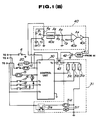
- Fig. 1 is an electrical circuit of a system for automatically controlling a vehicle speed to a desired cruise speed according to the present invention.
- a DC power supply (battery) denoted by 1 is connected between a horn 7 and ground.
- a switch 2 called an ignition switch is connected between a positive pole of the battery 1 and a fuse 3.
- a horn relay 5 connected to a horn switch 6 is connected between the positive pole of the battery 1 and horn 7.
- Numeral 8 denotes a cruising main switch which can be placed on an ON position or on an OFF position.
- Numeral 9 denotes a cruise relay connected in series with the ignition switch 2 via the fuse 3.
- the main switch 8 is a self-holding switch which is self-held by means of the cruising relay 9 and is installed on a part of an instrument panel (not shown ).
- Numeral 10 denotes a main lamp which illuminates when the main switch 8 is turned on.
- a normally closed clutch switch 11 is connected to the self-holding relay 9 and is open when a clutch of a vehicular transmission is depressed and a normally closed brake switch 12 is connected to the clutch switch 11 and is open when a brake pedal is depressed. These clutch and brake switches are connected to an input terminal T1 of a control unit 30. It is noted that a cut relay and inhibitor switch are connected in series in place of the brake and clutch switches 11 and 12 in the case of an equipment of an automatic transmission on the vehicle.
- a stop lamp 16 which illuminates when a stop lamp switch 15 is turned on upon a depression of the brake pedal.
- a set/coast switch 17 which is turned on when the vehicle speed is set as the cruising speed and the set vehicle speed is reduced during the cruising run is connected to an input terminal T2 of the control unit 30.
- Numeral 19 denotes a cancel switch which is turned on when the driver has an intention to release forcibly the cruising mode therethrough. It is noted that these switches are installed on a part of a steering wheel. One contact of each switch 17, 18, and 19 is connected to either of the input terminals T2 and T3 of the control unit 30.
- Numeral 20 denotes a vehicle speed sensor outputting the vehicle speed signal and which is connected to the control unit 30.
- the control unit 30 includes a microcomputer which receives on and off signals from the various switches, discriminates various conditions on the basis of such on and off signals, and controls an actuator 31 enclosed with a dot line, for actuating a throttle valve provided in the vehicular engine.
- the actuator 31 is of a positive pressure type adjusting an opening angle of the throttle valve using a compressed air, comprising a release valve 31a for discharging the compressed air from a compressed air tank to the atmosphere, an air valve 31b for opening the compressed air to the atmosphere, and an air supply valve 31c for supplying the compressed air.
- a throttle wire connected to a diaphragm actuated by these valves causes control for the opening angle of the throttle valve.
- a tank for reserving the compressed air is installed as a drive source of the actuator 31.
- a pressure switch 31d is installed in the tank which is turned on when the compressed air pressure exceeds a constant value.
- a vehicle speed determining circuit 40 is connected to the vehicle speed sensor 20.
- the vehicle speed determining circuit 40 is installed independently of the control unit 30.
- An output signal of the vehicle speed determining circuit 40 is supplied to an AND circuit 41.
- a transistor 42 with its bias circuit (not shown) is connected to an output end of the AND circuit 41.
- a relay having a normally open contact 43 is connected between an input terminal T5 of the control unit 30 and actuator 31. The relay 43 supplies the power to the actuator 31 when the transistor 42 is conducted and a magnet portion thereof is energized.
- a base of a transistor T r is connected with a resistor R1 and a capacitor C1 for eliminating noise and the output end of the vehicle speed sensor 20 to receive an analog quantity indicating the vehicle speed information.
- a collector of the transistor T r is connected to a constant voltage (e.g., dc 5 volts) supply circuit (not shown) provided in the control unit 30 via a resistor R2.
- a pulse signal A1 having a rectangular shape and a period corresponding to the vehicle speed is supplied to a monostable multivibrator 40a. The pulse signal A1 is generated in response to an intermittent signal derived from the vehicle speed sensor 20 by means of the transistor T r .
- the monostable multivibrator 40a is connected to an inverting input terminal of a comparator 40b via a resistor R3 and a capacitor C2.
- the multivibrator 40a produces a rectangular pulse signal A2 having a pulsewidth of T as shown in Figs. 2 and 3 in accordance with the input signal A1 at each rising edge of the input signal A1.
- the pulse signal A2 is smoothed by means of the resistor R3 and the capacitor C2 so that an average voltage signal A3 of the pulse train signal A2 is supplied to the inverting input terminal of the comparator 40b.
- V L of the voltage signal A3 will be described with reference to Fig. 2.
- V L 5 x T x f L , wherein f L denotes an inverted number of the pulse period of the pulse signal A1 ,i.e., the frequency of the pulse signal A1 when the vehicle speed V is below the predetermined vehicle speed V TH .
- V H 5 x T x f H
- f H denotes the inverted number of the pulse signal period, i.e., the frequency of the pulse signal A1 when the vehicle speed V is above the predetermined speed V TH .
- the value of the voltage signal A3 becomes reduced. As the vehicle speed increases, the value of the voltage signal A3 is also increased. It is noted that the value of the predetermined speed V TH is set with the speed below which the cruising speed is not appropriate to be taken into consideration.
- a non-inverting input terminal of the comparator receives a reference voltage signal V o .
- the value of the reference voltage signal V o is set as follows. V L ⁇ V o ⁇ V H
- V L denotes the value of the voltage signal A3 when the vehicle cruises at a low speed
- V H denotes the other value of the voltage signal A3 when the vehicle cruises at a high speed.
- the comparator 40b when the value of the voltage signal A3 is below the reference voltage signal V o , the comparator 40b outputs a high level signal A4. When the value of the voltage signal exceeds the reference voltage signal V o , the comparator 40b outputs a low level signal A4 The output signal of the comparator 40b is supplied to an inverter 40c and the one input terminal of the AND circuit 41. Hence, the low level signal is supplied to the AND circuit 41 when the vehicle speed is low and the high level signal is supplied to the AND circuit 41 when the vehicle speed is high.
- An output signal of an electric field intensity determining circuit 44 shown in Fig. 4 is supplied to the other input terminal of the AND circuit 41.
- an electric field intensity measuring circuit 47 measures an induced voltage of a loop coil 46 wound around a harness 45 extended about a connector part of the control unit as shown in Fig. 4. The measured voltage value is checked to determine whether it is above a predetermined voltage value by means of an electric field intensity determining circuit 44. If the measured voltage value is above the predetermined value (strong electric field), the L level signal is supplied to the AND circuit 41. If the measured voltage value is below the predetermined volt value, the H level signal is supplied to the AND circuit 41.
- the AND circuit 41 outputs the H level signal so that the transistor 42 is conducted and the relay 43 is turned on to supply the power to the actuator 31.
- the cruising relay 9 is energized and is held in the ON position so that the main lamp 10 is illuminated. Then the input terminals T1 and T4 of the control unit receive the power supply voltage from the battery 1.
- the input terminal T1 of the control unit 30 is connected to the output terminal T5 via a normally open contact of a relay, a coil thereof receiving the power supply by means of a switching transistor conducted upon receipt of an ON signal from the microcomputer.
- the microcomputer does not output to the above-described switching transistor so that the input terminal T1 is not connected to the output terminal T5.
- the control unit 30 errorneously detects the vehicle speed so that the input terminal T1 is connected to the output terminal T5, the power supply to the actuator 31 cannot be carried out since the relay 43 remains off.
- the vehicle speed determining circuit 40 calculates the vehicle speed V on the basis of the vehicle speed indicative signal from the vehicle speed sensor 20 in terms of an analog quantity and determines that the calculated vehicle speed is below the predetermined vehicle speed V TH , the L level signal is outputted to the AND circuit 41, thus the output signal of the AND circuit 41 indicating the L level.
- the transistor 42 is not conducting so that the relay 43 remains off.
- the microcomputer issues the instruction so that the input terminal T1 is connected to the output terminal T5.
- the vehicle speed determining circuit 40 outputs the H level signal to the AND circuit 41. If the electric field intensity is below the predetermined value, the electric field intensity determining circuit 44 outputs the H level signal.
- the AND circuit 41 outputs the H level signal so that the transistor 42 is conducting so that the relay 43 is turned on to supply the power to the actuator 31. It is noted that when the electric field intensity determining circuit 44 determines the electric field intensity and outputs the L level signal, the power supply to the actuator 31 is interrupted.
- the control unit 30 After the relay 43 is turned on and the vehicle speed reaches a desired vehicle speed, the driver can freely depress the set/cruise switch 17.
- the control unit 30 stores the set vehicle speed and compares the actual vehicle speed signal outputted from the vehicle speed sensor with the set vehicle speed. Then, the control unit 30 controls according to, e.g., the difference therebetween the open and close of the release valve 31a, the air valve 31b, and supply valve 31c. That is to say, when the vehicle speed is above the set vehicle speed, the control unit 30 closes the release valve 31a, opens the air valve 31b, and closes the supply valve 31c, thus the throttle valve being directed toward the close position.
- the control unit 30 closes the release valve 31a, the air valve 31b, and opens the supply valve 31c, thus the throttle valve being directed toward the open position. In this way, the opening angle of the throttle valve being adjusted so that the engine revolution is controlled so that the vehicle speed settles the set vehicle speed.
- the driver depresses the clutch pedal or brake pedal.
- the clutch switch 11 or brake switch 12 is open so that the supply of the power to the input terminal T1 of the control unit 30 is interrupted so that the actuator 31 receives no power supply.
- the cruise control is also interrupted. The same interruption of the cruise control is carried out by the turn off of the cruise main switch 8.
- a cancel switch 19 is provided which is turned on so that the input terminals T2 and T3 receive simultaneously the power supply voltage, thus stopping the vehicle speed control operation.
- the driver During the cruise control, if the driver continues to depress the accelerator switch 18 to increase the set vehicle speed and the vehicle speed reaches the new desired vehicle speed, the driver releases the switch 18. At this time, the vehicle speed is set to the new desired vehicle speed. If the driver continuous to depress the set/cruise switch 17 to decrease set vehicle speed during the cruise control, the vehicle speed is decreased due to the engine braking. When the vehicle speed reaches the new desired vehicle speed, the driver releases the set/cruise switch 17 so that the vehicle speed is settled to the new set vehicle speed.
- analog vehicle speed determining circuit 40 is used as the vehicle speed determining means, such a switch as shown in Fig. 5 may be utilized.
- the switch including a movable contact 52 having a constant length and which is extended on a part of a peripheral edge of an insulating disc plate 51 rotating with a pointer 50 of a speedometer and a fixed contact 53 fixed on a speedometer side surface is connected between the output terminal T5 of the control unit 30 and the actuator 31.
- the movable contact 52 is not contacted with the fixed contact 53 so that no power supply is received by the actuator 31.
- the insulating disc plate 51 rotates in a clockwise direction as viewed from Fig. 5.
- the movable contact 52 When the vehicle speed exceeds the predetermined value (for example, 45 Km/h), the movable contact 52 is contacted with the fixed contact 53 so that the actuator 31 receives the power supply. In this way, when the vehicle speed is below the predetermined value, the contacts 52, 53 do not contact with each other so that the power supply to the actuator 31 is interrupted.
- the predetermined value for example, 45 Km/h
- the vehicle speed determining means since in the automatic vehicle speed controlling system and method according to the present invention the vehicle speed determining means is provided in addition to the controlling means for the actuator, the vehicle speed determining means causes the interruption of the power supply to the actuator upon the determination that the vehicle speed is below the predetermined vehicle speed (lower limit speed). Consequently, when the vehicle speed is below the predetermined speed, the cruising control operation can more positively be interrupted without failure.
Abstract
Description
- The present invention relates generally to a system and method for automatically controlling a vehicle speed to a desired cruise speed applicable to a vehicle.
- Recently, vehicle speed automatically controlling systems have been installed in vehicles by means of which the vehicles automatically run at desired cruising speeds (so called ASCD (Automatic Speed Control) Devices).
- In such vehicles, operators (drivers) accelerate the vehicles to reach speeds at which the drivers desire the vehicles to cruise. When the vehicles become run at the desired speeds, the drivers recognize that the vehicles run at the desired cruising speeds through speedometers and the drivers set the vehicle speeds through set buttons. At this time, the systems adjust opening angles of throttle valves or carburetors so that the actual vehicle speeds coincide with the set vehicle speeds.
- One of such vehicle speed automatically controlling systems as described above is exemplified by a Japanese Patent Application First Publication (Tokkai) sho 59-58134 published on April 3, 1984.
- When such vehicle speed automatically controlling systems are installed in the vehicles, it is convenient for the driver since no depression on an accelerator pedal is needed to cruise the vehicle during run on a freeway.
- Furthermore, the automatic speed controlling function described above is released when the driver actuates a clutch pedal or brake pedal. In addition, when the accelerator pedal is depressed, the vehicle speed can exceed the set cruising speed . When the accelerator pedal depression is halted, the vehicle can again run at the set cruise speed after the speed reduction caused by an engine brake.
- A microcomputer is installed which controls a throttle valve actuator according to a vehicle speed difference between the actual vehicle speed and set vehicle speed in the above-described vehicle speed controlling system. An opening angle of a throttle valve is adjusted through the actuation of the throttle actuator. Controlling means constituted by the microcomputer inhibits a power supply to the throttle actuator when the actual vehicle speed is a vehicle speed inappropriate for the cruising speed (for example, 45 Km/h or below) since it is uncontrollable speed.
- However, the controlling means described above often errorneously detects the vehicle speed which is below the lowest controllable speed as the controllable vehicle speed so that inappropriate control over the throttle actuator is resulted.
- It is therefore an object of the present invention to provide a system and method for automatically controlling a vehicle speed to a desired cruising speed in which when the vehicle speed is below a predetermined value, the function of the automatic speed controlling can positively be released.
- According to one aspect of the present invention, means for determining the vehicle speed is provided in addition to controlling means for controlling an actuator actuating a throttle valve of a vehicular engine so that the vehicle speed coincides with a target vehicle speed at which the vehicle cruises. Therefore, when the vehicle speed determining means determines that the vehicle speed is below a predetermined value, the power supply to the actuator is interrupted.
- The above-described object can be achieved by providing a system for automatically controlling a vehicle speed to a desired cruise speed, comprising: (a) first means for detecting the vehicle speed and outputting a signal indicative thereof; (b) second means through which the current vehicle speed is set as the cruise speed; (c) third means responsive to the set through the second means for receiving the vehicle speed signal from the first means and for actuating an engine speed adjusting mechanism installed in a vehicular engine so that the vehicle speed coincides with the set cruise speed; (d) fourth means for determining whether the vehicle speed detected by the first means exceeds a lowest speed limit value above which the third means becomes effective; and (e) fifth means for interrupting the cruise control carried out by means of the third means on the basis of the result of determination by the fourth means.
- The above-described object can also be achieved by providing a system for automatically controlling a vehicle speed to a desired cruise speed, comprising: (a) first means for detecting the vehicle speed and outputting a signal indicative thereof; (b) second means through which the current vehicle speed is set as the cruise speed; (c) third means responsive to the set through the second means for receiving the vehicle speed signal and for actuating en engine speed adjusting mechanism installed in a vehicular engine so that the vehicle speed coincides with the set cruise speed; (d) fourth means for determining whether the vehicle speed detected by the first means falls in an effective operation range of the third means; (e) fifth means for determining whether an electric field around a periphery of the third means falls in the effective operation range of the third means; and (f) sixth means for interrupting the cruise control through the engine speed adjusting mechanism by means of the third means on the basis of the result of determination at least one of the fourth and fifth means.
- The above-described object can also be achieved by providing a method for automatically controlling a vehicle speed to a desired cruise speed, comprising the steps of: (a) detecting the vehicle speed and outputting a signal indicative thereof; (b) providing a set switch through which the vehicle speed is set as the cruise speed and setting the switch; (c) controlling a variable of an engine speed adjusting mechanism installed in a vehicular engine so that the vehicle speed coincides with the set cruise speed; (d) determining whether the vehicle speed exceeds a lowest speed limit above which the cruise control carried out in the step (c) becomes effective; and (e) cancelling the cruise control carried out in the step (c) on the basis of the result of the determination carried out in the step (d).
- Figs. 1 (A) and 1 (B) are integrally a schematic circuit wiring diagram of a system for automatically controlling a vehicle speed to a desired cruising speed in a preferred embodiment according to the present invention.
- Figs. 2 and 3 are signal waveform charts of a vehicle speed determining circuit shown in Fig. 1 (B).
- Fig. 4 is a schematic circuit block diagram of an electric field detecting apparatus.
- Fig. 5 is a schematic connection diagram of another preferred embodiment according to the present invention.
- Reference will hereinafter be made to the drawings in order to facilitate understanding of the present invention.
- Fig. 1 is an electrical circuit of a system for automatically controlling a vehicle speed to a desired cruise speed according to the present invention.
- In Fig. 1, a DC power supply (battery) denoted by 1 is connected between a
horn 7 and ground. Aswitch 2 called an ignition switch is connected between a positive pole of thebattery 1 and afuse 3. Ahorn relay 5 connected to ahorn switch 6 is connected between the positive pole of thebattery 1 andhorn 7. When thehorn switch 6 is turned on, thehorn 7 is sounded. Numeral 8 denotes a cruising main switch which can be placed on an ON position or on an OFF position. Numeral 9 denotes a cruise relay connected in series with theignition switch 2 via thefuse 3. Themain switch 8 is a self-holding switch which is self-held by means of thecruising relay 9 and is installed on a part of an instrument panel (not shown ). Numeral 10 denotes a main lamp which illuminates when themain switch 8 is turned on. - A normally closed
clutch switch 11 is connected to the self-holding relay 9 and is open when a clutch of a vehicular transmission is depressed and a normally closedbrake switch 12 is connected to theclutch switch 11 and is open when a brake pedal is depressed. These clutch and brake switches are connected to an input terminal T₁ of acontrol unit 30. It is noted that a cut relay and inhibitor switch are connected in series in place of the brake andclutch switches - Furthermore, a
stop lamp 16 which illuminates when astop lamp switch 15 is turned on upon a depression of the brake pedal. - A set/
coast switch 17 which is turned on when the vehicle speed is set as the cruising speed and the set vehicle speed is reduced during the cruising run is connected to an input terminal T₂ of thecontrol unit 30. Numeral 19 denotes a cancel switch which is turned on when the driver has an intention to release forcibly the cruising mode therethrough. It is noted that these switches are installed on a part of a steering wheel. One contact of eachswitch control unit 30. Numeral 20 denotes a vehicle speed sensor outputting the vehicle speed signal and which is connected to thecontrol unit 30. - The
control unit 30 includes a microcomputer which receives on and off signals from the various switches, discriminates various conditions on the basis of such on and off signals, and controls anactuator 31 enclosed with a dot line, for actuating a throttle valve provided in the vehicular engine. - The
actuator 31 is of a positive pressure type adjusting an opening angle of the throttle valve using a compressed air, comprising a release valve 31a for discharging the compressed air from a compressed air tank to the atmosphere, an air valve 31b for opening the compressed air to the atmosphere, and an air supply valve 31c for supplying the compressed air. A throttle wire connected to a diaphragm actuated by these valves causes control for the opening angle of the throttle valve. A tank for reserving the compressed air is installed as a drive source of theactuator 31. A pressure switch 31d is installed in the tank which is turned on when the compressed air pressure exceeds a constant value. When the pressure switch 31d is turned on, a motor relay 31e is energized so that its normally closed contact is open so as to interrupt the power supply to amotor 31f. Thus, the operation of the compressor is halted, thus halting the increase in the compressed air tank. In this way, the air pressure in the compressed air is held constant. - The construction of the automatically vehicle speed controlling system is exemplified by Unites States Patent Applications Serial No. 169,218 filed on March 16, 1988, Serial No. 130,473 filed on December 9, 1987, and Serial No. 146,558 filed on January 21, 1988, the disclosures of which are hereby incorporated by reference.
- A vehicle
speed determining circuit 40 is connected to thevehicle speed sensor 20. The vehiclespeed determining circuit 40 is installed independently of thecontrol unit 30. An output signal of the vehiclespeed determining circuit 40 is supplied to anAND circuit 41. Atransistor 42 with its bias circuit (not shown) is connected to an output end of theAND circuit 41. A relay having a normallyopen contact 43 is connected between an input terminal T₅ of thecontrol unit 30 andactuator 31. Therelay 43 supplies the power to theactuator 31 when thetransistor 42 is conducted and a magnet portion thereof is energized. - The detailed construction of the vehicle
speed determining circuit 40 will be described below. - A base of a transistor Tr is connected with a resistor R₁ and a capacitor C₁ for eliminating noise and the output end of the
vehicle speed sensor 20 to receive an analog quantity indicating the vehicle speed information. A collector of the transistor Tr is connected to a constant voltage (e.g.,dc 5 volts) supply circuit (not shown) provided in thecontrol unit 30 via a resistor R₂. A pulse signal A₁ having a rectangular shape and a period corresponding to the vehicle speed is supplied to a monostable multivibrator 40a. The pulse signal A₁ is generated in response to an intermittent signal derived from thevehicle speed sensor 20 by means of the transistor Tr. The monostable multivibrator 40a is connected to an inverting input terminal of acomparator 40b via a resistor R₃ and a capacitor C₂. The multivibrator 40a produces a rectangular pulse signal A₂ having a pulsewidth of T as shown in Figs. 2 and 3 in accordance with the input signal A₁ at each rising edge of the input signal A₁. - The pulse signal A₂ is smoothed by means of the resistor R₃ and the capacitor C₂ so that an average voltage signal A₃ of the pulse train signal A₂ is supplied to the inverting input terminal of the
comparator 40b. - In a case when the vehicle speed V is below a predetermined speed VTH (for example, 45 Km/h), a value VL of the voltage signal A₃ will be described with reference to Fig. 2.
- The value VL is expressed as follows.
VL = 5 x T x fL,
, wherein fL denotes an inverted number of the pulse period of the pulse signal A₁ ,i.e., the frequency of the pulse signal A₁ when the vehicle speed V is below the predetermined vehicle speed VTH. - Similarly, when the vehicle speed V is above the predetermined vehicle speed VTH, the value VH of the voltage signal A₃ is expressed below.
VH = 5 x T x fH,
wherein fH denotes the inverted number of the pulse signal period, i.e., the frequency of the pulse signal A₁ when the vehicle speed V is above the predetermined speed VTH. - Since the frequency of the pulse signal A₁ becomes large as the vehicle speed increases, the value of the voltage signal A₃ becomes reduced. As the vehicle speed increases, the value of the voltage signal A₃ is also increased. It is noted that the value of the predetermined speed VTH is set with the speed below which the cruising speed is not appropriate to be taken into consideration.
- In addition, a non-inverting input terminal of the comparator receives a reference voltage signal Vo. The value of the reference voltage signal Vo is set as follows.
VL < Vo < VH - In the above inequalities, VL denotes the value of the voltage signal A₃ when the vehicle cruises at a low speed and VH denotes the other value of the voltage signal A₃ when the vehicle cruises at a high speed.
- Therefore, when the value of the voltage signal A₃ is below the reference voltage signal Vo, the
comparator 40b outputs a high level signal A₄. When the value of the voltage signal exceeds the reference voltage signal Vo, thecomparator 40b outputs a low level signal A₄ The output signal of thecomparator 40b is supplied to an inverter 40c and the one input terminal of the ANDcircuit 41. Hence, the low level signal is supplied to the ANDcircuit 41 when the vehicle speed is low and the high level signal is supplied to the ANDcircuit 41 when the vehicle speed is high. - An output signal of an electric field
intensity determining circuit 44 shown in Fig. 4 is supplied to the other input terminal of the ANDcircuit 41. Although a protective circuit is provided adjacent to thecontrol unit 30 against a strong electric field intensity, thecontrol unit 30 may often errorneously operate if the control unit is exposed to a strong electric field exceeding a dielectric strength of the protective circuit. Therefore, an electric fieldintensity measuring circuit 47 measures an induced voltage of aloop coil 46 wound around aharness 45 extended about a connector part of the control unit as shown in Fig. 4. The measured voltage value is checked to determine whether it is above a predetermined voltage value by means of an electric fieldintensity determining circuit 44. If the measured voltage value is above the predetermined value (strong electric field), the L level signal is supplied to the ANDcircuit 41. If the measured voltage value is below the predetermined volt value, the H level signal is supplied to the ANDcircuit 41. - Consequently, if both output signals of the vehicle
speed determining circuit 40 and electric fieldintensity determining circuit 44 are at the H level, the ANDcircuit 41 outputs the H level signal so that thetransistor 42 is conducted and therelay 43 is turned on to supply the power to theactuator 31. - Next, the operation of the preferred embodiment shown in Figs. 1 to 4 will be described below.
- First, when the
main switch 8 is turned on with theignition switch 2 turned on, the cruisingrelay 9 is energized and is held in the ON position so that themain lamp 10 is illuminated. Then the input terminals T₁ and T₄ of the control unit receive the power supply voltage from thebattery 1. - The operation of the preferred embodiment in a case when the vehicle runs at a low speed, i.e., the vehicle speed V is below the predetermined speed VTH will be described below.
- During such a low speed as described above, the power supply is not supplied to the output terminal T₅ due to an issue of an instruction from the microcomputer of the
control unit 30. Consequently, theactuator 31 is not operated. - That is to say, although not shown in the drawings, the input terminal T₁ of the
control unit 30 is connected to the output terminal T₅ via a normally open contact of a relay, a coil thereof receiving the power supply by means of a switching transistor conducted upon receipt of an ON signal from the microcomputer. However, when the actual vehicle speed calculated on the basis of the signal derived from thevehicle speed sensor 20 is below VTH, the microcomputer does not output to the above-described switching transistor so that the input terminal T₁ is not connected to the output terminal T₅. - However, even if the
control unit 30 errorneously detects the vehicle speed so that the input terminal T₁ is connected to the output terminal T₅, the power supply to theactuator 31 cannot be carried out since therelay 43 remains off. In details, When the vehiclespeed determining circuit 40 calculates the vehicle speed V on the basis of the vehicle speed indicative signal from thevehicle speed sensor 20 in terms of an analog quantity and determines that the calculated vehicle speed is below the predetermined vehicle speed VTH, the L level signal is outputted to the ANDcircuit 41, thus the output signal of the ANDcircuit 41 indicating the L level. Thus, thetransistor 42 is not conducting so that therelay 43 remains off. - Next, when the vehicle speed V is above the predetermined vehicle speed VTH, the microcomputer issues the instruction so that the input terminal T₁ is connected to the output terminal T₅. The vehicle
speed determining circuit 40, at the same time, outputs the H level signal to the ANDcircuit 41. If the electric field intensity is below the predetermined value, the electric fieldintensity determining circuit 44 outputs the H level signal. Thus, the ANDcircuit 41 outputs the H level signal so that thetransistor 42 is conducting so that therelay 43 is turned on to supply the power to theactuator 31. It is noted that when the electric fieldintensity determining circuit 44 determines the electric field intensity and outputs the L level signal, the power supply to theactuator 31 is interrupted. - After the
relay 43 is turned on and the vehicle speed reaches a desired vehicle speed, the driver can freely depress the set/cruise switch 17. When the set/cruise switch 17 is depressed, thecontrol unit 30 stores the set vehicle speed and compares the actual vehicle speed signal outputted from the vehicle speed sensor with the set vehicle speed. Then, thecontrol unit 30 controls according to, e.g., the difference therebetween the open and close of the release valve 31a, the air valve 31b, and supply valve 31c. That is to say, when the vehicle speed is above the set vehicle speed, thecontrol unit 30 closes the release valve 31a, opens the air valve 31b, and closes the supply valve 31c, thus the throttle valve being directed toward the close position. When the vehicle speed is below the set vehicle speed, thecontrol unit 30 closes the release valve 31a, the air valve 31b, and opens the supply valve 31c, thus the throttle valve being directed toward the open position. In this way, the opening angle of the throttle valve being adjusted so that the engine revolution is controlled so that the vehicle speed settles the set vehicle speed. - During the cruise control described above, the driver depresses the clutch pedal or brake pedal. At this time, the
clutch switch 11 orbrake switch 12 is open so that the supply of the power to the input terminal T₁ of thecontrol unit 30 is interrupted so that theactuator 31 receives no power supply. Thus, the cruise control is also interrupted. The same interruption of the cruise control is carried out by the turn off of the cruisemain switch 8. - On the either hand, a cancel
switch 19 is provided which is turned on so that the input terminals T₂ and T₃ receive simultaneously the power supply voltage, thus stopping the vehicle speed control operation. - During the cruise control, if the driver continues to depress the
accelerator switch 18 to increase the set vehicle speed and the vehicle speed reaches the new desired vehicle speed, the driver releases theswitch 18. At this time, the vehicle speed is set to the new desired vehicle speed. If the driver continuous to depress the set/cruise switch 17 to decrease set vehicle speed during the cruise control, the vehicle speed is decreased due to the engine braking. When the vehicle speed reaches the new desired vehicle speed, the driver releases the set/cruise switch 17 so that the vehicle speed is settled to the new set vehicle speed. - Although in the above-described preferred embodiment the analog vehicle
speed determining circuit 40 is used as the vehicle speed determining means, such a switch as shown in Fig. 5 may be utilized. - In details, the switch including a
movable contact 52 having a constant length and which is extended on a part of a peripheral edge of an insulatingdisc plate 51 rotating with apointer 50 of a speedometer and a fixedcontact 53 fixed on a speedometer side surface is connected between the output terminal T₅ of thecontrol unit 30 and theactuator 31. When the vehicle stops or the vehicle speed is below the predetermined vehicle speed, themovable contact 52 is not contacted with the fixedcontact 53 so that no power supply is received by theactuator 31. However, when the vehicle speed increases, the insulatingdisc plate 51 rotates in a clockwise direction as viewed from Fig. 5. When the vehicle speed exceeds the predetermined value (for example, 45 Km/h), themovable contact 52 is contacted with the fixedcontact 53 so that theactuator 31 receives the power supply. In this way, when the vehicle speed is below the predetermined value, thecontacts actuator 31 is interrupted. - As described hereinabove, since in the automatic vehicle speed controlling system and method according to the present invention the vehicle speed determining means is provided in addition to the controlling means for the actuator, the vehicle speed determining means causes the interruption of the power supply to the actuator upon the determination that the vehicle speed is below the predetermined vehicle speed (lower limit speed). Consequently, when the vehicle speed is below the predetermined speed, the cruising control operation can more positively be interrupted without failure.
- It will fully be appreciated by those skilled in the art that the foregoing description is made in terms of the preferred embodiments and various changes and modifications may be made without departing from the scope of the present invention which is to be defined by the appended claims.
Claims (11)
Applications Claiming Priority (3)
| Application Number | Priority Date | Filing Date | Title |
|---|---|---|---|
| JP62279133A JPH01122735A (en) | 1987-11-06 | 1987-11-06 | Constant speed running device |
| JP279133/87 | 1987-11-06 | ||
| JP27913387 | 1987-11-06 |
Publications (4)
| Publication Number | Publication Date |
|---|---|
| EP0315207A2 true EP0315207A2 (en) | 1989-05-10 |
| EP0315207A3 EP0315207A3 (en) | 1989-09-13 |
| EP0315207B1 EP0315207B1 (en) | 1993-10-27 |
| EP0315207B2 EP0315207B2 (en) | 2000-04-05 |
Family
ID=17606893
Family Applications (1)
| Application Number | Title | Priority Date | Filing Date |
|---|---|---|---|
| EP88118447A Expired - Lifetime EP0315207B2 (en) | 1987-11-06 | 1988-11-04 | A system and method for automatically controlling a vehicle speed to a desired cruise speed with a release function |
Country Status (4)
| Country | Link |
|---|---|
| US (1) | US5127487A (en) |
| EP (1) | EP0315207B2 (en) |
| JP (1) | JPH01122735A (en) |
| DE (1) | DE3885233T3 (en) |
Families Citing this family (23)
| Publication number | Priority date | Publication date | Assignee | Title |
|---|---|---|---|---|
| JPH031833U (en) * | 1989-05-29 | 1991-01-10 | ||
| US10361802B1 (en) | 1999-02-01 | 2019-07-23 | Blanding Hovenweep, Llc | Adaptive pattern recognition based control system and method |
| US8352400B2 (en) | 1991-12-23 | 2013-01-08 | Hoffberg Steven M | Adaptive pattern recognition based controller apparatus and method and human-factored interface therefore |
| JPH05201269A (en) * | 1992-01-29 | 1993-08-10 | Mitsubishi Electric Corp | Constant speed travel device for vehicle |
| JPH06144077A (en) * | 1992-11-11 | 1994-05-24 | Jidosha Denki Kogyo Co Ltd | Control method of automatic constant speed traveling device |
| JPH06144080A (en) * | 1992-11-12 | 1994-05-24 | Jidosha Denki Kogyo Co Ltd | Control method of automatic constant speed traveling device |
| JPH079883A (en) * | 1993-06-24 | 1995-01-13 | Jidosha Denki Kogyo Co Ltd | Automatic constant-speed travel device |
| GB2295695B (en) * | 1994-12-01 | 1999-01-20 | Lucas Ind Plc | Cruise control system for a road vehicle |
| JP3478107B2 (en) | 1998-01-14 | 2003-12-15 | 日産自動車株式会社 | Travel control device for vehicles |
| US7904187B2 (en) | 1999-02-01 | 2011-03-08 | Hoffberg Steven M | Internet appliance system and method |
| CN1098176C (en) * | 1999-05-07 | 2003-01-08 | 光阳工业股份有限公司 | Control method and equipment for limiting speed of motorcycle |
| US6836238B1 (en) * | 2001-10-09 | 2004-12-28 | Escort Inc. | Police radar/laser detector with integral vehicle parameter display using a vehicle interface |
| US6614385B2 (en) | 1999-06-14 | 2003-09-02 | Escort Inc. | Police activity transponder utilizing a vehicle interface |
| AU5874300A (en) * | 1999-06-14 | 2001-01-02 | Escort Inc. | Radar warning receiver with position and velocity sensitive functions |
| US8525723B2 (en) * | 1999-06-14 | 2013-09-03 | Escort Inc. | Radar detector with navigation function |
| DE19956457A1 (en) * | 1999-11-24 | 2001-05-31 | Volkswagen Ag | Memory circuit for electric vehicle controllers is automatically holding electromagnetic circuit connected to engine controller, can pass binary electrical operating parameter to controller |
| US7804440B1 (en) | 2007-01-05 | 2010-09-28 | Escort Inc. | Radar detector with position and velocity sensitive functions |
| US7576679B1 (en) * | 2007-01-05 | 2009-08-18 | Escort Inc. | Radar detector with position and velocity sensitive functions |
| US8373588B2 (en) | 2009-02-20 | 2013-02-12 | Escort Inc. | Wireless connectivity in a radar detector |
| US8624771B2 (en) * | 2009-02-20 | 2014-01-07 | Escort Inc. | Wireless connectivity in a radar detector |
| US9656671B2 (en) * | 2014-08-25 | 2017-05-23 | Ford Global Technologies, Llc | Coast switch for an electrified vehicle |
| CN104912676A (en) * | 2015-06-17 | 2015-09-16 | 东风商用车有限公司 | Brake priority control system for commercial vehicle |
| US11634130B2 (en) * | 2020-03-26 | 2023-04-25 | Robert Bosch Gmbh | Adapting an advanced driver assistance system of a vehicle |
Citations (4)
| Publication number | Priority date | Publication date | Assignee | Title |
|---|---|---|---|---|
| JPS5958134A (en) | 1982-09-24 | 1984-04-03 | Aisin Seiki Co Ltd | Constant speed traveling device for car |
| US4908764A (en) | 1987-01-23 | 1990-03-13 | Nissan Motor Company, Ltd. | System and method for automatically controlling a vehicle speed to a desired cruising speed |
| US4914595A (en) | 1987-03-19 | 1990-04-03 | Nissan Motor Company, Limited | System and method for automatically controlling vehicle speed to a desired cruising speed |
| US4922428A (en) | 1986-12-10 | 1990-05-01 | Nissan Motor Company, Limited | System and method for automatically controlling cruising speed of vehicles |
Family Cites Families (11)
| Publication number | Priority date | Publication date | Assignee | Title |
|---|---|---|---|---|
| US3635306A (en) * | 1970-01-08 | 1972-01-18 | Gen Motors Corp | Vehicle speed indicator and controller |
| FR2309365A1 (en) * | 1975-04-28 | 1976-11-26 | Hemmert Jean | Automatic car speed limiter - has speedometer electrical contacts with adjustable setting controlling variable length piston assembly in accelerator linkage |
| US4336566A (en) * | 1979-08-03 | 1982-06-22 | Associated Engineering Limited | Vehicle speed control systems |
| JPS5815730A (en) * | 1981-07-21 | 1983-01-29 | Nippon Denso Co Ltd | Speed controller for vehicle |
| FR2512264A1 (en) * | 1981-08-26 | 1983-03-04 | Merlin Gerin | COMPENSATED HYBRID CURRENT SENSOR |
| JPS6056637A (en) * | 1983-09-06 | 1985-04-02 | Aisin Seiki Co Ltd | Car-speed controller |
| GB2152166A (en) * | 1983-12-06 | 1985-07-31 | Ae Plc | Automatic vehicle speed control |
| JPS6144033A (en) * | 1984-08-08 | 1986-03-03 | Toyota Motor Corp | Constant speed travelling device |
| JPH08510B2 (en) * | 1986-05-01 | 1996-01-10 | 日産自動車株式会社 | Vehicle speed automatic control method and device |
| JPH0712804B2 (en) * | 1986-06-03 | 1995-02-15 | 日産自動車株式会社 | Vehicle constant-speed traveling device |
| JPH07108622B2 (en) * | 1986-08-28 | 1995-11-22 | 日産自動車株式会社 | Vehicle constant-speed traveling device |
-
1987
- 1987-11-06 JP JP62279133A patent/JPH01122735A/en active Pending
-
1988
- 1988-10-27 US US07/263,783 patent/US5127487A/en not_active Expired - Lifetime
- 1988-11-04 DE DE3885233T patent/DE3885233T3/en not_active Expired - Lifetime
- 1988-11-04 EP EP88118447A patent/EP0315207B2/en not_active Expired - Lifetime
Patent Citations (4)
| Publication number | Priority date | Publication date | Assignee | Title |
|---|---|---|---|---|
| JPS5958134A (en) | 1982-09-24 | 1984-04-03 | Aisin Seiki Co Ltd | Constant speed traveling device for car |
| US4922428A (en) | 1986-12-10 | 1990-05-01 | Nissan Motor Company, Limited | System and method for automatically controlling cruising speed of vehicles |
| US4908764A (en) | 1987-01-23 | 1990-03-13 | Nissan Motor Company, Ltd. | System and method for automatically controlling a vehicle speed to a desired cruising speed |
| US4914595A (en) | 1987-03-19 | 1990-04-03 | Nissan Motor Company, Limited | System and method for automatically controlling vehicle speed to a desired cruising speed |
Also Published As
| Publication number | Publication date |
|---|---|
| DE3885233T3 (en) | 2000-12-21 |
| US5127487A (en) | 1992-07-07 |
| DE3885233D1 (en) | 1993-12-02 |
| EP0315207B1 (en) | 1993-10-27 |
| EP0315207A3 (en) | 1989-09-13 |
| JPH01122735A (en) | 1989-05-16 |
| EP0315207B2 (en) | 2000-04-05 |
| DE3885233T2 (en) | 1994-05-11 |
Similar Documents
| Publication | Publication Date | Title |
|---|---|---|
| US5127487A (en) | System and method for automatically controlling a vehicle speed to a desired cruise speed with a release function | |
| US6360158B1 (en) | Intelligent cruise control device | |
| US6012780A (en) | Brake controller for trailer brakes | |
| US5109819A (en) | Accelerator control system for a motor vehicle | |
| US4894652A (en) | Vehicle brakelights activating device | |
| GB2310731A (en) | Control of the approach of a vehicle to an obstruction | |
| US4352403A (en) | Vehicle speed control system | |
| US5411452A (en) | Running control apparatus for motor vehicle | |
| GB2284028A (en) | Parking aid with brake intervention | |
| US20060152350A1 (en) | Method and device for notifying the driver of a motor vehicle | |
| EP0036753B1 (en) | Overspeed engine control | |
| US6622071B2 (en) | Acceleration monitoring method for a longitudinal dynamics open-loop or closed-loop controller in motor vehicles | |
| EP0335333A2 (en) | System and method for controlling vehicle speed to cruise at desired speed for vehicle | |
| KR20010022822A (en) | Process and system for controlling the speed of a vehicle | |
| US4914595A (en) | System and method for automatically controlling vehicle speed to a desired cruising speed | |
| US5434786A (en) | Vehicle speed controlling apparatus and method for controlling speed of vehicle with automatic transmission | |
| US5040121A (en) | System and method for automatically controlling vehicle speed to desired cruise speed | |
| JPS60135330A (en) | Detector of holding state of steering wheel | |
| US5025379A (en) | System and method for automatically controlling vehicle speed to desired cruise speed using microcomputer | |
| US5064015A (en) | System and method for automatically controlling vehicle speed to a desired cruise speed | |
| WO1992007729A1 (en) | Engine electronic throttle control with cruise control feature | |
| JPH0640512Y2 (en) | Constant speed traveling device | |
| US6064938A (en) | Cruise control apparatus and method for automotive vehicle | |
| JP2510505Y2 (en) | Constant speed traveling device | |
| JP2841811B2 (en) | Constant-speed traveling device for vehicles |
Legal Events
| Date | Code | Title | Description |
|---|---|---|---|
| PUAI | Public reference made under article 153(3) epc to a published international application that has entered the european phase |
Free format text: ORIGINAL CODE: 0009012 |
|
| 17P | Request for examination filed |
Effective date: 19881104 |
|
| AK | Designated contracting states |
Kind code of ref document: A2 Designated state(s): DE GB |
|
| PUAL | Search report despatched |
Free format text: ORIGINAL CODE: 0009013 |
|
| AK | Designated contracting states |
Kind code of ref document: A3 Designated state(s): DE GB |
|
| 17Q | First examination report despatched |
Effective date: 19920702 |
|
| GRAA | (expected) grant |
Free format text: ORIGINAL CODE: 0009210 |
|
| AK | Designated contracting states |
Kind code of ref document: B1 Designated state(s): DE GB |
|
| REF | Corresponds to: |
Ref document number: 3885233 Country of ref document: DE Date of ref document: 19931202 |
|
| PLBI | Opposition filed |
Free format text: ORIGINAL CODE: 0009260 |
|
| 26 | Opposition filed |
Opponent name: VDO ADOLF SCHINDLING AG Effective date: 19940727 |
|
| APAC | Appeal dossier modified |
Free format text: ORIGINAL CODE: EPIDOS NOAPO |
|
| APAA | Appeal reference recorded |
Free format text: ORIGINAL CODE: EPIDOS REFN |
|
| APCC | Communication from the board of appeal sent |
Free format text: ORIGINAL CODE: EPIDOS OBAPO |
|
| APCC | Communication from the board of appeal sent |
Free format text: ORIGINAL CODE: EPIDOS OBAPO |
|
| PLAB | Opposition data, opponent's data or that of the opponent's representative modified |
Free format text: ORIGINAL CODE: 0009299OPPO |
|
| PLAB | Opposition data, opponent's data or that of the opponent's representative modified |
Free format text: ORIGINAL CODE: 0009299OPPO |
|
| R26 | Opposition filed (corrected) |
Opponent name: MANNESMANN VDO AG Effective date: 19940727 |
|
| APCC | Communication from the board of appeal sent |
Free format text: ORIGINAL CODE: EPIDOS OBAPO |
|
| R26 | Opposition filed (corrected) |
Opponent name: MANNESMANN VDO AG Effective date: 19940727 |
|
| APAC | Appeal dossier modified |
Free format text: ORIGINAL CODE: EPIDOS NOAPO |
|
| PLAW | Interlocutory decision in opposition |
Free format text: ORIGINAL CODE: EPIDOS IDOP |
|
| PUAH | Patent maintained in amended form |
Free format text: ORIGINAL CODE: 0009272 |
|
| STAA | Information on the status of an ep patent application or granted ep patent |
Free format text: STATUS: PATENT MAINTAINED AS AMENDED |
|
| 27A | Patent maintained in amended form |
Effective date: 20000405 |
|
| AK | Designated contracting states |
Kind code of ref document: B2 Designated state(s): DE GB |
|
| EN | Fr: translation not filed | ||
| REG | Reference to a national code |
Ref country code: GB Ref legal event code: IF02 |
|
| APAH | Appeal reference modified |
Free format text: ORIGINAL CODE: EPIDOSCREFNO |
|
| REG | Reference to a national code |
Ref country code: GB Ref legal event code: 746 Effective date: 20070918 |
|
| PGFP | Annual fee paid to national office [announced via postgrant information from national office to epo] |
Ref country code: DE Payment date: 20071206 Year of fee payment: 20 |
|
| PGFP | Annual fee paid to national office [announced via postgrant information from national office to epo] |
Ref country code: GB Payment date: 20071031 Year of fee payment: 20 |
|
| REG | Reference to a national code |
Ref country code: GB Ref legal event code: PE20 Expiry date: 20081103 |
|
| PG25 | Lapsed in a contracting state [announced via postgrant information from national office to epo] |
Ref country code: GB Free format text: LAPSE BECAUSE OF EXPIRATION OF PROTECTION Effective date: 20081103 |