EP0315040A1 - Bio-photosensor - Google Patents
Bio-photosensor Download PDFInfo
- Publication number
- EP0315040A1 EP0315040A1 EP88117854A EP88117854A EP0315040A1 EP 0315040 A1 EP0315040 A1 EP 0315040A1 EP 88117854 A EP88117854 A EP 88117854A EP 88117854 A EP88117854 A EP 88117854A EP 0315040 A1 EP0315040 A1 EP 0315040A1
- Authority
- EP
- European Patent Office
- Prior art keywords
- photosensor
- receptor
- bio
- finger
- light
- Prior art date
- Legal status (The legal status is an assumption and is not a legal conclusion. Google has not performed a legal analysis and makes no representation as to the accuracy of the status listed.)
- Granted
Links
- 239000000049 pigment Substances 0.000 claims description 12
- 239000000758 substrate Substances 0.000 claims description 10
- 239000012790 adhesive layer Substances 0.000 claims description 7
- 210000004369 blood Anatomy 0.000 claims description 7
- 239000008280 blood Substances 0.000 claims description 7
- 210000004905 finger nail Anatomy 0.000 claims description 6
- 238000006073 displacement reaction Methods 0.000 claims description 5
- 229920005989 resin Polymers 0.000 claims description 4
- 239000011347 resin Substances 0.000 claims description 4
- 230000002440 hepatic effect Effects 0.000 claims description 3
- 239000012780 transparent material Substances 0.000 claims 1
- 210000000056 organ Anatomy 0.000 abstract 1
- 239000004020 conductor Substances 0.000 description 4
- 238000002834 transmittance Methods 0.000 description 4
- 238000010586 diagram Methods 0.000 description 3
- 210000004185 liver Anatomy 0.000 description 3
- 238000012986 modification Methods 0.000 description 3
- 230000004048 modification Effects 0.000 description 3
- 210000000282 nail Anatomy 0.000 description 3
- 239000004593 Epoxy Substances 0.000 description 2
- 238000010521 absorption reaction Methods 0.000 description 2
- 230000036772 blood pressure Effects 0.000 description 2
- 239000011248 coating agent Substances 0.000 description 2
- 238000000576 coating method Methods 0.000 description 2
- 239000011521 glass Substances 0.000 description 2
- 239000010410 layer Substances 0.000 description 2
- 238000004519 manufacturing process Methods 0.000 description 2
- 210000002381 plasma Anatomy 0.000 description 2
- 229920000647 polyepoxide Polymers 0.000 description 2
- 235000021251 pulses Nutrition 0.000 description 2
- 238000005476 soldering Methods 0.000 description 2
- 229920002803 thermoplastic polyurethane Polymers 0.000 description 2
- JOYRKODLDBILNP-UHFFFAOYSA-N Ethyl urethane Chemical compound CCOC(N)=O JOYRKODLDBILNP-UHFFFAOYSA-N 0.000 description 1
- 235000010627 Phaseolus vulgaris Nutrition 0.000 description 1
- 244000046052 Phaseolus vulgaris Species 0.000 description 1
- XUIMIQQOPSSXEZ-UHFFFAOYSA-N Silicon Chemical compound [Si] XUIMIQQOPSSXEZ-UHFFFAOYSA-N 0.000 description 1
- 230000003213 activating effect Effects 0.000 description 1
- 239000002390 adhesive tape Substances 0.000 description 1
- 238000005452 bending Methods 0.000 description 1
- 230000017531 blood circulation Effects 0.000 description 1
- 230000008034 disappearance Effects 0.000 description 1
- 239000003822 epoxy resin Substances 0.000 description 1
- 238000005530 etching Methods 0.000 description 1
- WABPQHHGFIMREM-UHFFFAOYSA-N lead(0) Chemical compound [Pb] WABPQHHGFIMREM-UHFFFAOYSA-N 0.000 description 1
- 230000014759 maintenance of location Effects 0.000 description 1
- 238000005259 measurement Methods 0.000 description 1
- 238000000034 method Methods 0.000 description 1
- 238000003825 pressing Methods 0.000 description 1
- 239000011241 protective layer Substances 0.000 description 1
- 230000035945 sensitivity Effects 0.000 description 1
- 229910052710 silicon Inorganic materials 0.000 description 1
- 239000010703 silicon Substances 0.000 description 1
- 229920002050 silicone resin Polymers 0.000 description 1
Images


Classifications
-
- A—HUMAN NECESSITIES
- A61—MEDICAL OR VETERINARY SCIENCE; HYGIENE
- A61B—DIAGNOSIS; SURGERY; IDENTIFICATION
- A61B5/00—Measuring for diagnostic purposes; Identification of persons
- A61B5/68—Arrangements of detecting, measuring or recording means, e.g. sensors, in relation to patient
- A61B5/6801—Arrangements of detecting, measuring or recording means, e.g. sensors, in relation to patient specially adapted to be attached to or worn on the body surface
- A61B5/6843—Monitoring or controlling sensor contact pressure
-
- A—HUMAN NECESSITIES
- A61—MEDICAL OR VETERINARY SCIENCE; HYGIENE
- A61B—DIAGNOSIS; SURGERY; IDENTIFICATION
- A61B5/00—Measuring for diagnostic purposes; Identification of persons
- A61B5/02—Detecting, measuring or recording pulse, heart rate, blood pressure or blood flow; Combined pulse/heart-rate/blood pressure determination; Evaluating a cardiovascular condition not otherwise provided for, e.g. using combinations of techniques provided for in this group with electrocardiography or electroauscultation; Heart catheters for measuring blood pressure
- A61B5/024—Detecting, measuring or recording pulse rate or heart rate
- A61B5/02416—Detecting, measuring or recording pulse rate or heart rate using photoplethysmograph signals, e.g. generated by infrared radiation
- A61B5/02427—Details of sensor
-
- A—HUMAN NECESSITIES
- A61—MEDICAL OR VETERINARY SCIENCE; HYGIENE
- A61B—DIAGNOSIS; SURGERY; IDENTIFICATION
- A61B5/00—Measuring for diagnostic purposes; Identification of persons
- A61B5/145—Measuring characteristics of blood in vivo, e.g. gas concentration, pH value; Measuring characteristics of body fluids or tissues, e.g. interstitial fluid, cerebral tissue
- A61B5/1455—Measuring characteristics of blood in vivo, e.g. gas concentration, pH value; Measuring characteristics of body fluids or tissues, e.g. interstitial fluid, cerebral tissue using optical sensors, e.g. spectral photometrical oximeters
- A61B5/14551—Measuring characteristics of blood in vivo, e.g. gas concentration, pH value; Measuring characteristics of body fluids or tissues, e.g. interstitial fluid, cerebral tissue using optical sensors, e.g. spectral photometrical oximeters for measuring blood gases
- A61B5/14552—Details of sensors specially adapted therefor
-
- A—HUMAN NECESSITIES
- A61—MEDICAL OR VETERINARY SCIENCE; HYGIENE
- A61B—DIAGNOSIS; SURGERY; IDENTIFICATION
- A61B5/00—Measuring for diagnostic purposes; Identification of persons
- A61B5/68—Arrangements of detecting, measuring or recording means, e.g. sensors, in relation to patient
- A61B5/6801—Arrangements of detecting, measuring or recording means, e.g. sensors, in relation to patient specially adapted to be attached to or worn on the body surface
- A61B5/6813—Specially adapted to be attached to a specific body part
- A61B5/6825—Hand
- A61B5/6826—Finger
-
- A—HUMAN NECESSITIES
- A61—MEDICAL OR VETERINARY SCIENCE; HYGIENE
- A61B—DIAGNOSIS; SURGERY; IDENTIFICATION
- A61B5/00—Measuring for diagnostic purposes; Identification of persons
- A61B5/68—Arrangements of detecting, measuring or recording means, e.g. sensors, in relation to patient
- A61B5/6801—Arrangements of detecting, measuring or recording means, e.g. sensors, in relation to patient specially adapted to be attached to or worn on the body surface
- A61B5/683—Means for maintaining contact with the body
- A61B5/6838—Clamps or clips
Definitions
- the present invention relates to a bio-photosensor adapted to be fixed to a part of the body of an examinee e.g. a finger to measure the absorption of the light emitted from one side of the finger and transmitted through the finger to the other side.
- This type of sensor is used e.g. to examine the function of the liver of an examinee.
- a specific pigment which is selectively taken into and excreted from only the liver is injected into the blood stream. Then the concentration of the pigment in blood plasma is measured with the sensor to determine the blood plasma disappearance rate and retention ratio of the pigment to examine the function of the liver.
- Figs. 1A and 1B show a prior art bio-photosensor comprising a strip of flexible base film 1, and a light emitter 2 and a light receptor 3 mounted on the base film 1 and spaced longitudinally from each other.
- the emitter 2 and the receptor 3 are connected respectively to lead wires 4.
- An adhesive tape 5 is used to fix the photosensor 6 to a finger.
- the base film 1 provided with the emitter 2 and the receptor 3 is applied to a finger 7 in its longitudinal direction and turned back at the finger tip 7a. (Fig. 1C)
- the tape 5 is then put over the base film 1 to fix the photosensor 6 to the finger 7.
- the senor 6 is turned on to cause the light emitter 2 to give forth light which passes through the finger 7 and strikes the receptor 3.
- the receptor 3 applies signals to a signal processor (not shown) through the lead wire 4 and a connector (not shown).
- the processor will process the signals about the fluctuation of light transmittance to obtain vital information such as pulse rate and blood pressure.
- wires are directly connected to the emitter and the receptor and they have to be fixed to the flexible base film. Means and step of fixing the wires to the base film will add to the cost of the photosensor.
- the rigidity of lead wires extending in the longitudinal direction of the base film will lower the flexibility of the base film.
- Such a photosensor could not be comfortably fitted on part of the body of an examinee.
- the emitter 2 and the receptor 3 are set in exactly opposite positions to each other. But if they are not, it is necessary to increase the power of the emitter 2 or the amplifying factor of the receptor 3. If the power of the emitter is increased, the finger might be burned owing to a heat buildup of the emitter. An increase in the amplifying factor of the receptor would impair the S/N ratio, thus lowering the accuracy of the photosensor. This problem results from the fact that the photosensor is not equipped with means for ensuring the relative position between the emitter 2 and the receptor 3 when the photosensor is fitted on the finger.
- Such a prior art photosensor is provided on its base film with a light emitter capable of emitting two beams having different wavelengths from each other. But no photosensor is equipped with a light emitter capable of emitting two beams, one of the beams having such a wavelength as to be absorbed almost entirely by a specific pigment which is removed exclusively by the hepatic parenchyma once it is injected into the blood and the other having such a wavelength as not to be absorbed by the abovesaid pigment. Elaborate equipment was therefore necessary to measure the absorption of a pigment e.g. in the blood.
- a bio-photosensor comprising a flexible printed circuit board formed with an electric circuit and adapted to be wrapped around a part of the body of an examinee, and a light emitter and a light receptor mounted on the printed circuit board with some distance therebetween so that they will be opposed to each other at both sides of the part of the examinee when the printed circuit board is wrapped therearound, the light emitter and the light receptor being electrically connected through the electric circuit to an electric cable connected to one end of the printed circuit board.
- a position displacement detector means which has a pair of sensors in the vicinity of the light receptor to check whether or not the light receptor is exactly opposed to the light emitter.
- a bio-photosensor having a strip of flexible printed circuit board provided with a mark at a portion adapted to be brought into contact with the tip of a fingernail.
- a bio-photosensor which is capable of emitting a plurality of beans having different wavelengths from one another, one of said beams having such a wavelength as to be absorbed by a specific pigment which is removed exclusively by the hepatic parenchyma when it is injected into the blood, and the others having such wavelengths as not to be absorbed in this pigment.
- one light emitter comprises a light emitting diode emitting a beam of the first wavelength and another light emitting diode emitting a beam of the second wavelength.
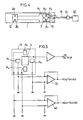
- Figs. 2A and 2B show the first embodiment of the present invention in which a flexible printed circuit (hereinafter referred to as FPC) board 1 is etched on its one side with a required electrode pattern (conductor circuit 19).
- FPC flexible printed circuit
- a light emitter 2 and a light receptor 3 are mounted on the FPC board 1 in position and connected to the conductor circuit 19 by soldering.
- a cable 15 is also connected at one end of the FPC board to the conductor circuit 19 by soldering.
- the light emitter 2 is a several-millimeter square chip having two light emitting diodes mounted thereon.
- the lights emitted from the two diodes have different wavelengths from each other.
- the transmittance of one of the lights through the body of an examinee is used as a reference on the basis of which the transmittance of the other is measured.
- Two diodes are used for precise measurement.
- the cable 15 is a five-core cable, three of the five cores for activating the emitter 2 and the other two for relaying the signals from the receptor 3.
- the photosensor in the first embodiment should preferably be provided with protective layers 16 and 17 as shown in Fig. 3.
- the layer 16 covering the light emitter 2 and the light receptor 3 is made of a transparent resin or glass.
- the layer 17 covering the other part of the photosensor is made of an insulating and flexible resin such as epoxy, urethane or silicone resin.
- the photosensor in this embodiment is applied e.g. to a finger so as to sandwich the finger with the emitter 2 and the receptor 3 opposed to each other at both sides of the finger and fixed in position by means of a fixing tape.
- the light emitter 2 is then activated to emit two beams of light having different wavelengths from each other.
- the beams are transmitted through the finger to hit upon the receptor 3.
- the light beams recei′,ed on the receptor are analyzed to determine the content of pigment in the blood stream, etc.
- the FPC board is used as supports for the light emitter and the light receptor and they are connected to the cable through the conductor circuit on the FPC board. It is not necessary to mount the cable on FPC so as to extend in its longitudinal direction. It is thus not necessary to apply a tape for fixing the cable to the FPC board, either.
- the photosensor in this embodiment is more flexible and can be fitted more comfortably on a finger or the like. Further, its reliability is increased and the production cost is reduced.
- Fig. 4 shows the second embodiment of the present invention in which four position sensors A1 to A4 are provided around the light receptor 3 to judge whether or not the receptor is in an exactly opposite position to the light emitter 2.
- the sensors A1 and A2 are arranged in front and rear of the receptor 3 to determine whether they are in exactly opposite position in the longitudinal direction of finger and the sensor A3 and A4 are arranged at both sides of the receptor 3 to determine whether they are in an exactly opposite position in the transverse direction of the finger.
- the light emitting diodes 2a and 2b, the receptor 3 and the four position sensors A1 to A4 are connected to a main body 20 through lead wires 15 and a connector 10.
- Fig. 5 is a circuit diagram showing how the photosensor of the second embodiment operates.
- An electric current IA1 which flows through the sensor A1 and a current IA1which flows through the sensor A2 are compared with each other in an IC comparator 30 to check the position of the receptor 3 in a widthwise direction of the finger. The result is expressed as IS1 .
- Currents IA3 and IA4 which flow through the sensors A3 and A4, respectively, are compared in an IC comparator 40 to check the position of the receptor 3 in a longitudinal direction of the finger. The result is expressed as IS2.
- the receptor 3 gives an output IB representative of the light tranmittance.
- the position sensors and comparator means such as IC comparators constitute a position displacement detecting means.
- the relationship between the currents Is1 and IS2 will be expressed by the inequality
- an alarm may be set off to give a warning to an operator so that he can refit the photosensor to correct the relative position between the emitter and the receptor.
- two pairs of position sensors are used, they may be provided in any number of pairs. For example, even one pair would be of a great help in checking the relative position between the emitter and the receptor.
- the number of light emitting diodes provided in the emitter is not limited to two but may be one or three or more.
- any positional displacement between the emitter and the receptor is detected by comparing the electric signals from the position sensors. If any displacement is detected, an operator is notified immediately so that he can refit the photosensor so as to arrange the emitter and receptor in exactly opposite positions. Since the emitter and receptor can be positioned exactly in a face-to-face relationship, it is not necessary to increase the power of the emitter to such an extent as to give a burn on the finger. Nor is it necessary to amplify the sensitivity of the receptor which would lower the S/N ratio and thus the precision of the sensor. This will increase the reliability of the bio-photosensor.
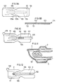
- the third embodiment is shown in Figs. 6A, 6B and 7. This embodiment is substantially the same as the first embodiment except for the following points.
- the photosensor is provided with a mark 8 at a position where the tip of the nail of a finger contacts when the photosensor is put on the finger.
- the mark 8 may be in the form of a projection or a mere flat sign.
- the bio-photosensor in this embodiment is put on a finger with reference to Fig. 7.
- the photosensor 6 is applied to a finger 7 so as to extend in its longitudinal direction with the mark 8 in contact with the tip of the fingernail 7a.
- the photosensor is turned back at the tip of the fingernail.
- the mark 8 should be provided on the FPC board at such a position that the emitter 2 and the receptor 3 will be put in exactly opposite position to each other when the photosensor 6 is fitted on the finger in the above-described manner.
- Figs. 8A to 8C show the fourth embodiment of the present invention which is a modification of the third embodiment.
- the mark 8 in the third embodiment serves as a mere standard for the relative position between the emitter and the receptor because the shape and length of the nail and finger differ from person to person.
- second marks 9a and 9b are provided on the fixing tape 5 on its back side so as to be located right behind the emitter 2 and the receptor 3, respectively. They may be projections or mere flat marks.
- the photosensor of the fourth embodiment is applied to a finger with reference to Fig. 8C.
- the photosensor 6 is turned back so as to wrap the finger 7 in its longitudinal direction.
- the emitter 2 and the receptor 3 can be put in exactly opposite positions to each other by aligning the mark 9a located right behind the emitter 2 with the mark 9b located right behind the receptor 3.
- the photosensor is fixed in position.
- the second marks 9a and 9b will thus allow the emitter and the receptor to be put in right positions irrespective of the length of the nail and the shape of the finger.
- Figs. 9A and 9B show the fixing tape used in the fifth embodiment of the present invention.
- the fixing tape 5 comprises a substrate 101, an adhesive layer 102 bonded to one side of the substrate 101, a release paper 103 laminated on the adhesive layer 102.
- the release paper 103 has a tab portion 104 and is formed with cutouts 105 at both sides so as to be opposed to each other.
- the cutouts 105 are used as a positioning mark when applying the photosensor to a finger of an examinee. Namely, the emitter and the receptor are mounted on the finger so as to oppose to each other when the photosensor is put on the finger with its cutouts 105 at the tip of the finger, as shown in Fig. 11. But, it is required that the emitter and the receptor are exactly positioned with respect to the substrate 101.
- the substrate 101 is provided on its surface behind the emitter and the receptor with a printed mark 106 so as to indicate the positions of the emitter and the receptor.
- the cutouts 105 serve also to form voids 105a and 105b as shown in Fig. 9A. If no voids 105a and 105b are formed, these portions may stick together when the substrate 101 is put on the finger, thus pressing the finger so tightly as to cause it to be congested with blood.
- Fig. 10 shows the sixth embodiment in which the release paper 103 in the fifth embodiment is modified. Namely, it is formed with a perforated weak line 107 which outlines a portion on which the emitter and the receptor are to be mounted.
- the perforated line 107 may be replaced with a half-cut line or a continuous through-cut line.
- a tab 108 is provided at one end of the portion enclosed in the perforated line 107.
- Another tab 109 is provided at a desired portion along the edge of the release paper 103 and outside the portion enclosed in the line 107.
- the release paper 103 there are printed letters 110 which indicate the positions of the emitter and the receptor and a mark 111 which indicates the mounting position of a part (a finger in the drawing) of the body of the examinee.
- the same mark 111 should be printed on one side of the substrate 101, too, at a position corresponding to the mark on the release paper 103.
- the release paper 103 is peeled firstly only at the portion enclosed in the weak line 107 to expose a part of the adhesive layer 102 as shown in Fig. 12. Then the emitter and the receptor are stuck in position on the exposed part of the adhesive layer 103. Next, the remainder of the release paper is peeled off. Thus, the emitter and the receptor can be mounted in exact positions easily. Since the adhesive layer 102 is covered with the release paper 103 except the portion enclosed in the weak line 107, until right before the tape is applied to the finger, its bonding strength is kept high.
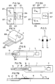
- FIGs. 13A, 13B, and 14 show an example of the light emitter used in the present invention.
- a multi-wavelength light emitter 210 (Fig. 14) includes a glass-epoxy board 201 having its entire surface except the electrodes subjected to etching.
- Light emitting diodes 202 and 203 having different wavelengths are connected to a common cathode 204 and to anodes 205 and 206, respectively.
- the light emitting diodes 202 and 203 are mounted on the circuit board 201 by wire bonding or die bonding.
- electrodes 204′, 205′ and 206′ are provided which correspond to the electrodes 204, 205, and 206, respectively.
- Each pair of the electrodes 204 and 204′, 205 and 205′ and 206 and 206′ are electrically connected together through a hole 207.
- the electrodes 204′, 205′ and 206′ on the other side of the circuit board 201 are connected to lead wires or directly connected to another circuit board.
- the light emitting diodes 202 and 203 mounted on the epoxy-glass board 201 are covered with a clear epoxy resin 208.
- Three lead wires 209 come from the back of the board 201.
- the board 201 may be a 3 mm by 3 mm square with a height of 2 mm, for example.
- the light emitting diodes 202 and 203 emit beams A1 having a wavelength of 805 nm and beams A2 having 1 a wavelength of 940 nm, respectively. (Fig. 15).
- Fig. 16 shows the seventh embodiment in which the multi-wavelength light emitter 210 and the light receptor 3 are mounted on the FPC board 1 formed with a printed wiring pattern 212.
- the lead wires 209 and the wiring pattern 212 are connected to the cable 15.
- the FPC board 1 is coated with an insulating urethane resin.
- the FPC board 1 is put on the finger tip 7 in the manner as shown in Fig. 11 so that the light emitter 210 and the receptor 3 will oppose to each other at both sides of the finger tip 7.
- the photosensor can be fitted easily on the finger tip or the like to measure e.g. the concentration of a specific pigment injected into the body of the examinee. Further, since the two light emitting diodes are arranged very close to each other, the beams emitted therefrom and having different wavelengths from each other can be regarded as originated from a single light source. This will simplify the signal processing.
- Figs. 17A and 17B show the eighth embodiment which is a modification of the seventh embodiment.
- the FPC board 1 is integrally formed at its one end with a narrow strip 26.
- One end of the cable is put on the strip 26 and bonded thereto.
- a heat-shrinkable tube 27 is put on the overlapped portion and heated so as to be shrunk on the overlapped portion.
- the photosensor as well as part of the heat-shrinkable tube 27 may be coated with a flexible resin to protect the entire photosensor especially its connections to wires.
- a coating has to be transparent at portions covering the beam emitting and receiving faces of the emitter and the receptor. If this coating is applied to a stick-on type sensor other than a photosensor, it may or may not be transparent.
- the cable has its one end overlapped with the bonded to the narrow strip of projection of the circuit board. Further, the heat-shrinkable tube is put on the overlapped portion and tightened to reinforce the bonding connection therebetween. The cable is thus less likely to get disconnected or broken. This will allow the base for the sensor elements to be made of FPC.
- the photosensor having an FPC base is superior in flexibility, easy to manufacture and can be fitted easily and comfortably. Still, its reliability is sufficiently high.
Landscapes
- Health & Medical Sciences (AREA)
- Life Sciences & Earth Sciences (AREA)
- Physics & Mathematics (AREA)
- Surgery (AREA)
- General Health & Medical Sciences (AREA)
- Engineering & Computer Science (AREA)
- Biomedical Technology (AREA)
- Heart & Thoracic Surgery (AREA)
- Medical Informatics (AREA)
- Molecular Biology (AREA)
- Biophysics (AREA)
- Animal Behavior & Ethology (AREA)
- Pathology (AREA)
- Public Health (AREA)
- Veterinary Medicine (AREA)
- Cardiology (AREA)
- Spectroscopy & Molecular Physics (AREA)
- Optics & Photonics (AREA)
- Physiology (AREA)
- Measurement Of The Respiration, Hearing Ability, Form, And Blood Characteristics Of Living Organisms (AREA)
- Measuring Pulse, Heart Rate, Blood Pressure Or Blood Flow (AREA)
Abstract
Description
- The present invention relates to a bio-photosensor adapted to be fixed to a part of the body of an examinee e.g. a finger to measure the absorption of the light emitted from one side of the finger and transmitted through the finger to the other side.
- This type of sensor is used e.g. to examine the function of the liver of an examinee. In this examination, a specific pigment which is selectively taken into and excreted from only the liver is injected into the blood stream. Then the concentration of the pigment in blood plasma is measured with the sensor to determine the blood plasma disappearance rate and retention ratio of the pigment to examine the function of the liver.
- As one example of such prior art photosensors, there is known a bio-photosensor which is applied to a finger and in which light is transmitted from one side of the finger to the other side so as to detect the fluctuation of transmittance or reflectance of light due to the blood flow. Signals representative of such fluctuations are processed and calculated to obtain such vital information as pulse rates or blood pressures (see Japanese Unexamined Patent Publication No. 60-34432 and Japanese Unexamined Utility Model Publication No. 60-158803).
- Figs. 1A and 1B show a prior art bio-photosensor comprising a strip of
flexible base film 1, and alight emitter 2 and alight receptor 3 mounted on thebase film 1 and spaced longitudinally from each other. Theemitter 2 and thereceptor 3 are connected respectively to leadwires 4. Anadhesive tape 5 is used to fix thephotosensor 6 to a finger. - The
base film 1 provided with theemitter 2 and thereceptor 3 is applied to afinger 7 in its longitudinal direction and turned back at thefinger tip 7a. (Fig. 1C) Thetape 5 is then put over thebase film 1 to fix thephotosensor 6 to thefinger 7. - In this state, the
sensor 6 is turned on to cause thelight emitter 2 to give forth light which passes through thefinger 7 and strikes thereceptor 3. In response thereto, thereceptor 3 applies signals to a signal processor (not shown) through thelead wire 4 and a connector (not shown). The processor will process the signals about the fluctuation of light transmittance to obtain vital information such as pulse rate and blood pressure. - In this prior art photosensor, wires are directly connected to the emitter and the receptor and they have to be fixed to the flexible base film. Means and step of fixing the wires to the base film will add to the cost of the photosensor.
- Also, the rigidity of lead wires extending in the longitudinal direction of the base film will lower the flexibility of the base film. Such a photosensor could not be comfortably fitted on part of the body of an examinee. Further, there was a fear that the wire or cable might be pulled out of the sensor or be broken at their connections during use only with a small tensile or bending stress which tends to act on the connections.
- In Fig. 1C, the
emitter 2 and thereceptor 3 are set in exactly opposite positions to each other. But if they are not, it is necessary to increase the power of theemitter 2 or the amplifying factor of thereceptor 3. If the power of the emitter is increased, the finger might be burned owing to a heat buildup of the emitter. An increase in the amplifying factor of the receptor would impair the S/N ratio, thus lowering the accuracy of the photosensor. This problem results from the fact that the photosensor is not equipped with means for ensuring the relative position between theemitter 2 and thereceptor 3 when the photosensor is fitted on the finger. - Such a prior art photosensor is provided on its base film with a light emitter capable of emitting two beams having different wavelengths from each other. But no photosensor is equipped with a light emitter capable of emitting two beams, one of the beams having such a wavelength as to be absorbed almost entirely by a specific pigment which is removed exclusively by the hepatic parenchyma once it is injected into the blood and the other having such a wavelength as not to be absorbed by the abovesaid pigment. Elaborate equipment was therefore necessary to measure the absorption of a pigment e.g. in the blood.
- It is an object of the present invention to provide a bio-photosensor which can be fitted on a part of the body of an examinee easily and comfortably.
- In accordance with the present invention, there is provided a bio-photosensor comprising a flexible printed circuit board formed with an electric circuit and adapted to be wrapped around a part of the body of an examinee, and a light emitter and a light receptor mounted on the printed circuit board with some distance therebetween so that they will be opposed to each other at both sides of the part of the examinee when the printed circuit board is wrapped therearound, the light emitter and the light receptor being electrically connected through the electric circuit to an electric cable connected to one end of the printed circuit board.
- It is another object of the present invention to provide a bio-photosensor which allows the light emitter and the light receptor to be disposed in exactly opposite positions to each other when the bio-photosensor is fitted on a finger or the like.
- In accordance with the present invention, there is provided a position displacement detector means which has a pair of sensors in the vicinity of the light receptor to check whether or not the light receptor is exactly opposed to the light emitter.
- As another means for this purpose, there is provided a bio-photosensor having a strip of flexible printed circuit board provided with a mark at a portion adapted to be brought into contact with the tip of a fingernail.
- In accordance with the present invention, a bio-photosensor is provided which is capable of emitting a plurality of beans having different wavelengths from one another, one of said beams having such a wavelength as to be absorbed by a specific pigment which is removed exclusively by the hepatic parenchyma when it is injected into the blood, and the others having such wavelengths as not to be absorbed in this pigment. In order to accomplish this object, one light emitter comprises a light emitting diode emitting a beam of the first wavelength and another light emitting diode emitting a beam of the second wavelength.
- Other features and objects of the present invention will become apparent from the following description taken with reference to the accompanying drawings, in which:
- Fig. 1A is a plan view of a prior art bio-photosensor;
- Fig. 1B is a front view of the same;
- Fig. 1C is a sectional side view of the same fitted on a finger;
- Fig. 2A is a plan view of the first embodiment of the photosensor according to the present invention;
- Fig. 2B is a front view of the same;
- Fig. 3 is a front view of a modification of the first embodiment;
- Fig. 4 is a plan view of the second embodiment;
- Fig. 5 is a circuit diagram showing how the photosensor of the second embodiment works;
- Fig. 6A is a plan view of the third embodiment;
- Fig. 6B is a front view of the same;
- Fig. 7 is a side view of the same showing how it is fitted on a finger;
- Fig. 8A is a plan view of the fourth embodiment;
- Fig. 8B is a front view of the same;
- Fig. 8C is a side view of the same showing how it is fitted on a finger;
- Fig. 9A is a plan view of the fixing tape of the photosensor of the fifth embodiment of the present invention;
- Fig. 9B is a front view of the same;
- Fig. 10 is a plan view of the release paper of the photosensor of the sixth embodiment;
- Fig. 11 is a sectional view of the fifth embodiment showing how it is fitted on a finger;
- Fig. 12 is a plan view of the fixing tape of the sixth embodiment with the release paper partially peeled off;
- Fig. 13A is a plan view of the multi-wavelength light emitter used in the bio-photosensor of the seventh embodiment with the cover removed;
- Fig. 13B is a bottom view of the same;
- Fig. 14 is a perspective view of the multi-wavelength light emitter;
- Fig. 15 is a block diagram of the same;
- Fig. 16 is a plan view of the seventh embodiment equipped with the multi-wavelength light emitter of Fig.14;
- Fig. 17A is a plan view of the eighth embodiment; and
- Fig. 17B is a front view of the same.
- Figs. 2A and 2B show the first embodiment of the present invention in which a flexible printed circuit (hereinafter referred to as FPC)
board 1 is etched on its one side with a required electrode pattern (conductor circuit 19). Alight emitter 2 and alight receptor 3 are mounted on theFPC board 1 in position and connected to theconductor circuit 19 by soldering. Acable 15 is also connected at one end of the FPC board to theconductor circuit 19 by soldering. - The
light emitter 2 is a several-millimeter square chip having two light emitting diodes mounted thereon. The lights emitted from the two diodes have different wavelengths from each other. The transmittance of one of the lights through the body of an examinee is used as a reference on the basis of which the transmittance of the other is measured. Two diodes are used for precise measurement. - As the
light receptor 3, a silicon photodiode is used. Thecable 15 is a five-core cable, three of the five cores for activating theemitter 2 and the other two for relaying the signals from thereceptor 3. - The photosensor in the first embodiment should preferably be provided with
protective layers layer 16 covering thelight emitter 2 and thelight receptor 3 is made of a transparent resin or glass. Thelayer 17 covering the other part of the photosensor is made of an insulating and flexible resin such as epoxy, urethane or silicone resin. - The photosensor in this embodiment is applied e.g. to a finger so as to sandwich the finger with the
emitter 2 and thereceptor 3 opposed to each other at both sides of the finger and fixed in position by means of a fixing tape. Thelight emitter 2 is then activated to emit two beams of light having different wavelengths from each other. The beams are transmitted through the finger to hit upon thereceptor 3. The light beams recei′,ed on the receptor are analyzed to determine the content of pigment in the blood stream, etc. - In this embodiment, the FPC board is used as supports for the light emitter and the light receptor and they are connected to the cable through the conductor circuit on the FPC board. It is not necessary to mount the cable on FPC so as to extend in its longitudinal direction. It is thus not necessary to apply a tape for fixing the cable to the FPC board, either. The photosensor in this embodiment is more flexible and can be fitted more comfortably on a finger or the like. Further, its reliability is increased and the production cost is reduced.
- Fig. 4 shows the second embodiment of the present invention in which four position sensors A₁ to A₄ are provided around the
light receptor 3 to judge whether or not the receptor is in an exactly opposite position to thelight emitter 2. The sensors A₁ and A₂ are arranged in front and rear of thereceptor 3 to determine whether they are in exactly opposite position in the longitudinal direction of finger and the sensor A₃ and A₄ are arranged at both sides of thereceptor 3 to determine whether they are in an exactly opposite position in the transverse direction of the finger. Thelight emitting diodes receptor 3 and the four position sensors A₁ to A₄ are connected to amain body 20 throughlead wires 15 and aconnector 10. - Fig. 5 is a circuit diagram showing how the photosensor of the second embodiment operates. An electric current IA₁ which flows through the sensor A₁ and a current IA₁which flows through the sensor A₂ are compared with each other in an
IC comparator 30 to check the position of thereceptor 3 in a widthwise direction of the finger. The result is expressed as IS₁ . Currents IA₃ and IA₄ which flow through the sensors A₃ and A₄, respectively, are compared in anIC comparator 40 to check the position of thereceptor 3 in a longitudinal direction of the finger. The result is expressed as IS₂. Thereceptor 3 gives an output IB representative of the light tranmittance. The position sensors and comparator means such as IC comparators constitute a position displacement detecting means. - If the emitter and the receptor are out of mutually opposite positions, the relationship between the currents Is₁ and IS₂ will be expressed by the inequality |IS₁| ≧IS₀ |IS₂|≧IS₀, wherein IS₀ represents a preset current. In such a case, an alarm may be set off to give a warning to an operator so that he can refit the photosensor to correct the relative position between the emitter and the receptor.
- Though in this embodiment, two pairs of position sensors are used, they may be provided in any number of pairs. For example, even one pair would be of a great help in checking the relative position between the emitter and the receptor.
- Also, the number of light emitting diodes provided in the emitter is not limited to two but may be one or three or more.
- Any positional displacement between the emitter and the receptor is detected by comparing the electric signals from the position sensors. If any displacement is detected, an operator is notified immediately so that he can refit the photosensor so as to arrange the emitter and receptor in exactly opposite positions. Since the emitter and receptor can be positioned exactly in a face-to-face relationship, it is not necessary to increase the power of the emitter to such an extent as to give a burn on the finger. Nor is it necessary to amplify the sensitivity of the receptor which would lower the S/N ratio and thus the precision of the sensor. This will increase the reliability of the bio-photosensor.
- The third embodiment is shown in Figs. 6A, 6B and 7. This embodiment is substantially the same as the first embodiment except for the following points.
- As shown in Figs. 6A and 6B, the photosensor is provided with a
mark 8 at a position where the tip of the nail of a finger contacts when the photosensor is put on the finger. Themark 8 may be in the form of a projection or a mere flat sign. - Next, it will be described how the bio-photosensor in this embodiment is put on a finger with reference to Fig. 7. The
photosensor 6 is applied to afinger 7 so as to extend in its longitudinal direction with themark 8 in contact with the tip of thefingernail 7a. The photosensor is turned back at the tip of the fingernail. Themark 8 should be provided on the FPC board at such a position that theemitter 2 and thereceptor 3 will be put in exactly opposite position to each other when thephotosensor 6 is fitted on the finger in the above-described manner. - Figs. 8A to 8C show the fourth embodiment of the present invention which is a modification of the third embodiment. The
mark 8 in the third embodiment serves as a mere standard for the relative position between the emitter and the receptor because the shape and length of the nail and finger differ from person to person. In this embodiment, besides themark 8,second marks tape 5 on its back side so as to be located right behind theemitter 2 and thereceptor 3, respectively. They may be projections or mere flat marks. - Next, it will be described how the photosensor of the fourth embodiment is applied to a finger with reference to Fig. 8C. After bringing the
mark 8 into contact with the tip of thefingernail 7a as in the third embodiment, thephotosensor 6 is turned back so as to wrap thefinger 7 in its longitudinal direction. Theemitter 2 and thereceptor 3 can be put in exactly opposite positions to each other by aligning themark 9a located right behind theemitter 2 with themark 9b located right behind thereceptor 3. Then the photosensor is fixed in position. Thesecond marks - Figs. 9A and 9B show the fixing tape used in the fifth embodiment of the present invention. The fixing
tape 5 comprises asubstrate 101, anadhesive layer 102 bonded to one side of thesubstrate 101, arelease paper 103 laminated on theadhesive layer 102. Therelease paper 103 has atab portion 104 and is formed withcutouts 105 at both sides so as to be opposed to each other. Thecutouts 105 are used as a positioning mark when applying the photosensor to a finger of an examinee. Namely, the emitter and the receptor are mounted on the finger so as to oppose to each other when the photosensor is put on the finger with itscutouts 105 at the tip of the finger, as shown in Fig. 11. But, it is required that the emitter and the receptor are exactly positioned with respect to thesubstrate 101. For this purpose, thesubstrate 101 is provided on its surface behind the emitter and the receptor with a printedmark 106 so as to indicate the positions of the emitter and the receptor. - The
cutouts 105 serve also to formvoids voids substrate 101 is put on the finger, thus pressing the finger so tightly as to cause it to be congested with blood. - Fig. 10 shows the sixth embodiment in which the
release paper 103 in the fifth embodiment is modified. Namely, it is formed with a perforatedweak line 107 which outlines a portion on which the emitter and the receptor are to be mounted. Theperforated line 107 may be replaced with a half-cut line or a continuous through-cut line. Atab 108 is provided at one end of the portion enclosed in theperforated line 107. Anothertab 109 is provided at a desired portion along the edge of therelease paper 103 and outside the portion enclosed in theline 107. Further, on therelease paper 103, there are printedletters 110 which indicate the positions of the emitter and the receptor and amark 111 which indicates the mounting position of a part (a finger in the drawing) of the body of the examinee. Thesame mark 111 should be printed on one side of thesubstrate 101, too, at a position corresponding to the mark on therelease paper 103. - In use, the
release paper 103 is peeled firstly only at the portion enclosed in theweak line 107 to expose a part of theadhesive layer 102 as shown in Fig. 12. Then the emitter and the receptor are stuck in position on the exposed part of theadhesive layer 103. Next, the remainder of the release paper is peeled off. Thus, the emitter and the receptor can be mounted in exact positions easily. Since theadhesive layer 102 is covered with therelease paper 103 except the portion enclosed in theweak line 107, until right before the tape is applied to the finger, its bonding strength is kept high. - Figs. 13A, 13B, and 14 show an example of the light emitter used in the present invention. A multi-wavelength light emitter 210 (Fig. 14) includes a glass-
epoxy board 201 having its entire surface except the electrodes subjected to etching.Light emitting diodes common cathode 204 and toanodes light emitting diodes circuit board 201 by wire bonding or die bonding. - On the other side of the
circuit board 201,electrodes 204′, 205′ and 206′ are provided which correspond to theelectrodes electrodes hole 207. Theelectrodes 204′, 205′ and 206′ on the other side of thecircuit board 201 are connected to lead wires or directly connected to another circuit board. - As shown in Fig. 14, the
light emitting diodes glass board 201 are covered with aclear epoxy resin 208. Threelead wires 209 come from the back of theboard 201. Theboard 201 may be a 3 mm by 3 mm square with a height of 2 mm, for example. - The
light emitting diodes - Fig. 16 shows the seventh embodiment in which the
multi-wavelength light emitter 210 and thelight receptor 3 are mounted on theFPC board 1 formed with a printedwiring pattern 212. Thelead wires 209 and thewiring pattern 212 are connected to thecable 15. In this embodiment, theFPC board 1 is coated with an insulating urethane resin. - In use, the
FPC board 1 is put on thefinger tip 7 in the manner as shown in Fig. 11 so that thelight emitter 210 and thereceptor 3 will oppose to each other at both sides of thefinger tip 7. - Since the light emitter of the photosensor in this embodiment is of a compact one-chip type, the photosensor can be fitted easily on the finger tip or the like to measure e.g. the concentration of a specific pigment injected into the body of the examinee. Further, since the two light emitting diodes are arranged very close to each other, the beams emitted therefrom and having different wavelengths from each other can be regarded as originated from a single light source. This will simplify the signal processing.
- Figs. 17A and 17B show the eighth embodiment which is a modification of the seventh embodiment. As shown in Fig. 17A, the
FPC board 1 is integrally formed at its one end with anarrow strip 26. One end of the cable is put on thestrip 26 and bonded thereto. A heat-shrinkable tube 27 is put on the overlapped portion and heated so as to be shrunk on the overlapped portion. - The photosensor as well as part of the heat-
shrinkable tube 27 may be coated with a flexible resin to protect the entire photosensor especially its connections to wires. Such a coating has to be transparent at portions covering the beam emitting and receiving faces of the emitter and the receptor. If this coating is applied to a stick-on type sensor other than a photosensor, it may or may not be transparent. - In this embodiment, the cable has its one end overlapped with the bonded to the narrow strip of projection of the circuit board. Further, the heat-shrinkable tube is put on the overlapped portion and tightened to reinforce the bonding connection therebetween. The cable is thus less likely to get disconnected or broken. This will allow the base for the sensor elements to be made of FPC. The photosensor having an FPC base is superior in flexibility, easy to manufacture and can be fitted easily and comfortably. Still, its reliability is sufficiently high.
Claims (10)
Applications Claiming Priority (14)
| Application Number | Priority Date | Filing Date | Title |
|---|---|---|---|
| JP168041/87 | 1987-11-02 | ||
| JP168040/87 | 1987-11-02 | ||
| JP1987168043U JPH0174251U (en) | 1987-11-02 | 1987-11-02 | |
| JP1987168040U JPH0172204U (en) | 1987-11-02 | 1987-11-02 | |
| JP16803987U JPH0510808Y2 (en) | 1987-11-02 | 1987-11-02 | |
| JP1987168042U JPH0616908Y2 (en) | 1987-11-02 | 1987-11-02 | Sensor mounting tape |
| JP168042/87 | 1987-11-02 | ||
| JP1987168041U JPH0171454U (en) | 1987-11-02 | 1987-11-02 | |
| JP168039/87 | 1987-11-02 | ||
| JP168043/87 | 1987-11-02 | ||
| JP17419087U JPH0532083Y2 (en) | 1987-11-13 | 1987-11-13 | |
| JP174190/87 | 1987-11-13 | ||
| JP174189/87 | 1987-11-13 | ||
| JP17418987U JPH0510806Y2 (en) | 1987-11-13 | 1987-11-13 |
Publications (2)
| Publication Number | Publication Date |
|---|---|
| EP0315040A1 true EP0315040A1 (en) | 1989-05-10 |
| EP0315040B1 EP0315040B1 (en) | 1993-01-27 |
Family
ID=27566272
Family Applications (1)
| Application Number | Title | Priority Date | Filing Date |
|---|---|---|---|
| EP88117854A Expired - Lifetime EP0315040B1 (en) | 1987-11-02 | 1988-10-26 | Bio-photosensor |
Country Status (6)
| Country | Link |
|---|---|
| US (1) | US4974591A (en) |
| EP (1) | EP0315040B1 (en) |
| KR (1) | KR920000733B1 (en) |
| CA (1) | CA1323074C (en) |
| DE (1) | DE3877894T2 (en) |
| RU (1) | RU2096992C1 (en) |
Cited By (7)
| Publication number | Priority date | Publication date | Assignee | Title |
|---|---|---|---|---|
| DE3809084A1 (en) * | 1988-03-18 | 1989-09-28 | Nicolay Gmbh | Sensor for measuring the pulse rate and/or the oxygen saturation of the blood, and method for producing it |
| EP0587009A1 (en) * | 1992-08-28 | 1994-03-16 | Spacelabs Medical, Inc. | Alignment guide system for transmissive pulse oximetry sensors |
| WO1998008062A1 (en) * | 1996-08-16 | 1998-02-26 | The University Court Of The University Of Dundee | Manually operated signalling apparatus |
| WO2000078209A2 (en) * | 1999-06-18 | 2000-12-28 | Masimo Corporation | Pulse oximeter probe-off detection system |
| US6654624B2 (en) | 1999-03-25 | 2003-11-25 | Masimo Corporation | Pulse oximeter probe-off detector |
| GB2520487A (en) * | 2013-11-19 | 2015-05-27 | Eduardo Mangieri | Blood-flow sensor apparatus |
| WO2015173464A1 (en) * | 2014-05-15 | 2015-11-19 | Nokia Technologies Oy | An apparatus, method and computer program for a wearable device |
Families Citing this family (174)
| Publication number | Priority date | Publication date | Assignee | Title |
|---|---|---|---|---|
| DE3912993C2 (en) * | 1989-04-20 | 1998-01-29 | Nicolay Gmbh | Optoelectronic sensor for generating electrical signals based on physiological values |
| US5845639A (en) * | 1990-08-10 | 1998-12-08 | Board Of Regents Of The University Of Washington | Optical imaging methods |
| US5209230A (en) * | 1990-10-19 | 1993-05-11 | Nellcor Incorporated | Adhesive pulse oximeter sensor with reusable portion |
| US5237994A (en) * | 1991-03-12 | 1993-08-24 | Square One Technology | Integrated lead frame pulse oximetry sensor |
| US6541756B2 (en) | 1991-03-21 | 2003-04-01 | Masimo Corporation | Shielded optical probe having an electrical connector |
| US5638818A (en) | 1991-03-21 | 1997-06-17 | Masimo Corporation | Low noise optical probe |
| US5429129A (en) * | 1991-08-22 | 1995-07-04 | Sensor Devices, Inc. | Apparatus for determining spectral absorption by a specific substance in a fluid |
| US5368025A (en) * | 1991-08-22 | 1994-11-29 | Sensor Devices, Inc. | Non-invasive oximeter probe |
| US5246003A (en) * | 1991-08-28 | 1993-09-21 | Nellcor Incorporated | Disposable pulse oximeter sensor |
| US5263244A (en) * | 1992-04-17 | 1993-11-23 | Gould Inc. | Method of making a flexible printed circuit sensor assembly for detecting optical pulses |
| JP2547840Y2 (en) * | 1992-09-25 | 1997-09-17 | 日本光電工業株式会社 | Oximeter probe |
| EP0641543A1 (en) * | 1993-09-07 | 1995-03-08 | Ohmeda Inc. | Heat-sealed neo-natal medical monitoring probe |
| US5816245A (en) * | 1995-06-01 | 1998-10-06 | Manseur; Rachid | Electronic pneumothorax monitoring device |
| US5810724A (en) * | 1995-12-01 | 1998-09-22 | Nellcor Puritan Bennett Incorporated | Reusable sensor accessory containing a conformable spring activated rubber sleeved clip |
| US6018673A (en) | 1996-10-10 | 2000-01-25 | Nellcor Puritan Bennett Incorporated | Motion compatible sensor for non-invasive optical blood analysis |
| US20060161071A1 (en) | 1997-01-27 | 2006-07-20 | Lynn Lawrence A | Time series objectification system and method |
| US8932227B2 (en) | 2000-07-28 | 2015-01-13 | Lawrence A. Lynn | System and method for CO2 and oximetry integration |
| US9042952B2 (en) | 1997-01-27 | 2015-05-26 | Lawrence A. Lynn | System and method for automatic detection of a plurality of SPO2 time series pattern types |
| US9521971B2 (en) | 1997-07-14 | 2016-12-20 | Lawrence A. Lynn | System and method for automatic detection of a plurality of SPO2 time series pattern types |
| US20070191697A1 (en) | 2006-02-10 | 2007-08-16 | Lynn Lawrence A | System and method for SPO2 instability detection and quantification |
| US6721585B1 (en) | 1998-10-15 | 2004-04-13 | Sensidyne, Inc. | Universal modular pulse oximeter probe for use with reusable and disposable patient attachment devices |
| US7245953B1 (en) | 1999-04-12 | 2007-07-17 | Masimo Corporation | Reusable pulse oximeter probe and disposable bandage apparatii |
| USRE41912E1 (en) | 1998-10-15 | 2010-11-02 | Masimo Corporation | Reusable pulse oximeter probe and disposable bandage apparatus |
| US6675031B1 (en) * | 1999-04-14 | 2004-01-06 | Mallinckrodt Inc. | Method and circuit for indicating quality and accuracy of physiological measurements |
| US6950687B2 (en) | 1999-12-09 | 2005-09-27 | Masimo Corporation | Isolation and communication element for a resposable pulse oximetry sensor |
| KR100342578B1 (en) * | 1999-12-11 | 2002-06-28 | 이승헌 | Vending Machine of Photograph Representing Human Physiological Signal by Color and Form |
| US6801797B2 (en) | 2000-04-17 | 2004-10-05 | Nellcor Puritan Bennett Incorporated | Pulse oximeter sensor with piece-wise function |
| US8224412B2 (en) | 2000-04-17 | 2012-07-17 | Nellcor Puritan Bennett Llc | Pulse oximeter sensor with piece-wise function |
| US20060195041A1 (en) | 2002-05-17 | 2006-08-31 | Lynn Lawrence A | Centralized hospital monitoring system for automatically detecting upper airway instability and for preventing and aborting adverse drug reactions |
| US9053222B2 (en) | 2002-05-17 | 2015-06-09 | Lawrence A. Lynn | Patient safety processor |
| US6754516B2 (en) | 2001-07-19 | 2004-06-22 | Nellcor Puritan Bennett Incorporated | Nuisance alarm reductions in a physiological monitor |
| US6748254B2 (en) | 2001-10-12 | 2004-06-08 | Nellcor Puritan Bennett Incorporated | Stacked adhesive optical sensor |
| US7096054B2 (en) * | 2002-08-01 | 2006-08-22 | Masimo Corporation | Low noise optical housing |
| US7190986B1 (en) | 2002-10-18 | 2007-03-13 | Nellcor Puritan Bennett Inc. | Non-adhesive oximeter sensor for sensitive skin |
| US7006856B2 (en) * | 2003-01-10 | 2006-02-28 | Nellcor Puritan Bennett Incorporated | Signal quality metrics design for qualifying data for a physiological monitor |
| US7016715B2 (en) | 2003-01-13 | 2006-03-21 | Nellcorpuritan Bennett Incorporated | Selection of preset filter parameters based on signal quality |
| US7500950B2 (en) | 2003-07-25 | 2009-03-10 | Masimo Corporation | Multipurpose sensor port |
| US7190985B2 (en) | 2004-02-25 | 2007-03-13 | Nellcor Puritan Bennett Inc. | Oximeter ambient light cancellation |
| US7120479B2 (en) | 2004-02-25 | 2006-10-10 | Nellcor Puritan Bennett Inc. | Switch-mode oximeter LED drive with a single inductor |
| US7162288B2 (en) | 2004-02-25 | 2007-01-09 | Nellcor Purtain Bennett Incorporated | Techniques for detecting heart pulses and reducing power consumption in sensors |
| US7194293B2 (en) | 2004-03-08 | 2007-03-20 | Nellcor Puritan Bennett Incorporated | Selection of ensemble averaging weights for a pulse oximeter based on signal quality metrics |
| US7534212B2 (en) | 2004-03-08 | 2009-05-19 | Nellcor Puritan Bennett Llc | Pulse oximeter with alternate heart-rate determination |
| US8611977B2 (en) * | 2004-03-08 | 2013-12-17 | Covidien Lp | Method and apparatus for optical detection of mixed venous and arterial blood pulsation in tissue |
| DE102005047170A1 (en) * | 2004-10-05 | 2006-07-20 | Sharp K.K. | Electronic device e.g. optical device used for optical connector, has no wiring pattern at outer periphery edge or its vicinity of mold resin and between surface of substrate and base |
| US7392075B2 (en) | 2005-03-03 | 2008-06-24 | Nellcor Puritan Bennett Incorporated | Method for enhancing pulse oximetry calculations in the presence of correlated artifacts |
| US7657294B2 (en) | 2005-08-08 | 2010-02-02 | Nellcor Puritan Bennett Llc | Compliant diaphragm medical sensor and technique for using the same |
| US7590439B2 (en) | 2005-08-08 | 2009-09-15 | Nellcor Puritan Bennett Llc | Bi-stable medical sensor and technique for using the same |
| US7657295B2 (en) | 2005-08-08 | 2010-02-02 | Nellcor Puritan Bennett Llc | Medical sensor and technique for using the same |
| US20070060808A1 (en) | 2005-09-12 | 2007-03-15 | Carine Hoarau | Medical sensor for reducing motion artifacts and technique for using the same |
| US7899510B2 (en) | 2005-09-29 | 2011-03-01 | Nellcor Puritan Bennett Llc | Medical sensor and technique for using the same |
| US7725147B2 (en) | 2005-09-29 | 2010-05-25 | Nellcor Puritan Bennett Llc | System and method for removing artifacts from waveforms |
| US7725146B2 (en) | 2005-09-29 | 2010-05-25 | Nellcor Puritan Bennett Llc | System and method for pre-processing waveforms |
| US8092379B2 (en) | 2005-09-29 | 2012-01-10 | Nellcor Puritan Bennett Llc | Method and system for determining when to reposition a physiological sensor |
| US7869850B2 (en) | 2005-09-29 | 2011-01-11 | Nellcor Puritan Bennett Llc | Medical sensor for reducing motion artifacts and technique for using the same |
| US7904130B2 (en) | 2005-09-29 | 2011-03-08 | Nellcor Puritan Bennett Llc | Medical sensor and technique for using the same |
| US7881762B2 (en) | 2005-09-30 | 2011-02-01 | Nellcor Puritan Bennett Llc | Clip-style medical sensor and technique for using the same |
| US8233954B2 (en) | 2005-09-30 | 2012-07-31 | Nellcor Puritan Bennett Llc | Mucosal sensor for the assessment of tissue and blood constituents and technique for using the same |
| US7483731B2 (en) | 2005-09-30 | 2009-01-27 | Nellcor Puritan Bennett Llc | Medical sensor and technique for using the same |
| US7486979B2 (en) | 2005-09-30 | 2009-02-03 | Nellcor Puritan Bennett Llc | Optically aligned pulse oximetry sensor and technique for using the same |
| US7555327B2 (en) | 2005-09-30 | 2009-06-30 | Nellcor Puritan Bennett Llc | Folding medical sensor and technique for using the same |
| US8062221B2 (en) | 2005-09-30 | 2011-11-22 | Nellcor Puritan Bennett Llc | Sensor for tissue gas detection and technique for using the same |
| US20070106126A1 (en) | 2005-09-30 | 2007-05-10 | Mannheimer Paul D | Patient monitoring alarm escalation system and method |
| JP2007105316A (en) * | 2005-10-14 | 2007-04-26 | Konica Minolta Sensing Inc | Bioinformation measuring instrument |
| US20070100220A1 (en) | 2005-10-28 | 2007-05-03 | Baker Clark R Jr | Adjusting parameters used in pulse oximetry analysis |
| US7990382B2 (en) | 2006-01-03 | 2011-08-02 | Masimo Corporation | Virtual display |
| US7668579B2 (en) | 2006-02-10 | 2010-02-23 | Lynn Lawrence A | System and method for the detection of physiologic response to stimulation |
| US8702606B2 (en) | 2006-03-21 | 2014-04-22 | Covidien Lp | Patient monitoring help video system and method |
| CA2650289A1 (en) * | 2006-04-25 | 2008-03-27 | University Of South Florida | Portable reactor for real-time nucleic acid amplification and detection |
| US7966768B2 (en) * | 2006-05-01 | 2011-06-28 | Laminations, Inc. | Staking system for growing container |
| US7477924B2 (en) | 2006-05-02 | 2009-01-13 | Nellcor Puritan Bennett Llc | Medical sensor and technique for using the same |
| US8073518B2 (en) | 2006-05-02 | 2011-12-06 | Nellcor Puritan Bennett Llc | Clip-style medical sensor and technique for using the same |
| US7522948B2 (en) | 2006-05-02 | 2009-04-21 | Nellcor Puritan Bennett Llc | Medical sensor and technique for using the same |
| US10188348B2 (en) | 2006-06-05 | 2019-01-29 | Masimo Corporation | Parameter upgrade system |
| US8380271B2 (en) | 2006-06-15 | 2013-02-19 | Covidien Lp | System and method for generating customizable audible beep tones and alarms |
| US8145288B2 (en) | 2006-08-22 | 2012-03-27 | Nellcor Puritan Bennett Llc | Medical sensor for reducing signal artifacts and technique for using the same |
| US8219170B2 (en) | 2006-09-20 | 2012-07-10 | Nellcor Puritan Bennett Llc | System and method for practicing spectrophotometry using light emitting nanostructure devices |
| US8195264B2 (en) | 2006-09-22 | 2012-06-05 | Nellcor Puritan Bennett Llc | Medical sensor for reducing signal artifacts and technique for using the same |
| US8175671B2 (en) | 2006-09-22 | 2012-05-08 | Nellcor Puritan Bennett Llc | Medical sensor for reducing signal artifacts and technique for using the same |
| US8396527B2 (en) | 2006-09-22 | 2013-03-12 | Covidien Lp | Medical sensor for reducing signal artifacts and technique for using the same |
| US7869849B2 (en) | 2006-09-26 | 2011-01-11 | Nellcor Puritan Bennett Llc | Opaque, electrically nonconductive region on a medical sensor |
| US7574245B2 (en) | 2006-09-27 | 2009-08-11 | Nellcor Puritan Bennett Llc | Flexible medical sensor enclosure |
| US7890153B2 (en) | 2006-09-28 | 2011-02-15 | Nellcor Puritan Bennett Llc | System and method for mitigating interference in pulse oximetry |
| US7796403B2 (en) | 2006-09-28 | 2010-09-14 | Nellcor Puritan Bennett Llc | Means for mechanical registration and mechanical-electrical coupling of a faraday shield to a photodetector and an electrical circuit |
| US8175667B2 (en) | 2006-09-29 | 2012-05-08 | Nellcor Puritan Bennett Llc | Symmetric LED array for pulse oximetry |
| US7680522B2 (en) | 2006-09-29 | 2010-03-16 | Nellcor Puritan Bennett Llc | Method and apparatus for detecting misapplied sensors |
| US8068891B2 (en) | 2006-09-29 | 2011-11-29 | Nellcor Puritan Bennett Llc | Symmetric LED array for pulse oximetry |
| US8068890B2 (en) | 2006-09-29 | 2011-11-29 | Nellcor Puritan Bennett Llc | Pulse oximetry sensor switchover |
| US7684842B2 (en) | 2006-09-29 | 2010-03-23 | Nellcor Puritan Bennett Llc | System and method for preventing sensor misuse |
| US7476131B2 (en) | 2006-09-29 | 2009-01-13 | Nellcor Puritan Bennett Llc | Device for reducing crosstalk |
| US8728059B2 (en) | 2006-09-29 | 2014-05-20 | Covidien Lp | System and method for assuring validity of monitoring parameter in combination with a therapeutic device |
| US7880626B2 (en) | 2006-10-12 | 2011-02-01 | Masimo Corporation | System and method for monitoring the life of a physiological sensor |
| CN100448398C (en) * | 2006-11-27 | 2009-01-07 | 北京超思电子技术有限责任公司 | A finger-clipped saturation oxygen measuring apparatus |
| US8265724B2 (en) | 2007-03-09 | 2012-09-11 | Nellcor Puritan Bennett Llc | Cancellation of light shunting |
| US7894869B2 (en) | 2007-03-09 | 2011-02-22 | Nellcor Puritan Bennett Llc | Multiple configuration medical sensor and technique for using the same |
| US8280469B2 (en) | 2007-03-09 | 2012-10-02 | Nellcor Puritan Bennett Llc | Method for detection of aberrant tissue spectra |
| US8204567B2 (en) | 2007-12-13 | 2012-06-19 | Nellcor Puritan Bennett Llc | Signal demodulation |
| US8346328B2 (en) | 2007-12-21 | 2013-01-01 | Covidien Lp | Medical sensor and technique for using the same |
| US8352004B2 (en) | 2007-12-21 | 2013-01-08 | Covidien Lp | Medical sensor and technique for using the same |
| US8366613B2 (en) | 2007-12-26 | 2013-02-05 | Covidien Lp | LED drive circuit for pulse oximetry and method for using same |
| US8577434B2 (en) | 2007-12-27 | 2013-11-05 | Covidien Lp | Coaxial LED light sources |
| US8452364B2 (en) | 2007-12-28 | 2013-05-28 | Covidien LLP | System and method for attaching a sensor to a patient's skin |
| US8442608B2 (en) | 2007-12-28 | 2013-05-14 | Covidien Lp | System and method for estimating physiological parameters by deconvolving artifacts |
| US8199007B2 (en) | 2007-12-31 | 2012-06-12 | Nellcor Puritan Bennett Llc | Flex circuit snap track for a biometric sensor |
| US8070508B2 (en) | 2007-12-31 | 2011-12-06 | Nellcor Puritan Bennett Llc | Method and apparatus for aligning and securing a cable strain relief |
| US8897850B2 (en) | 2007-12-31 | 2014-11-25 | Covidien Lp | Sensor with integrated living hinge and spring |
| US8092993B2 (en) | 2007-12-31 | 2012-01-10 | Nellcor Puritan Bennett Llc | Hydrogel thin film for use as a biosensor |
| US8275553B2 (en) | 2008-02-19 | 2012-09-25 | Nellcor Puritan Bennett Llc | System and method for evaluating physiological parameter data |
| US8750953B2 (en) | 2008-02-19 | 2014-06-10 | Covidien Lp | Methods and systems for alerting practitioners to physiological conditions |
| US8140272B2 (en) | 2008-03-27 | 2012-03-20 | Nellcor Puritan Bennett Llc | System and method for unmixing spectroscopic observations with nonnegative matrix factorization |
| US8437822B2 (en) | 2008-03-28 | 2013-05-07 | Covidien Lp | System and method for estimating blood analyte concentration |
| US8292809B2 (en) | 2008-03-31 | 2012-10-23 | Nellcor Puritan Bennett Llc | Detecting chemical components from spectroscopic observations |
| US8364224B2 (en) | 2008-03-31 | 2013-01-29 | Covidien Lp | System and method for facilitating sensor and monitor communication |
| US8112375B2 (en) | 2008-03-31 | 2012-02-07 | Nellcor Puritan Bennett Llc | Wavelength selection and outlier detection in reduced rank linear models |
| AU2009244200B2 (en) | 2008-05-07 | 2012-10-18 | Lawrence A. Lynn | Medical failure pattern search engine |
| USD626562S1 (en) | 2008-06-30 | 2010-11-02 | Nellcor Puritan Bennett Llc | Triangular saturation pattern detection indicator for a patient monitor display panel |
| USD626561S1 (en) | 2008-06-30 | 2010-11-02 | Nellcor Puritan Bennett Llc | Circular satseconds indicator and triangular saturation pattern detection indicator for a patient monitor display panel |
| US7887345B2 (en) | 2008-06-30 | 2011-02-15 | Nellcor Puritan Bennett Llc | Single use connector for pulse oximetry sensors |
| US9895068B2 (en) | 2008-06-30 | 2018-02-20 | Covidien Lp | Pulse oximeter with wait-time indication |
| US8071935B2 (en) | 2008-06-30 | 2011-12-06 | Nellcor Puritan Bennett Llc | Optical detector with an overmolded faraday shield |
| US7880884B2 (en) | 2008-06-30 | 2011-02-01 | Nellcor Puritan Bennett Llc | System and method for coating and shielding electronic sensor components |
| US8364220B2 (en) | 2008-09-25 | 2013-01-29 | Covidien Lp | Medical sensor and technique for using the same |
| US8433382B2 (en) | 2008-09-30 | 2013-04-30 | Covidien Lp | Transmission mode photon density wave system and method |
| US8968193B2 (en) | 2008-09-30 | 2015-03-03 | Covidien Lp | System and method for enabling a research mode on physiological monitors |
| US8417309B2 (en) | 2008-09-30 | 2013-04-09 | Covidien Lp | Medical sensor |
| US8386000B2 (en) | 2008-09-30 | 2013-02-26 | Covidien Lp | System and method for photon density wave pulse oximetry and pulse hemometry |
| US8423112B2 (en) | 2008-09-30 | 2013-04-16 | Covidien Lp | Medical sensor and technique for using the same |
| US8914088B2 (en) | 2008-09-30 | 2014-12-16 | Covidien Lp | Medical sensor and technique for using the same |
| CA2741026C (en) * | 2008-10-31 | 2015-04-14 | Nellcor Puritan Bennett Llc | System and method for facilitating observation of monitored physiologic data |
| CA2741044A1 (en) * | 2008-10-31 | 2010-05-06 | Nellcor Puritan Bennett Llc | System and method for facilitating observation of monitored physiologic data |
| EP3127476A1 (en) | 2009-02-25 | 2017-02-08 | Valencell, Inc. | Light-guiding devices and monitoring devices incorporating same |
| US8788002B2 (en) | 2009-02-25 | 2014-07-22 | Valencell, Inc. | Light-guiding devices and monitoring devices incorporating same |
| US8452366B2 (en) | 2009-03-16 | 2013-05-28 | Covidien Lp | Medical monitoring device with flexible circuitry |
| US8221319B2 (en) | 2009-03-25 | 2012-07-17 | Nellcor Puritan Bennett Llc | Medical device for assessing intravascular blood volume and technique for using the same |
| US8509869B2 (en) | 2009-05-15 | 2013-08-13 | Covidien Lp | Method and apparatus for detecting and analyzing variations in a physiologic parameter |
| US8989831B2 (en) | 2009-05-19 | 2015-03-24 | Masimo Corporation | Disposable components for reusable physiological sensor |
| US8571619B2 (en) | 2009-05-20 | 2013-10-29 | Masimo Corporation | Hemoglobin display and patient treatment |
| US8634891B2 (en) | 2009-05-20 | 2014-01-21 | Covidien Lp | Method and system for self regulation of sensor component contact pressure |
| US9010634B2 (en) | 2009-06-30 | 2015-04-21 | Covidien Lp | System and method for linking patient data to a patient and providing sensor quality assurance |
| US8505821B2 (en) | 2009-06-30 | 2013-08-13 | Covidien Lp | System and method for providing sensor quality assurance |
| US8311601B2 (en) | 2009-06-30 | 2012-11-13 | Nellcor Puritan Bennett Llc | Reflectance and/or transmissive pulse oximeter |
| US8391941B2 (en) | 2009-07-17 | 2013-03-05 | Covidien Lp | System and method for memory switching for multiple configuration medical sensor |
| US8494786B2 (en) | 2009-07-30 | 2013-07-23 | Covidien Lp | Exponential sampling of red and infrared signals |
| US20110034783A1 (en) * | 2009-08-10 | 2011-02-10 | Nellcor Puritan Bennett Llc | Systems and methods for balancing power consumption and utility of wireless medical sensors |
| US8417310B2 (en) | 2009-08-10 | 2013-04-09 | Covidien Lp | Digital switching in multi-site sensor |
| US8428675B2 (en) | 2009-08-19 | 2013-04-23 | Covidien Lp | Nanofiber adhesives used in medical devices |
| US8494606B2 (en) | 2009-08-19 | 2013-07-23 | Covidien Lp | Photoplethysmography with controlled application of sensor pressure |
| US8494604B2 (en) | 2009-09-21 | 2013-07-23 | Covidien Lp | Wavelength-division multiplexing in a multi-wavelength photon density wave system |
| US8704666B2 (en) | 2009-09-21 | 2014-04-22 | Covidien Lp | Medical device interface customization systems and methods |
| US8788001B2 (en) | 2009-09-21 | 2014-07-22 | Covidien Lp | Time-division multiplexing in a multi-wavelength photon density wave system |
| US8571621B2 (en) * | 2009-09-24 | 2013-10-29 | Covidien Lp | Minimax filtering for pulse oximetry |
| US8923945B2 (en) | 2009-09-24 | 2014-12-30 | Covidien Lp | Determination of a physiological parameter |
| US8798704B2 (en) | 2009-09-24 | 2014-08-05 | Covidien Lp | Photoacoustic spectroscopy method and system to discern sepsis from shock |
| US8855749B2 (en) | 2009-09-24 | 2014-10-07 | Covidien Lp | Determination of a physiological parameter |
| US8376955B2 (en) | 2009-09-29 | 2013-02-19 | Covidien Lp | Spectroscopic method and system for assessing tissue temperature |
| US9554739B2 (en) * | 2009-09-29 | 2017-01-31 | Covidien Lp | Smart cable for coupling a medical sensor to an electronic patient monitor |
| US8515511B2 (en) | 2009-09-29 | 2013-08-20 | Covidien Lp | Sensor with an optical coupling material to improve plethysmographic measurements and method of using the same |
| US8401608B2 (en) | 2009-09-30 | 2013-03-19 | Covidien Lp | Method of analyzing photon density waves in a medical monitor |
| US9078610B2 (en) | 2010-02-22 | 2015-07-14 | Covidien Lp | Motion energy harvesting with wireless sensors |
| US8483788B2 (en) * | 2010-02-28 | 2013-07-09 | Covidien Lp | Motion compensation in a sensor |
| US8874180B2 (en) * | 2010-02-28 | 2014-10-28 | Covidien Lp | Ambient electromagnetic energy harvesting with wireless sensors |
| US8428676B2 (en) | 2010-03-31 | 2013-04-23 | Covidien Lp | Thermoelectric energy harvesting with wireless sensors |
| US8391943B2 (en) | 2010-03-31 | 2013-03-05 | Covidien Lp | Multi-wavelength photon density wave system using an optical switch |
| US8553223B2 (en) | 2010-03-31 | 2013-10-08 | Covidien Lp | Biodegradable fibers for sensing |
| US8498683B2 (en) | 2010-04-30 | 2013-07-30 | Covidien LLP | Method for respiration rate and blood pressure alarm management |
| US8319401B2 (en) | 2010-04-30 | 2012-11-27 | Nellcor Puritan Bennett Llc | Air movement energy harvesting with wireless sensors |
| US9380982B2 (en) | 2010-07-28 | 2016-07-05 | Covidien Lp | Adaptive alarm system and method |
| US8930145B2 (en) | 2010-07-28 | 2015-01-06 | Covidien Lp | Light focusing continuous wave photoacoustic spectroscopy and its applications to patient monitoring |
| US8610769B2 (en) | 2011-02-28 | 2013-12-17 | Covidien Lp | Medical monitor data collection system and method |
| US9833146B2 (en) | 2012-04-17 | 2017-12-05 | Covidien Lp | Surgical system and method of use of the same |
| EP2730222A1 (en) * | 2012-11-13 | 2014-05-14 | Nederlandse Organisatie voor toegepast -natuurwetenschappelijk onderzoek TNO | Method of measuring a physiological parameter of an organism, measurement system and physiology monitoring device |
| JP5880536B2 (en) * | 2013-12-26 | 2016-03-09 | セイコーエプソン株式会社 | Biological information detector and biological information measuring device |
| CN108700569A (en) | 2016-01-27 | 2018-10-23 | 隐蔽色彩股份有限公司 | Method and apparatus for detecting the compound in liquid |
| JP6688104B2 (en) * | 2016-02-29 | 2020-04-28 | 日本光電工業株式会社 | Pulse photometry probe |
| US11678822B2 (en) * | 2020-06-18 | 2023-06-20 | Covidien Lp | Sensor joint wrapping in a medical sensor |
Citations (2)
| Publication number | Priority date | Publication date | Assignee | Title |
|---|---|---|---|---|
| GB2061496A (en) * | 1979-10-26 | 1981-05-13 | Air Shields | Detecting probe dislodgement |
| EP0127947B1 (en) * | 1983-05-11 | 1990-08-29 | Nellcor Incorporated | Sensor having cutaneous conformance |
Family Cites Families (10)
| Publication number | Priority date | Publication date | Assignee | Title |
|---|---|---|---|---|
| US3835837A (en) * | 1972-09-13 | 1974-09-17 | S Peek | Human pulse rate measuring apparatus |
| NL8005145A (en) * | 1980-09-12 | 1982-04-01 | Tno | DEVICE FOR INDIRECT, NON-INVASIVE, CONTINUOUS MEASUREMENT OF BLOOD PRESSURE. |
| JPS57120009U (en) * | 1981-01-19 | 1982-07-26 | ||
| FR2524792B1 (en) * | 1982-04-13 | 1985-09-27 | Fenestraz Louis | METHOD FOR MEASURING CARDIO-VASCULAR VALUES AND DEVICE FOR IMPLEMENTING SAME |
| US4621643A (en) * | 1982-09-02 | 1986-11-11 | Nellcor Incorporated | Calibrated optical oximeter probe |
| US4830014A (en) * | 1983-05-11 | 1989-05-16 | Nellcor Incorporated | Sensor having cutaneous conformance |
| US4685464A (en) * | 1985-07-05 | 1987-08-11 | Nellcor Incorporated | Durable sensor for detecting optical pulses |
| US4726382A (en) * | 1986-09-17 | 1988-02-23 | The Boc Group, Inc. | Inflatable finger cuff |
| US4825879A (en) * | 1987-10-08 | 1989-05-02 | Critkon, Inc. | Pulse oximeter sensor |
| US4825872A (en) * | 1988-08-05 | 1989-05-02 | Critikon, Inc. | Finger sensor for pulse oximetry system |
-
1988
- 1988-10-26 DE DE8888117854T patent/DE3877894T2/en not_active Expired - Fee Related
- 1988-10-26 EP EP88117854A patent/EP0315040B1/en not_active Expired - Lifetime
- 1988-10-28 US US07/264,105 patent/US4974591A/en not_active Expired - Fee Related
- 1988-10-29 KR KR1019880014123A patent/KR920000733B1/en not_active IP Right Cessation
- 1988-11-02 CA CA000582049A patent/CA1323074C/en not_active Expired - Fee Related
-
1991
- 1991-05-26 RU SU914895426A patent/RU2096992C1/en active
Patent Citations (2)
| Publication number | Priority date | Publication date | Assignee | Title |
|---|---|---|---|---|
| GB2061496A (en) * | 1979-10-26 | 1981-05-13 | Air Shields | Detecting probe dislodgement |
| EP0127947B1 (en) * | 1983-05-11 | 1990-08-29 | Nellcor Incorporated | Sensor having cutaneous conformance |
Cited By (13)
| Publication number | Priority date | Publication date | Assignee | Title |
|---|---|---|---|---|
| DE3809084A1 (en) * | 1988-03-18 | 1989-09-28 | Nicolay Gmbh | Sensor for measuring the pulse rate and/or the oxygen saturation of the blood, and method for producing it |
| DE3809084C2 (en) * | 1988-03-18 | 1999-01-28 | Nicolay Gmbh | Sensor for the non-invasive measurement of the pulse frequency and / or the oxygen saturation of the blood and method for its production |
| EP0587009A1 (en) * | 1992-08-28 | 1994-03-16 | Spacelabs Medical, Inc. | Alignment guide system for transmissive pulse oximetry sensors |
| US5680857A (en) * | 1992-08-28 | 1997-10-28 | Spacelabs Medical, Inc. | Alignment guide system for transmissive pulse oximetry sensors |
| WO1998008062A1 (en) * | 1996-08-16 | 1998-02-26 | The University Court Of The University Of Dundee | Manually operated signalling apparatus |
| US8532728B2 (en) | 1999-03-25 | 2013-09-10 | Masimo Corporation | Pulse oximeter probe-off detector |
| US6654624B2 (en) | 1999-03-25 | 2003-11-25 | Masimo Corporation | Pulse oximeter probe-off detector |
| US9730640B2 (en) | 1999-03-25 | 2017-08-15 | Masimo Corporation | Pulse oximeter probe-off detector |
| WO2000078209A3 (en) * | 1999-06-18 | 2001-04-19 | Masimo Corp | Pulse oximeter probe-off detection system |
| US6771994B2 (en) | 1999-06-18 | 2004-08-03 | Masimo Corporation | Pulse oximeter probe-off detection system |
| WO2000078209A2 (en) * | 1999-06-18 | 2000-12-28 | Masimo Corporation | Pulse oximeter probe-off detection system |
| GB2520487A (en) * | 2013-11-19 | 2015-05-27 | Eduardo Mangieri | Blood-flow sensor apparatus |
| WO2015173464A1 (en) * | 2014-05-15 | 2015-11-19 | Nokia Technologies Oy | An apparatus, method and computer program for a wearable device |
Also Published As
| Publication number | Publication date |
|---|---|
| KR920000733B1 (en) | 1992-01-21 |
| RU2096992C1 (en) | 1997-11-27 |
| US4974591A (en) | 1990-12-04 |
| DE3877894D1 (en) | 1993-03-11 |
| EP0315040B1 (en) | 1993-01-27 |
| CA1323074C (en) | 1993-10-12 |
| DE3877894T2 (en) | 1993-06-24 |
Similar Documents
| Publication | Publication Date | Title |
|---|---|---|
| EP0315040B1 (en) | Bio-photosensor | |
| US5263244A (en) | Method of making a flexible printed circuit sensor assembly for detecting optical pulses | |
| US6760607B2 (en) | Ribbon cable substrate pulse oximetry sensor | |
| US6745061B1 (en) | Disposable oximetry sensor | |
| US5520177A (en) | Oximeter probe | |
| JP2000237170A (en) | Optical living body measuring sensor | |
| US4690492A (en) | Optical coupling | |
| US4865038A (en) | Sensor appliance for non-invasive monitoring | |
| US8257655B2 (en) | Gas detecting arrangement | |
| EP0868879A2 (en) | Multiple led sets in oximeter sensors | |
| JPH02291838A (en) | Disposable blood pressure transducer | |
| WO2009062189A1 (en) | Conformable physiological sensor | |
| US6242274B1 (en) | Method of mounting a chip on a flexible foil substrate for positioning on a capsule | |
| JP3156114B2 (en) | Oximeter probe | |
| JPH0614906A (en) | Probe for living body information measurement | |
| JP2000156510A (en) | Optical semiconductor device, manufacture thereof, and optical electronic device | |
| RU1783980C (en) | Photosensor | |
| US5867469A (en) | Optical pickup device with biaxial drive for objective lens | |
| JPH0894314A (en) | Optical displacement sensor | |
| JP3390572B2 (en) | Transport contact structure for electronic devices | |
| JPH0510806Y2 (en) | ||
| JP3238970B2 (en) | Semiconductor laser device | |
| CN1036133A (en) | Photosensor for organizms | |
| JP3221819B2 (en) | Pressure sensor | |
| JPH07327938A (en) | Pressure probe |
Legal Events
| Date | Code | Title | Description |
|---|---|---|---|
| PUAI | Public reference made under article 153(3) epc to a published international application that has entered the european phase |
Free format text: ORIGINAL CODE: 0009012 |
|
| AK | Designated contracting states |
Kind code of ref document: A1 Designated state(s): DE FR GB IT |
|
| 17P | Request for examination filed |
Effective date: 19890802 |
|
| 17Q | First examination report despatched |
Effective date: 19911129 |
|
| GRAA | (expected) grant |
Free format text: ORIGINAL CODE: 0009210 |
|
| AK | Designated contracting states |
Kind code of ref document: B1 Designated state(s): DE FR GB IT |
|
| REF | Corresponds to: |
Ref document number: 3877894 Country of ref document: DE Date of ref document: 19930311 |
|
| ET | Fr: translation filed | ||
| ITF | It: translation for a ep patent filed | ||
| PLBE | No opposition filed within time limit |
Free format text: ORIGINAL CODE: 0009261 |
|
| STAA | Information on the status of an ep patent application or granted ep patent |
Free format text: STATUS: NO OPPOSITION FILED WITHIN TIME LIMIT |
|
| 26N | No opposition filed | ||
| PGFP | Annual fee paid to national office [announced via postgrant information from national office to epo] |
Ref country code: FR Payment date: 19961009 Year of fee payment: 9 |
|
| PGFP | Annual fee paid to national office [announced via postgrant information from national office to epo] |
Ref country code: GB Payment date: 19961017 Year of fee payment: 9 |
|
| PGFP | Annual fee paid to national office [announced via postgrant information from national office to epo] |
Ref country code: DE Payment date: 19961104 Year of fee payment: 9 |
|
| PG25 | Lapsed in a contracting state [announced via postgrant information from national office to epo] |
Ref country code: GB Free format text: LAPSE BECAUSE OF NON-PAYMENT OF DUE FEES Effective date: 19971026 |
|
| PG25 | Lapsed in a contracting state [announced via postgrant information from national office to epo] |
Ref country code: FR Free format text: THE PATENT HAS BEEN ANNULLED BY A DECISION OF A NATIONAL AUTHORITY Effective date: 19971031 |
|
| GBPC | Gb: european patent ceased through non-payment of renewal fee |
Effective date: 19971026 |
|
| PG25 | Lapsed in a contracting state [announced via postgrant information from national office to epo] |
Ref country code: DE Free format text: LAPSE BECAUSE OF NON-PAYMENT OF DUE FEES Effective date: 19980701 |
|
| REG | Reference to a national code |
Ref country code: FR Ref legal event code: ST |
|
| PG25 | Lapsed in a contracting state [announced via postgrant information from national office to epo] |
Ref country code: IT Free format text: LAPSE BECAUSE OF NON-PAYMENT OF DUE FEES;WARNING: LAPSES OF ITALIAN PATENTS WITH EFFECTIVE DATE BEFORE 2007 MAY HAVE OCCURRED AT ANY TIME BEFORE 2007. THE CORRECT EFFECTIVE DATE MAY BE DIFFERENT FROM THE ONE RECORDED. Effective date: 20051026 |