US5368025A - Non-invasive oximeter probe - Google Patents
Non-invasive oximeter probe Download PDFInfo
- Publication number
- US5368025A US5368025A US08/036,825 US3682593A US5368025A US 5368025 A US5368025 A US 5368025A US 3682593 A US3682593 A US 3682593A US 5368025 A US5368025 A US 5368025A
- Authority
- US
- United States
- Prior art keywords
- chassis
- topside
- photosensor
- light source
- skin
- Prior art date
- Legal status (The legal status is an assumption and is not a legal conclusion. Google has not performed a legal analysis and makes no representation as to the accuracy of the status listed.)
- Expired - Lifetime
Links
- 239000000523 sample Substances 0.000 title claims abstract description 86
- 239000000853 adhesive Substances 0.000 claims abstract description 28
- 230000001070 adhesive effect Effects 0.000 claims abstract description 28
- 238000012538 light obscuration Methods 0.000 claims abstract description 9
- 239000006260 foam Substances 0.000 abstract description 4
- QVGXLLKOCUKJST-UHFFFAOYSA-N atomic oxygen Chemical compound [O] QVGXLLKOCUKJST-UHFFFAOYSA-N 0.000 description 6
- 238000000034 method Methods 0.000 description 6
- 229910052760 oxygen Inorganic materials 0.000 description 6
- 239000001301 oxygen Substances 0.000 description 6
- 239000000463 material Substances 0.000 description 4
- 229920003023 plastic Polymers 0.000 description 4
- 239000000758 substrate Substances 0.000 description 4
- 238000012544 monitoring process Methods 0.000 description 3
- 239000004033 plastic Substances 0.000 description 3
- 239000004820 Pressure-sensitive adhesive Substances 0.000 description 2
- 238000010521 absorption reaction Methods 0.000 description 2
- 239000008280 blood Substances 0.000 description 2
- 210000004369 blood Anatomy 0.000 description 2
- 239000011248 coating agent Substances 0.000 description 2
- 238000000576 coating method Methods 0.000 description 2
- 230000003287 optical effect Effects 0.000 description 2
- 238000002106 pulse oximetry Methods 0.000 description 2
- 102000001554 Hemoglobins Human genes 0.000 description 1
- 108010054147 Hemoglobins Proteins 0.000 description 1
- 239000004743 Polypropylene Substances 0.000 description 1
- 210000003484 anatomy Anatomy 0.000 description 1
- 238000005452 bending Methods 0.000 description 1
- 230000017531 blood circulation Effects 0.000 description 1
- 238000010276 construction Methods 0.000 description 1
- 238000013461 design Methods 0.000 description 1
- 230000000694 effects Effects 0.000 description 1
- 238000002297 emergency surgery Methods 0.000 description 1
- 239000004744 fabric Substances 0.000 description 1
- 238000009532 heart rate measurement Methods 0.000 description 1
- 238000001746 injection moulding Methods 0.000 description 1
- 238000003780 insertion Methods 0.000 description 1
- 230000037431 insertion Effects 0.000 description 1
- 230000010354 integration Effects 0.000 description 1
- 230000031700 light absorption Effects 0.000 description 1
- 238000004519 manufacturing process Methods 0.000 description 1
- 238000012986 modification Methods 0.000 description 1
- 230000004048 modification Effects 0.000 description 1
- 108091008695 photoreceptors Proteins 0.000 description 1
- -1 polypropylene Polymers 0.000 description 1
- 229920001155 polypropylene Polymers 0.000 description 1
- 230000035939 shock Effects 0.000 description 1
- 239000000126 substance Substances 0.000 description 1
Images


Classifications
-
- A—HUMAN NECESSITIES
- A61—MEDICAL OR VETERINARY SCIENCE; HYGIENE
- A61B—DIAGNOSIS; SURGERY; IDENTIFICATION
- A61B5/00—Measuring for diagnostic purposes; Identification of persons
- A61B5/02—Detecting, measuring or recording pulse, heart rate, blood pressure or blood flow; Combined pulse/heart-rate/blood pressure determination; Evaluating a cardiovascular condition not otherwise provided for, e.g. using combinations of techniques provided for in this group with electrocardiography or electroauscultation; Heart catheters for measuring blood pressure
- A61B5/024—Detecting, measuring or recording pulse rate or heart rate
- A61B5/02416—Detecting, measuring or recording pulse rate or heart rate using photoplethysmograph signals, e.g. generated by infrared radiation
- A61B5/02427—Details of sensor
-
- A—HUMAN NECESSITIES
- A61—MEDICAL OR VETERINARY SCIENCE; HYGIENE
- A61B—DIAGNOSIS; SURGERY; IDENTIFICATION
- A61B5/00—Measuring for diagnostic purposes; Identification of persons
- A61B5/68—Arrangements of detecting, measuring or recording means, e.g. sensors, in relation to patient
- A61B5/6801—Arrangements of detecting, measuring or recording means, e.g. sensors, in relation to patient specially adapted to be attached to or worn on the body surface
- A61B5/6813—Specially adapted to be attached to a specific body part
- A61B5/6825—Hand
- A61B5/6826—Finger
-
- A—HUMAN NECESSITIES
- A61—MEDICAL OR VETERINARY SCIENCE; HYGIENE
- A61B—DIAGNOSIS; SURGERY; IDENTIFICATION
- A61B5/00—Measuring for diagnostic purposes; Identification of persons
- A61B5/68—Arrangements of detecting, measuring or recording means, e.g. sensors, in relation to patient
- A61B5/6801—Arrangements of detecting, measuring or recording means, e.g. sensors, in relation to patient specially adapted to be attached to or worn on the body surface
- A61B5/683—Means for maintaining contact with the body
- A61B5/6838—Clamps or clips
Definitions
- This invention relates generally to pulse oximetry, particularly to oximeter probes of the type which transmit light through blood-perfused tissue.
- Pulse oximetry involves the continuous, noninvasive monitoring of the oxygen saturation level in blood-perfused tissue to provide an early indication of impending shock.
- An oximeter probe (sensor) is secured to the patient and provides an electrical signal to an oximeter “box.”
- the box houses electronic circuitry to process this electrical signal and generate human-readable indicia of the patient's blood oxygen saturation level.
- Current disposable probes typically comprise a flexible substrate (e.g., foam, fabric) having a light emitting diode (LED) and a photosensor spaced apart from one another and secured to the substrate.
- the substrate is adhesively attached to a patient's skin, preferably on the finger, nose, or ear of an adult, or on the foot of an infant.
- the tissue is disposed between the LED and the photosensor such that light emitted by the LED passes through the tissue and is received by the photosensor.
- Changes in the amount of light absorbed by the photosensor are caused by changes in the optical absorption of certain wavelengths by the blood-perfused tissue.
- the absorption characteristics of the transilluminated tissue are related to the oxygen saturation level of hemoglobin flowing through the tissue. These variations in light absorption caused by changes in oxygen saturation permit the direct, noninvasive monitoring of arterial oxygen content.
- the sensor comprises a flexible, web-like, planar substrate having an LED mounted near a first end thereof and a photosensor spaced apart from the LED and mounted in a second end thereof.
- the sensor further includes an adhesive backing to facilitate close conformance to a patient's fingertip, such that the blood-perfused tissue lying between the LED and the photosensor is transilluminated by the light from the LED.
- the physical construction of the sensors renders them bulky and difficult to securely fasten to a patient's appendage (e.g., finger, foot, nose, ear), resulting in differential motion between the patient and the sensor during patient movement.
- a patient's appendage e.g., finger, foot, nose, ear
- This relative motion causes signal distortion (motion artifact.)
- the present invention improves upon the prior art probes by substantially changing the way in which the probe is mounted to an extremity and the way it maintains alignment between the LED and photosensor.
- the preferred embodiment of the present invention provides a probe which does not require direct adhesive contact with a patient's skin, which contact may traumatize the patient's cuticle tissue when attached to the patient's finger.
- the preferred embodiment of the present invention further provides centering and locating features to aid the user in positioning the patient's finger over the transducer pad.
- the probe further includes a light source mounted on the first end of the chassis and a photosensor mounted on the second end of the chassis positioned to detect light emitted by the light source when the bridge is folded in a U-shape.
- the finger location saddle conforms to the curvature of the patient's finger and serves both to properly position the light source and photosensor relative to the finger and to create a snug interface between the probe and the tissue of the finger to better isolate the tissue from extraneous light sources.
- the probe also includes means for electrically connecting the light source and the photosensor to an external device and means for removably securing the chassis to the skin.
- a light source is mounted on the first end of the chassis and a photosensor is mounted on the second end of the chassis positioned to detect light emitted by the light source when the bridge is folded in a U-shape.
- the probe further includes means for electrically connecting the light source and the photosensor to an external device and means for removably securing the chassis to the skin.
- a noninvasive, electrooptical sensor probe for removable attachment to the skin of a patient to measure light extinction during transillumination of the blood-perfused tissue beneath the skin, includes a chassis having a nonadhesive topside and an underside, and having a first end connected to a second end by a flexible bridge. The topside of the first and second ends are spaced and opposed when the bridge is folded in a U-shape.
- the probe further includes an electrical sensor assembly including a light source and a photosensor. The sensor assembly is mounted on the chassis whereby the light source is at the first end of the chassis and the photosensor is at the second end of the chassis.
- the photosensor is positioned to detect light emitted by the light source when the bridge is folded in a U-shape.
- the probe further includes means for electrically connecting the light source and the photosensor to an external device and means for removably securing the chassis to the skin.
- the topside of the first and second ends are spaced and opposed when the bridge is folded in a U-shape.
- the topside of the chassis includes a finger location saddle on at least one of the first or second ends, a light source mounted on the first end of the chassis, and a photosensor mounted on the second end of the chassis.
- the photosensor is positioned to detect light emitted by the light source when the bridge is folded in a U-shape.
- the probe further includes means for electrically connecting the light source and the photosensor to an external device, and means for removably securing the chassis to the skin.
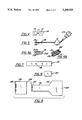
- FIG. 1A is a perspective view of a sensor probe according to the invention for adult use with release tapes removed to show a slide which facilitates insertion of the patient's finger into the probe;
- FIG. 1B is the same view as FIG. 1A, showing release tapes adhered to the inner surface of the probe;
- FIG. 2 is an exploded view of the probe shown in FIG. 1B;
- FIGS. 3A and 3B are plan and side views, respectively, of the outer tape shown in FIGS. 1A, 1B and 2;
- FIG. 4 is a plan view of the light block tape shown in FIG. 2;
- FIG. 5 is a plan view of the sensor assembly shown in FIG. 2;
- FIG. 6A is a side view of the alignment member shown in FIG. 2;
- FIG. 6B is a perspective view of an alternative embodiment of an alignment member of the invention.
- FIG. 7 is a plan view of the inner tape shown in FIG. 2;
- FIG. 8 is a plan view of the positioning slide shown in FIG. 2;
- FIG. 9 is a plan view of the release tape assembly shown in FIGS. 1B and 2;
- FIG. 10 is an exploded, cross-sectional view taken along line X--X in FIG. 1B;
- FIG. 11 is a perspective view of a probe according to the preferred embodiment of the present invention.
- FIG. 12 is an exploded, perspective view of the probe shown in FIG. 11;
- FIG. 13 is a longitudinal sectional view of the probe shown in FIG. 11 taken along line 13--13.
- a generally U-shaped probe 10 includes a web-like support structure 11 (including an outer tape 12, a light block tape 14, and other components as described below), an electrical sensor assembly 16, an alignment member 18, an inner tape 20, a positioning slide 22, and a release tape assembly 24.
- a web-like support structure 11 including an outer tape 12, a light block tape 14, and other components as described below
- an electrical sensor assembly 16 includes an alignment member 18, an inner tape 20, a positioning slide 22, and a release tape assembly 24.
- the foregoing components are sequentially assembled, such as shown in FIG. 2, into the U-shaped sensor shown in FIG. 1B.
- outer tape 12 has a pair of laterally extending, generally rectangular bottom wings 26 at one end thereof, a similar, slightly shorter pair of lateral top wings 28 at the other end thereof, and a narrow bridging portion (bight) 30 therebetween.
- the words "Top”, “Bottom”, and “Adult” and other suitable symbols may be printed on an outer surface 32 of tape 12 to aid in the identification of the probe and to facilitate application to a patient.
- Tape 12 has an inner surface including a lower inner surface 34 and an upper inner surface 35 which are spaced from each other. Inner surfaces 34, 35 of outer tape 12 are coated with a pressure sensitive adhesive at wings 26, 28 for securing probe 10 to the skin.
- Outer tape 12 is preferably made from an opaque microfoam material, for example, Stock No. 977L, manufactured by the 3M Company of St. Paul, Minn.
- light block tape 14 preferably adhesive-coated on both sides, may be made from a material known in the industry as Kodak Optical Flat Black.
- light block 14 comprises a pair of flat, preferably square end portions 15 spanned by a narrow central connecting portion 17.
- portion 17 is omitted, and opposed, flat plates 15 comprise separate pieces.
- At least one side of light block tape 14 bears a black light block layer (e.g., Coating Sciences #S121).
- Light block tape 14 of smaller dimensions than outer tape 12, overlies a portion of lower inner surface 34 of outer tape 12 and isolates the transilluminated tissue from extraneous light sources (e.g., room lighting, sunlight, etc.), thereby improving the signal-to-noise ratio of probe 10.
- extraneous light sources e.g., room lighting, sunlight, etc.
- Sensor assembly 16 shown in FIG. 5, includes a miniature light-emitting diode (LED) 36, a miniature photoreceptor (photosensor) 38, and lead wires 40 connecting the LED 36 and photosensor 38 to a cable 42.
- a 9-pin plug connector 44 attached to the other end of the cable 42, is configured to interface with a conventional oximeter box (not shown).
- Sensor assembly 16 is adhesively secured to light block tape 14 with LED 36 and photosensor 38 disposed at the center of each of square end portions 15 (see FIG. 10) and wires 40 extending along connecting portion 17.
- Inner tape 20 preferably adhesive coated on both sides, secures assembly 16 and alignment member 18 to outer tape 12.
- Inner tape 20 includes respective spaced windows 46 of transparent plastic (FIG. 7) positioned over and in registration with each of LED 36 and photosensor 38.
- Inner tape 20 is preferably opaque other than at windows 46, and may comprise one tape as shown or three pieces of tape overlying one another, e.g., one at each ends and a central tape having windows 46 overlying the ends of the other two.
- U-shaped alignment member 18 is disposed between light block tape 14 and inner tape 20 to maintain the overall configuration of the device, and particularly to maintain alignment between the LED and photosensor.
- member 18 is a thin, resilient, flat, elongated (generally rectangular) piece of plastic having a central slot or gap 19 which extends more than half the length of member 18.
- LED 36 and photosensor 38 are positioned within slot 19 near opposite ends thereof.
- Parallel rod portions 21 of member 18 on either side of slot 19 preform probe 10 into a U-shaped configuration which renders probe 10 easier to mount on a human extremity, particularly a finger.
- Rods 21 each have curved, preferably semicircular bight portions 21A (FIG.
- an alignment member 18A is fashioned in a bent U-shape with only one curved end connecting portion 23, rather than two end portions as shown in FIG. 2.
- Alignment member 18 or 18A is preferably made from a lightweight, shape-retentive polypropylene such as FINA 3622 manufactured by the Fina Oil and Chemical Company of Dallas, Tex. Alignment member 18 or 18A is preferably highly resilient, i.e., sufficiently resilient so that alignment member 18 can assume a substantially planar configuration without breaking during assembly of probe 10. When the fully assembled probe 10 is removed from the assembly tooling, alignment member 18 or 18A instantly snaps back to its overall U-shaped configuration. By means of the shape memory of member 18 or 18A, probe 10 assumes a corresponding U-shaped configuration when undeformed, as shown in FIG. 1B.
- a lightweight, shape-retentive polypropylene such as FINA 3622 manufactured by the Fina Oil and Chemical Company of Dallas, Tex.
- Alignment member 18 or 18A is preferably highly resilient, i.e., sufficiently resilient so that alignment member 18 can assume a substantially planar configuration without breaking during assembly of probe 10. When the fully assembled probe 10 is removed from the assembly tooling, alignment member
- positioning slide 22 comprises a rectangular piece of a smooth-surfaced plastic tape free of adhesive on its outer surface. Slide 22 is disposed on adhesive-coated lower inner surface 34 of outer tape 12 covering cable 42. In this way, the inner rectangular region of lower surface 34 defined by the positioning slide 22 remains adhesive-free, thus permitting the patient's finger to move freely along the positioning slide 22 until the finger abuts the bottom U-shaped end of probe 10. This reduces the risk that the sensor will stick to the patient before the LED 36 and photosensor 38 can be properly aligned.
- release tape assembly 24 includes release tapes 50 and 52 configured to releasably adhere to the inside surface of probe 10. More particularly, release tape 50 overlies bottom wings 26 of outer tape 12, concealing positioning slide 22 and portions of inner tape 20, electrical assembly 16, alignment member 18, and light block 14. Tape 52 comprises an enlarged end portion 54 and a pull tab 56. End portion 54 overlies top wings 28 of outer tape 12 and conceals the remaining portion of the inside surface of the probe. Pull tab 56 extends freely over release tape 50. Release tape assembly 24 thus protects the adhesive surfaces of probe 10 until it is ready for use.
- probe 10 To apply probe 10 to a patient, the user first pulls upon the end 55 of pull tab 56 to remove release tape 52 and fully expose release tape 50. Release tape 50 is then removed by pulling up its outer edge 58, exposing lower inner surface 34 of outer tape 12 and the various subcomponents, all of which are adhesive-coated except for the central, adhesive-free area defined by positioning slide 22 on lower inner surface 34. The patient's finger is then guided along positioning slide 22, passing through an imaginary line between LED 36 and photosensor 38, until the finger abuts the closed, U-shaped, inner end 60 of probe 10.
- alignment member 18 ensures proper alignment of the patient's finger, LED 36, and photosensor 38 without the need for the user to manually align the LED and photosensor.
- Oximeter probes according to the present invention are preferably made in sizes for adult, pediatric, infant and neonatal use.
- Probe 100 generally comprises a molded, flexible chassis 102, an electrical sensor assembly 104, and a winged backing 106.
- the chassis 102 is preferably a unitary component formed by injection molding, and has first and second widened ends 114 connected by a flexible bridge 116.
- the chassis 102 has two windows 112, one in each of the widened ends 114.
- Chassis 102 has a nonadhesive, opaque topside 108 and an underside 110.
- the topside 108 of the widened ends 114 of the chassis 102 define finger location saddles 118.
- the finger location saddles 118 are concave and extend from the outer edge of the widened ends 114 to the bridge 116.
- the windows 112 are within the finger location saddles 118.
- bridge 116 is may be folded in a U-shape to cause the windows 112 and the finger location saddles 118 to face each other.
- the underside 110 of the chassis 102 has a cavity 120 for receiving the flexible sensor assembly 104.
- chassis 102 is held topside 108 down allowing the underside 110 of the chassis 102 to act as a fixture for the assembly of the sensor assembly 104.
- the sensor assembly 104 may be secured in the cavity 120 by tape (not shown) or, preferably, the sensor assembly 104 may be molded into the chassis 102 itself.
- the flexible sensor assembly 104 contains an LED 122 and a photosensor 124. LED 122 and photosensor 124 are spaced to align with windows 112 when the electrical sensor assembly 104 is inserted into cavity 120 on chassis 102.
- Backing 106 is preferably made of die-cut foam and has a front end 126 connected to a back end 128 by a neck 130. Two opposing wings 134 extend laterally from the back end 128 of the backing 106.
- the backing 106 has an adhesive topside 132 which, on the wings 134, is covered by release tabs 138.
- the adhesive topside 132 of the backing 106 is disposed to adhere to the underside 110 of the chassis 102 over cavity 120 to capture the electrical sensor assembly 104 between the backing 106 and the chassis 102.
- the user first places one side of a finger of the patient in one of the finger location saddles 118.
- the flexible bridge 116 is bent in a U-shape around the extremity of the finger to locate the other side of the patient's finger in the other one of the finger location saddles 118.
- the finger location saddles 118 conform to the curvature of the patient's finger and serve both to properly position the finger relative to electrical sensor assembly 104 within the probe 100, and to create a snug interface between the probe 100 and the tissue of the finger to better isolate the tissue from extraneous light sources.
- one of the release tabs 138 is removed to expose the adhesive top side of a first one of the wings 134.
- the first one of the wings 134 is then folded around the side of the patient's finger and adhesively bonded to bottom side of the front end 126 of the backing 106.
- the other of the release tabs 138 is then removed to expose the adhesive top side of the second of the wings 134.
- the second of the wings 134 is similarly folded around the other side of the patient's finger and adhesively bonded to the backside of the first wing. Because the release tabs 138 need not be removed from the wings 134 until the patient's finger is already properly positioned in the probe 100, the possibility of inadvertent bonding to the patient, to the probe 100 itself, or to any other contact surface is significantly reduced.
- probe 100 may be removed and repositioned on a patient's finger since the adhesive never touches the skin of the patient.
- probe 100 may further comprise a resilient U-shaped alignment member similar to the alignment member 18 shown in FIGS. 2, 6A and 6B.
- the curved portion of the alignment member would be disposed adjacent to the flexible bridge 116 to impart a U-shape thereto, thus alleviating the need for the step of bending the flexible bridge 116 around the finger of the patient in the application procedure.
- the alignment member would further ensure that proper alignment is maintained between the LED 122 and photosensor 124.
Abstract
Description
Claims (14)
Priority Applications (1)
| Application Number | Priority Date | Filing Date | Title |
|---|---|---|---|
| US08/036,825 US5368025A (en) | 1991-08-22 | 1993-03-25 | Non-invasive oximeter probe |
Applications Claiming Priority (2)
| Application Number | Priority Date | Filing Date | Title |
|---|---|---|---|
| US07/748,700 US5217012A (en) | 1991-08-22 | 1991-08-22 | Noninvasive oximeter probe |
| US08/036,825 US5368025A (en) | 1991-08-22 | 1993-03-25 | Non-invasive oximeter probe |
Related Parent Applications (1)
| Application Number | Title | Priority Date | Filing Date |
|---|---|---|---|
| US07/748,700 Continuation-In-Part US5217012A (en) | 1991-08-22 | 1991-08-22 | Noninvasive oximeter probe |
Publications (1)
| Publication Number | Publication Date |
|---|---|
| US5368025A true US5368025A (en) | 1994-11-29 |
Family
ID=46247234
Family Applications (1)
| Application Number | Title | Priority Date | Filing Date |
|---|---|---|---|
| US08/036,825 Expired - Lifetime US5368025A (en) | 1991-08-22 | 1993-03-25 | Non-invasive oximeter probe |
Country Status (1)
| Country | Link |
|---|---|
| US (1) | US5368025A (en) |
Cited By (102)
| Publication number | Priority date | Publication date | Assignee | Title |
|---|---|---|---|---|
| US5810724A (en) * | 1995-12-01 | 1998-09-22 | Nellcor Puritan Bennett Incorporated | Reusable sensor accessory containing a conformable spring activated rubber sleeved clip |
| US6061584A (en) * | 1998-10-28 | 2000-05-09 | Lovejoy; David A. | Pulse oximetry sensor |
| US6253097B1 (en) * | 1996-03-06 | 2001-06-26 | Datex-Ohmeda, Inc. | Noninvasive medical monitoring instrument using surface emitting laser devices |
| US6353750B1 (en) * | 1997-06-27 | 2002-03-05 | Sysmex Corporation | Living body inspecting apparatus and noninvasive blood analyzer using the same |
| US6385821B1 (en) | 2000-02-17 | 2002-05-14 | Udt Sensors, Inc. | Apparatus for securing an oximeter probe to a patient |
| US6430423B2 (en) * | 1996-03-05 | 2002-08-06 | Nellcor Puritan Bennett Incorporated | Shunt barrier in pulse oximeter sensor |
| US6546267B1 (en) * | 1999-11-26 | 2003-04-08 | Nihon Kohden Corporation | Biological sensor |
| US6622034B1 (en) | 1999-09-10 | 2003-09-16 | Imagenix, Inc. | Oximeter sensor with functional liner |
| US20040134941A1 (en) * | 2002-02-12 | 2004-07-15 | Rodney Laible | Dosing and/or dispensing system |
| US20040164104A1 (en) * | 2002-02-12 | 2004-08-26 | Rodney Laible | Dosing and/or dispensing system |
| US20040204635A1 (en) * | 2003-04-10 | 2004-10-14 | Scharf Tom D. | Devices and methods for the annotation of physiological data with associated observational data |
| US20040206786A1 (en) * | 2002-02-12 | 2004-10-21 | Rodney Laible | Dosing and/or dispensing system |
| US6839584B2 (en) * | 2000-05-02 | 2005-01-04 | Instrumentation Metrics, Inc. | Method and apparatus for minimizing spectral interference due to within and between sample variations during in-situ spectral sampling of tissue |
| US6923345B1 (en) | 2002-02-12 | 2005-08-02 | Rodney Laible | Dispensing system |
| US20050197548A1 (en) * | 2004-03-05 | 2005-09-08 | Elekon Industries Usa, Inc. | Disposable/reusable flexible sensor |
| US20070015982A1 (en) * | 1996-03-05 | 2007-01-18 | Russ Delonzor | Shunt barrier in pulse oximeter sensor |
| US7647084B2 (en) | 2005-08-08 | 2010-01-12 | Nellcor Puritan Bennett Llc | Medical sensor and technique for using the same |
| US7650177B2 (en) | 2005-09-29 | 2010-01-19 | Nellcor Puritan Bennett Llc | Medical sensor for reducing motion artifacts and technique for using the same |
| US7657296B2 (en) | 2005-08-08 | 2010-02-02 | Nellcor Puritan Bennett Llc | Unitary medical sensor assembly and technique for using the same |
| US7657295B2 (en) | 2005-08-08 | 2010-02-02 | Nellcor Puritan Bennett Llc | Medical sensor and technique for using the same |
| US7658652B2 (en) | 2006-09-29 | 2010-02-09 | Nellcor Puritan Bennett Llc | Device and method for reducing crosstalk |
| US7676253B2 (en) | 2005-09-29 | 2010-03-09 | Nellcor Puritan Bennett Llc | Medical sensor and technique for using the same |
| US7680522B2 (en) | 2006-09-29 | 2010-03-16 | Nellcor Puritan Bennett Llc | Method and apparatus for detecting misapplied sensors |
| US7684842B2 (en) | 2006-09-29 | 2010-03-23 | Nellcor Puritan Bennett Llc | System and method for preventing sensor misuse |
| US7689259B2 (en) | 2000-04-17 | 2010-03-30 | Nellcor Puritan Bennett Llc | Pulse oximeter sensor with piece-wise function |
| US20100081904A1 (en) * | 2008-09-30 | 2010-04-01 | Nellcor Puritan Bennett Llc | Device And Method For Securing A Medical Sensor to An Infant's Head |
| US7698909B2 (en) | 2002-10-01 | 2010-04-20 | Nellcor Puritan Bennett Llc | Headband with tension indicator |
| US7796403B2 (en) | 2006-09-28 | 2010-09-14 | Nellcor Puritan Bennett Llc | Means for mechanical registration and mechanical-electrical coupling of a faraday shield to a photodetector and an electrical circuit |
| US7809420B2 (en) | 2003-06-25 | 2010-10-05 | Nellcor Puritan Bennett Llc | Hat-based oximeter sensor |
| US7810359B2 (en) | 2002-10-01 | 2010-10-12 | Nellcor Puritan Bennett Llc | Headband with tension indicator |
| US7869849B2 (en) | 2006-09-26 | 2011-01-11 | Nellcor Puritan Bennett Llc | Opaque, electrically nonconductive region on a medical sensor |
| US7881762B2 (en) | 2005-09-30 | 2011-02-01 | Nellcor Puritan Bennett Llc | Clip-style medical sensor and technique for using the same |
| US7880884B2 (en) * | 2008-06-30 | 2011-02-01 | Nellcor Puritan Bennett Llc | System and method for coating and shielding electronic sensor components |
| US7890153B2 (en) | 2006-09-28 | 2011-02-15 | Nellcor Puritan Bennett Llc | System and method for mitigating interference in pulse oximetry |
| US7887345B2 (en) | 2008-06-30 | 2011-02-15 | Nellcor Puritan Bennett Llc | Single use connector for pulse oximetry sensors |
| US7894869B2 (en) | 2007-03-09 | 2011-02-22 | Nellcor Puritan Bennett Llc | Multiple configuration medical sensor and technique for using the same |
| US7899510B2 (en) | 2005-09-29 | 2011-03-01 | Nellcor Puritan Bennett Llc | Medical sensor and technique for using the same |
| US8062221B2 (en) | 2005-09-30 | 2011-11-22 | Nellcor Puritan Bennett Llc | Sensor for tissue gas detection and technique for using the same |
| US8068891B2 (en) | 2006-09-29 | 2011-11-29 | Nellcor Puritan Bennett Llc | Symmetric LED array for pulse oximetry |
| US8070508B2 (en) | 2007-12-31 | 2011-12-06 | Nellcor Puritan Bennett Llc | Method and apparatus for aligning and securing a cable strain relief |
| US8071935B2 (en) | 2008-06-30 | 2011-12-06 | Nellcor Puritan Bennett Llc | Optical detector with an overmolded faraday shield |
| US8073518B2 (en) | 2006-05-02 | 2011-12-06 | Nellcor Puritan Bennett Llc | Clip-style medical sensor and technique for using the same |
| US8092379B2 (en) | 2005-09-29 | 2012-01-10 | Nellcor Puritan Bennett Llc | Method and system for determining when to reposition a physiological sensor |
| US8092993B2 (en) | 2007-12-31 | 2012-01-10 | Nellcor Puritan Bennett Llc | Hydrogel thin film for use as a biosensor |
| US8112375B2 (en) | 2008-03-31 | 2012-02-07 | Nellcor Puritan Bennett Llc | Wavelength selection and outlier detection in reduced rank linear models |
| US8133176B2 (en) | 1999-04-14 | 2012-03-13 | Tyco Healthcare Group Lp | Method and circuit for indicating quality and accuracy of physiological measurements |
| US8145288B2 (en) | 2006-08-22 | 2012-03-27 | Nellcor Puritan Bennett Llc | Medical sensor for reducing signal artifacts and technique for using the same |
| US20120101342A1 (en) * | 2010-10-21 | 2012-04-26 | Duffy Thomas P | Pediatric tissue illuminator |
| US8175671B2 (en) | 2006-09-22 | 2012-05-08 | Nellcor Puritan Bennett Llc | Medical sensor for reducing signal artifacts and technique for using the same |
| US8175667B2 (en) | 2006-09-29 | 2012-05-08 | Nellcor Puritan Bennett Llc | Symmetric LED array for pulse oximetry |
| US8190225B2 (en) | 2006-09-22 | 2012-05-29 | Nellcor Puritan Bennett Llc | Medical sensor for reducing signal artifacts and technique for using the same |
| US8199007B2 (en) | 2007-12-31 | 2012-06-12 | Nellcor Puritan Bennett Llc | Flex circuit snap track for a biometric sensor |
| US8219170B2 (en) | 2006-09-20 | 2012-07-10 | Nellcor Puritan Bennett Llc | System and method for practicing spectrophotometry using light emitting nanostructure devices |
| US8221319B2 (en) | 2009-03-25 | 2012-07-17 | Nellcor Puritan Bennett Llc | Medical device for assessing intravascular blood volume and technique for using the same |
| US8224412B2 (en) | 2000-04-17 | 2012-07-17 | Nellcor Puritan Bennett Llc | Pulse oximeter sensor with piece-wise function |
| US8233954B2 (en) | 2005-09-30 | 2012-07-31 | Nellcor Puritan Bennett Llc | Mucosal sensor for the assessment of tissue and blood constituents and technique for using the same |
| US8260391B2 (en) | 2005-09-12 | 2012-09-04 | Nellcor Puritan Bennett Llc | Medical sensor for reducing motion artifacts and technique for using the same |
| US8257274B2 (en) | 2008-09-25 | 2012-09-04 | Nellcor Puritan Bennett Llc | Medical sensor and technique for using the same |
| US8265724B2 (en) | 2007-03-09 | 2012-09-11 | Nellcor Puritan Bennett Llc | Cancellation of light shunting |
| US8280469B2 (en) | 2007-03-09 | 2012-10-02 | Nellcor Puritan Bennett Llc | Method for detection of aberrant tissue spectra |
| US8311601B2 (en) | 2009-06-30 | 2012-11-13 | Nellcor Puritan Bennett Llc | Reflectance and/or transmissive pulse oximeter |
| US8315685B2 (en) | 2006-09-27 | 2012-11-20 | Nellcor Puritan Bennett Llc | Flexible medical sensor enclosure |
| US8346328B2 (en) | 2007-12-21 | 2013-01-01 | Covidien Lp | Medical sensor and technique for using the same |
| US8352004B2 (en) | 2007-12-21 | 2013-01-08 | Covidien Lp | Medical sensor and technique for using the same |
| US8352010B2 (en) | 2005-09-30 | 2013-01-08 | Covidien Lp | Folding medical sensor and technique for using the same |
| US8352009B2 (en) | 2005-09-30 | 2013-01-08 | Covidien Lp | Medical sensor and technique for using the same |
| US8364220B2 (en) | 2008-09-25 | 2013-01-29 | Covidien Lp | Medical sensor and technique for using the same |
| US8366613B2 (en) | 2007-12-26 | 2013-02-05 | Covidien Lp | LED drive circuit for pulse oximetry and method for using same |
| US8386002B2 (en) | 2005-09-30 | 2013-02-26 | Covidien Lp | Optically aligned pulse oximetry sensor and technique for using the same |
| US8391941B2 (en) | 2009-07-17 | 2013-03-05 | Covidien Lp | System and method for memory switching for multiple configuration medical sensor |
| US8396527B2 (en) | 2006-09-22 | 2013-03-12 | Covidien Lp | Medical sensor for reducing signal artifacts and technique for using the same |
| US8412297B2 (en) | 2003-10-01 | 2013-04-02 | Covidien Lp | Forehead sensor placement |
| US8417310B2 (en) | 2009-08-10 | 2013-04-09 | Covidien Lp | Digital switching in multi-site sensor |
| US8417309B2 (en) | 2008-09-30 | 2013-04-09 | Covidien Lp | Medical sensor |
| US8423112B2 (en) | 2008-09-30 | 2013-04-16 | Covidien Lp | Medical sensor and technique for using the same |
| US8428675B2 (en) | 2009-08-19 | 2013-04-23 | Covidien Lp | Nanofiber adhesives used in medical devices |
| US8433383B2 (en) | 2001-10-12 | 2013-04-30 | Covidien Lp | Stacked adhesive optical sensor |
| US8437822B2 (en) | 2008-03-28 | 2013-05-07 | Covidien Lp | System and method for estimating blood analyte concentration |
| US8442608B2 (en) | 2007-12-28 | 2013-05-14 | Covidien Lp | System and method for estimating physiological parameters by deconvolving artifacts |
| US8452366B2 (en) | 2009-03-16 | 2013-05-28 | Covidien Lp | Medical monitoring device with flexible circuitry |
| US8452364B2 (en) | 2007-12-28 | 2013-05-28 | Covidien LLP | System and method for attaching a sensor to a patient's skin |
| US8483790B2 (en) | 2002-10-18 | 2013-07-09 | Covidien Lp | Non-adhesive oximeter sensor for sensitive skin |
| US8509869B2 (en) | 2009-05-15 | 2013-08-13 | Covidien Lp | Method and apparatus for detecting and analyzing variations in a physiologic parameter |
| US8505821B2 (en) | 2009-06-30 | 2013-08-13 | Covidien Lp | System and method for providing sensor quality assurance |
| US8515515B2 (en) | 2009-03-25 | 2013-08-20 | Covidien Lp | Medical sensor with compressible light barrier and technique for using the same |
| US8532729B2 (en) | 2011-03-31 | 2013-09-10 | Covidien Lp | Moldable ear sensor |
| US8577434B2 (en) | 2007-12-27 | 2013-11-05 | Covidien Lp | Coaxial LED light sources |
| US8577435B2 (en) | 2011-03-31 | 2013-11-05 | Covidien Lp | Flexible bandage ear sensor |
| US8634891B2 (en) | 2009-05-20 | 2014-01-21 | Covidien Lp | Method and system for self regulation of sensor component contact pressure |
| US8649839B2 (en) | 1996-10-10 | 2014-02-11 | Covidien Lp | Motion compatible sensor for non-invasive optical blood analysis |
| US8768426B2 (en) | 2011-03-31 | 2014-07-01 | Covidien Lp | Y-shaped ear sensor with strain relief |
| US8781548B2 (en) | 2009-03-31 | 2014-07-15 | Covidien Lp | Medical sensor with flexible components and technique for using the same |
| US8897850B2 (en) | 2007-12-31 | 2014-11-25 | Covidien Lp | Sensor with integrated living hinge and spring |
| US8914088B2 (en) | 2008-09-30 | 2014-12-16 | Covidien Lp | Medical sensor and technique for using the same |
| US9010634B2 (en) | 2009-06-30 | 2015-04-21 | Covidien Lp | System and method for linking patient data to a patient and providing sensor quality assurance |
| US9023314B2 (en) | 2008-09-30 | 2015-05-05 | Covidien Lp | Surface treatment for a medical device |
| US10143423B2 (en) | 2014-11-21 | 2018-12-04 | Elwha Llc | Systems to monitor body portions for injury after impact |
| US20190274606A1 (en) * | 2009-07-29 | 2019-09-12 | Masimo Corporation | Non-invasive physiological sensor cover |
| EP3545826A1 (en) * | 2018-03-30 | 2019-10-02 | Nihon Kohden Corporation | Support tool |
| US10512420B2 (en) | 2014-11-21 | 2019-12-24 | Elwha Llc | Systems to monitor body portions for injury after impact |
| US10646144B2 (en) * | 2015-12-07 | 2020-05-12 | Marcelo Malini Lamego | Wireless, disposable, extended use pulse oximeter apparatus and methods |
| US10659963B1 (en) * | 2018-02-12 | 2020-05-19 | True Wearables, Inc. | Single use medical device apparatus and methods |
Citations (13)
| Publication number | Priority date | Publication date | Assignee | Title |
|---|---|---|---|---|
| US3599629A (en) * | 1968-08-28 | 1971-08-17 | Lexington Instr | Oxidized surface biopotential skin electrode |
| US3769974A (en) * | 1971-06-29 | 1973-11-06 | Martin Marietta Corp | Blood pulse measuring employing reflected red light |
| US4091803A (en) * | 1975-02-17 | 1978-05-30 | Thomas Orr | Transducers |
| US4350165A (en) * | 1980-05-23 | 1982-09-21 | Trw Inc. | Medical electrode assembly |
| US4685464A (en) * | 1985-07-05 | 1987-08-11 | Nellcor Incorporated | Durable sensor for detecting optical pulses |
| US4830014A (en) * | 1983-05-11 | 1989-05-16 | Nellcor Incorporated | Sensor having cutaneous conformance |
| US4865038A (en) * | 1986-10-09 | 1989-09-12 | Novametrix Medical Systems, Inc. | Sensor appliance for non-invasive monitoring |
| US4867165A (en) * | 1987-06-03 | 1989-09-19 | Hewlett-Packard Company | Method for determining the perfusion |
| US4974591A (en) * | 1987-11-02 | 1990-12-04 | Sumitomo Electric Industries, Ltd. | Bio-photosensor |
| US5035243A (en) * | 1988-03-26 | 1991-07-30 | Nicolay Gmbh | Holder sleeve for positioning a detecting and measuring sensor |
| US5054488A (en) * | 1989-04-20 | 1991-10-08 | Nicolay Gmbh | Optoelectronic sensor for producing electrical signals representative of physiological values |
| US5058588A (en) * | 1989-09-19 | 1991-10-22 | Hewlett-Packard Company | Oximeter and medical sensor therefor |
| US5209230A (en) * | 1990-10-19 | 1993-05-11 | Nellcor Incorporated | Adhesive pulse oximeter sensor with reusable portion |
-
1993
- 1993-03-25 US US08/036,825 patent/US5368025A/en not_active Expired - Lifetime
Patent Citations (13)
| Publication number | Priority date | Publication date | Assignee | Title |
|---|---|---|---|---|
| US3599629A (en) * | 1968-08-28 | 1971-08-17 | Lexington Instr | Oxidized surface biopotential skin electrode |
| US3769974A (en) * | 1971-06-29 | 1973-11-06 | Martin Marietta Corp | Blood pulse measuring employing reflected red light |
| US4091803A (en) * | 1975-02-17 | 1978-05-30 | Thomas Orr | Transducers |
| US4350165A (en) * | 1980-05-23 | 1982-09-21 | Trw Inc. | Medical electrode assembly |
| US4830014A (en) * | 1983-05-11 | 1989-05-16 | Nellcor Incorporated | Sensor having cutaneous conformance |
| US4685464A (en) * | 1985-07-05 | 1987-08-11 | Nellcor Incorporated | Durable sensor for detecting optical pulses |
| US4865038A (en) * | 1986-10-09 | 1989-09-12 | Novametrix Medical Systems, Inc. | Sensor appliance for non-invasive monitoring |
| US4867165A (en) * | 1987-06-03 | 1989-09-19 | Hewlett-Packard Company | Method for determining the perfusion |
| US4974591A (en) * | 1987-11-02 | 1990-12-04 | Sumitomo Electric Industries, Ltd. | Bio-photosensor |
| US5035243A (en) * | 1988-03-26 | 1991-07-30 | Nicolay Gmbh | Holder sleeve for positioning a detecting and measuring sensor |
| US5054488A (en) * | 1989-04-20 | 1991-10-08 | Nicolay Gmbh | Optoelectronic sensor for producing electrical signals representative of physiological values |
| US5058588A (en) * | 1989-09-19 | 1991-10-22 | Hewlett-Packard Company | Oximeter and medical sensor therefor |
| US5209230A (en) * | 1990-10-19 | 1993-05-11 | Nellcor Incorporated | Adhesive pulse oximeter sensor with reusable portion |
Cited By (164)
| Publication number | Priority date | Publication date | Assignee | Title |
|---|---|---|---|---|
| US5810724A (en) * | 1995-12-01 | 1998-09-22 | Nellcor Puritan Bennett Incorporated | Reusable sensor accessory containing a conformable spring activated rubber sleeved clip |
| US7373190B2 (en) | 1996-03-05 | 2008-05-13 | Nellcor Puritan Bennett Inc. | Shunt barrier in pulse oximeter sensor |
| US7418284B2 (en) | 1996-03-05 | 2008-08-26 | Nellcor Puritan Bennett Inc. | Shunt barrier in pulse oximeter sensor |
| US7321790B2 (en) | 1996-03-05 | 2008-01-22 | Nellcor Puritan Bennett Incorporated | Shunt barrier in pulse oximeter sensor |
| US20070021661A1 (en) * | 1996-03-05 | 2007-01-25 | Russ Delonzor | Shunt barrier in pulse oximeter sensor |
| US6430423B2 (en) * | 1996-03-05 | 2002-08-06 | Nellcor Puritan Bennett Incorporated | Shunt barrier in pulse oximeter sensor |
| US20020173708A1 (en) * | 1996-03-05 | 2002-11-21 | Nellcor Puritan Bennett Incorporated | Shunt barrier in pulse oximeter sensor |
| US7190984B1 (en) * | 1996-03-05 | 2007-03-13 | Nellcor Puritan Bennett Incorporated | Shunt barrier in pulse oximeter sensor |
| US20070027379A1 (en) * | 1996-03-05 | 2007-02-01 | Russ Delonzor | Shunt barrier in pulse oximeter sensor |
| US20070027380A1 (en) * | 1996-03-05 | 2007-02-01 | Delonzar Russ | Shunt barrier in pulse oximeter sensor |
| US6763255B2 (en) * | 1996-03-05 | 2004-07-13 | Nellcor Puritan Bennett Incorporated | Shunt barrier in pulse oximeter sensor |
| US20070021662A1 (en) * | 1996-03-05 | 2007-01-25 | Russ Delonzor | Shunt barrier in pulse oximeter sensor |
| US7561905B2 (en) | 1996-03-05 | 2009-07-14 | Nellcor Puritan Bennet LLC | Shunt barrier in pulse oximeter sensor |
| US20070021663A1 (en) * | 1996-03-05 | 2007-01-25 | Russ Delonzor | Shunt barrier in pulse oximeter sensor |
| US20070027378A1 (en) * | 1996-03-05 | 2007-02-01 | Russ Delonzor | Shunt barrier in pulse oximeter sensor |
| US7389130B2 (en) | 1996-03-05 | 2008-06-17 | Nellcor Puritan Bennett Inc. | Shunt barrier in pulse oximeter sensor |
| US7386334B2 (en) | 1996-03-05 | 2008-06-10 | Nellcor Puritan Bennett Inc. | Shunt barrier in pulse oximeter sensor |
| US20070027377A1 (en) * | 1996-03-05 | 2007-02-01 | Russ Delonzor | Shunt barrier in pulse oximeter sensor |
| US7373189B2 (en) | 1996-03-05 | 2008-05-13 | Nellcor Puritan Bennett Inc. | Shunt barrier in pulse oximeter sensor |
| US7373191B2 (en) | 1996-03-05 | 2008-05-13 | Nellcor Puritan Bennett Inc. | Shunt barrier in pulse oximeter sensor |
| US20070015982A1 (en) * | 1996-03-05 | 2007-01-18 | Russ Delonzor | Shunt barrier in pulse oximeter sensor |
| US7373188B2 (en) | 1996-03-05 | 2008-05-13 | Nellcor Puritan Bennett Inc. | Shunt barrier in pulse oximeter sensor |
| US20070021659A1 (en) * | 1996-03-05 | 2007-01-25 | Russ Delonzor | Shunt barrier in pulse oximeter sensor |
| US7369886B2 (en) | 1996-03-05 | 2008-05-06 | Nellcor Puritan Bennett Inc. | Shunt barrier in pulse oximeter sensor |
| US20070021660A1 (en) * | 1996-03-05 | 2007-01-25 | Russ Delonzor | Shunt barrier in pulse oximeter sensor |
| US6253097B1 (en) * | 1996-03-06 | 2001-06-26 | Datex-Ohmeda, Inc. | Noninvasive medical monitoring instrument using surface emitting laser devices |
| US8649839B2 (en) | 1996-10-10 | 2014-02-11 | Covidien Lp | Motion compatible sensor for non-invasive optical blood analysis |
| US6353750B1 (en) * | 1997-06-27 | 2002-03-05 | Sysmex Corporation | Living body inspecting apparatus and noninvasive blood analyzer using the same |
| US6061584A (en) * | 1998-10-28 | 2000-05-09 | Lovejoy; David A. | Pulse oximetry sensor |
| US8133176B2 (en) | 1999-04-14 | 2012-03-13 | Tyco Healthcare Group Lp | Method and circuit for indicating quality and accuracy of physiological measurements |
| US6622034B1 (en) | 1999-09-10 | 2003-09-16 | Imagenix, Inc. | Oximeter sensor with functional liner |
| US6546267B1 (en) * | 1999-11-26 | 2003-04-08 | Nihon Kohden Corporation | Biological sensor |
| US6385821B1 (en) | 2000-02-17 | 2002-05-14 | Udt Sensors, Inc. | Apparatus for securing an oximeter probe to a patient |
| US6681454B2 (en) | 2000-02-17 | 2004-01-27 | Udt Sensors, Inc. | Apparatus and method for securing an oximeter probe to a patient |
| US8078246B2 (en) | 2000-04-17 | 2011-12-13 | Nellcor Puritan Bennett Llc | Pulse oximeter sensor with piece-wise function |
| US8224412B2 (en) | 2000-04-17 | 2012-07-17 | Nellcor Puritan Bennett Llc | Pulse oximeter sensor with piece-wise function |
| US7689259B2 (en) | 2000-04-17 | 2010-03-30 | Nellcor Puritan Bennett Llc | Pulse oximeter sensor with piece-wise function |
| US6839584B2 (en) * | 2000-05-02 | 2005-01-04 | Instrumentation Metrics, Inc. | Method and apparatus for minimizing spectral interference due to within and between sample variations during in-situ spectral sampling of tissue |
| US8433383B2 (en) | 2001-10-12 | 2013-04-30 | Covidien Lp | Stacked adhesive optical sensor |
| US20040134941A1 (en) * | 2002-02-12 | 2004-07-15 | Rodney Laible | Dosing and/or dispensing system |
| US6986443B2 (en) | 2002-02-12 | 2006-01-17 | Rodney Laible | Dosing and/or dispensing system |
| US6945432B2 (en) | 2002-02-12 | 2005-09-20 | Rodney Laible | Dosing and/or dispensing system |
| US6923345B1 (en) | 2002-02-12 | 2005-08-02 | Rodney Laible | Dispensing system |
| US20040206786A1 (en) * | 2002-02-12 | 2004-10-21 | Rodney Laible | Dosing and/or dispensing system |
| US20040164104A1 (en) * | 2002-02-12 | 2004-08-26 | Rodney Laible | Dosing and/or dispensing system |
| US7822453B2 (en) | 2002-10-01 | 2010-10-26 | Nellcor Puritan Bennett Llc | Forehead sensor placement |
| US7698909B2 (en) | 2002-10-01 | 2010-04-20 | Nellcor Puritan Bennett Llc | Headband with tension indicator |
| US8452367B2 (en) | 2002-10-01 | 2013-05-28 | Covidien Lp | Forehead sensor placement |
| US7810359B2 (en) | 2002-10-01 | 2010-10-12 | Nellcor Puritan Bennett Llc | Headband with tension indicator |
| US7899509B2 (en) | 2002-10-01 | 2011-03-01 | Nellcor Puritan Bennett Llc | Forehead sensor placement |
| US8483790B2 (en) | 2002-10-18 | 2013-07-09 | Covidien Lp | Non-adhesive oximeter sensor for sensitive skin |
| US20040204635A1 (en) * | 2003-04-10 | 2004-10-14 | Scharf Tom D. | Devices and methods for the annotation of physiological data with associated observational data |
| US7813779B2 (en) | 2003-06-25 | 2010-10-12 | Nellcor Puritan Bennett Llc | Hat-based oximeter sensor |
| US7979102B2 (en) | 2003-06-25 | 2011-07-12 | Nellcor Puritan Bennett Llc | Hat-based oximeter sensor |
| US7877127B2 (en) | 2003-06-25 | 2011-01-25 | Nellcor Puritan Bennett Llc | Hat-based oximeter sensor |
| US7809420B2 (en) | 2003-06-25 | 2010-10-05 | Nellcor Puritan Bennett Llc | Hat-based oximeter sensor |
| US7877126B2 (en) | 2003-06-25 | 2011-01-25 | Nellcor Puritan Bennett Llc | Hat-based oximeter sensor |
| US8412297B2 (en) | 2003-10-01 | 2013-04-02 | Covidien Lp | Forehead sensor placement |
| US20050197548A1 (en) * | 2004-03-05 | 2005-09-08 | Elekon Industries Usa, Inc. | Disposable/reusable flexible sensor |
| US7657295B2 (en) | 2005-08-08 | 2010-02-02 | Nellcor Puritan Bennett Llc | Medical sensor and technique for using the same |
| US7738937B2 (en) | 2005-08-08 | 2010-06-15 | Nellcor Puritan Bennett Llc | Medical sensor and technique for using the same |
| US7647084B2 (en) | 2005-08-08 | 2010-01-12 | Nellcor Puritan Bennett Llc | Medical sensor and technique for using the same |
| US7657296B2 (en) | 2005-08-08 | 2010-02-02 | Nellcor Puritan Bennett Llc | Unitary medical sensor assembly and technique for using the same |
| US7693559B2 (en) | 2005-08-08 | 2010-04-06 | Nellcor Puritan Bennett Llc | Medical sensor having a deformable region and technique for using the same |
| US8528185B2 (en) | 2005-08-08 | 2013-09-10 | Covidien Lp | Bi-stable medical sensor and technique for using the same |
| US7684843B2 (en) | 2005-08-08 | 2010-03-23 | Nellcor Puritan Bennett Llc | Medical sensor and technique for using the same |
| US8311602B2 (en) | 2005-08-08 | 2012-11-13 | Nellcor Puritan Bennett Llc | Compliant diaphragm medical sensor and technique for using the same |
| US7657294B2 (en) | 2005-08-08 | 2010-02-02 | Nellcor Puritan Bennett Llc | Compliant diaphragm medical sensor and technique for using the same |
| US8260391B2 (en) | 2005-09-12 | 2012-09-04 | Nellcor Puritan Bennett Llc | Medical sensor for reducing motion artifacts and technique for using the same |
| US7729736B2 (en) | 2005-09-29 | 2010-06-01 | Nellcor Puritan Bennett Llc | Medical sensor and technique for using the same |
| US7650177B2 (en) | 2005-09-29 | 2010-01-19 | Nellcor Puritan Bennett Llc | Medical sensor for reducing motion artifacts and technique for using the same |
| US8092379B2 (en) | 2005-09-29 | 2012-01-10 | Nellcor Puritan Bennett Llc | Method and system for determining when to reposition a physiological sensor |
| US7899510B2 (en) | 2005-09-29 | 2011-03-01 | Nellcor Puritan Bennett Llc | Medical sensor and technique for using the same |
| US7676253B2 (en) | 2005-09-29 | 2010-03-09 | Nellcor Puritan Bennett Llc | Medical sensor and technique for using the same |
| US7904130B2 (en) | 2005-09-29 | 2011-03-08 | Nellcor Puritan Bennett Llc | Medical sensor and technique for using the same |
| US8600469B2 (en) | 2005-09-29 | 2013-12-03 | Covidien Lp | Medical sensor and technique for using the same |
| US7869850B2 (en) | 2005-09-29 | 2011-01-11 | Nellcor Puritan Bennett Llc | Medical sensor for reducing motion artifacts and technique for using the same |
| US8060171B2 (en) | 2005-09-29 | 2011-11-15 | Nellcor Puritan Bennett Llc | Medical sensor for reducing motion artifacts and technique for using the same |
| US8965473B2 (en) | 2005-09-29 | 2015-02-24 | Covidien Lp | Medical sensor for reducing motion artifacts and technique for using the same |
| US8352009B2 (en) | 2005-09-30 | 2013-01-08 | Covidien Lp | Medical sensor and technique for using the same |
| US8233954B2 (en) | 2005-09-30 | 2012-07-31 | Nellcor Puritan Bennett Llc | Mucosal sensor for the assessment of tissue and blood constituents and technique for using the same |
| US8062221B2 (en) | 2005-09-30 | 2011-11-22 | Nellcor Puritan Bennett Llc | Sensor for tissue gas detection and technique for using the same |
| US7881762B2 (en) | 2005-09-30 | 2011-02-01 | Nellcor Puritan Bennett Llc | Clip-style medical sensor and technique for using the same |
| US8386002B2 (en) | 2005-09-30 | 2013-02-26 | Covidien Lp | Optically aligned pulse oximetry sensor and technique for using the same |
| US8352010B2 (en) | 2005-09-30 | 2013-01-08 | Covidien Lp | Folding medical sensor and technique for using the same |
| US8073518B2 (en) | 2006-05-02 | 2011-12-06 | Nellcor Puritan Bennett Llc | Clip-style medical sensor and technique for using the same |
| US8437826B2 (en) | 2006-05-02 | 2013-05-07 | Covidien Lp | Clip-style medical sensor and technique for using the same |
| US8145288B2 (en) | 2006-08-22 | 2012-03-27 | Nellcor Puritan Bennett Llc | Medical sensor for reducing signal artifacts and technique for using the same |
| US8577436B2 (en) | 2006-08-22 | 2013-11-05 | Covidien Lp | Medical sensor for reducing signal artifacts and technique for using the same |
| US8219170B2 (en) | 2006-09-20 | 2012-07-10 | Nellcor Puritan Bennett Llc | System and method for practicing spectrophotometry using light emitting nanostructure devices |
| US8195264B2 (en) | 2006-09-22 | 2012-06-05 | Nellcor Puritan Bennett Llc | Medical sensor for reducing signal artifacts and technique for using the same |
| US8396527B2 (en) | 2006-09-22 | 2013-03-12 | Covidien Lp | Medical sensor for reducing signal artifacts and technique for using the same |
| US8175671B2 (en) | 2006-09-22 | 2012-05-08 | Nellcor Puritan Bennett Llc | Medical sensor for reducing signal artifacts and technique for using the same |
| US8190225B2 (en) | 2006-09-22 | 2012-05-29 | Nellcor Puritan Bennett Llc | Medical sensor for reducing signal artifacts and technique for using the same |
| US8190224B2 (en) | 2006-09-22 | 2012-05-29 | Nellcor Puritan Bennett Llc | Medical sensor for reducing signal artifacts and technique for using the same |
| US8515512B2 (en) | 2006-09-26 | 2013-08-20 | Covidien Lp | Opaque, electrically nonconductive region on a medical sensor |
| US7869849B2 (en) | 2006-09-26 | 2011-01-11 | Nellcor Puritan Bennett Llc | Opaque, electrically nonconductive region on a medical sensor |
| US20110066016A1 (en) * | 2006-09-26 | 2011-03-17 | Nellcor Puritan Bennett Llc | Opaque, electrically nonconductive region on a medical sensor |
| US8315685B2 (en) | 2006-09-27 | 2012-11-20 | Nellcor Puritan Bennett Llc | Flexible medical sensor enclosure |
| US7890153B2 (en) | 2006-09-28 | 2011-02-15 | Nellcor Puritan Bennett Llc | System and method for mitigating interference in pulse oximetry |
| US8660626B2 (en) | 2006-09-28 | 2014-02-25 | Covidien Lp | System and method for mitigating interference in pulse oximetry |
| US7796403B2 (en) | 2006-09-28 | 2010-09-14 | Nellcor Puritan Bennett Llc | Means for mechanical registration and mechanical-electrical coupling of a faraday shield to a photodetector and an electrical circuit |
| US7658652B2 (en) | 2006-09-29 | 2010-02-09 | Nellcor Puritan Bennett Llc | Device and method for reducing crosstalk |
| US8175667B2 (en) | 2006-09-29 | 2012-05-08 | Nellcor Puritan Bennett Llc | Symmetric LED array for pulse oximetry |
| US7680522B2 (en) | 2006-09-29 | 2010-03-16 | Nellcor Puritan Bennett Llc | Method and apparatus for detecting misapplied sensors |
| US8068891B2 (en) | 2006-09-29 | 2011-11-29 | Nellcor Puritan Bennett Llc | Symmetric LED array for pulse oximetry |
| US7684842B2 (en) | 2006-09-29 | 2010-03-23 | Nellcor Puritan Bennett Llc | System and method for preventing sensor misuse |
| US7794266B2 (en) | 2006-09-29 | 2010-09-14 | Nellcor Puritan Bennett Llc | Device and method for reducing crosstalk |
| US8280469B2 (en) | 2007-03-09 | 2012-10-02 | Nellcor Puritan Bennett Llc | Method for detection of aberrant tissue spectra |
| US7894869B2 (en) | 2007-03-09 | 2011-02-22 | Nellcor Puritan Bennett Llc | Multiple configuration medical sensor and technique for using the same |
| US8265724B2 (en) | 2007-03-09 | 2012-09-11 | Nellcor Puritan Bennett Llc | Cancellation of light shunting |
| US8352004B2 (en) | 2007-12-21 | 2013-01-08 | Covidien Lp | Medical sensor and technique for using the same |
| US8346328B2 (en) | 2007-12-21 | 2013-01-01 | Covidien Lp | Medical sensor and technique for using the same |
| US8366613B2 (en) | 2007-12-26 | 2013-02-05 | Covidien Lp | LED drive circuit for pulse oximetry and method for using same |
| US8577434B2 (en) | 2007-12-27 | 2013-11-05 | Covidien Lp | Coaxial LED light sources |
| US8442608B2 (en) | 2007-12-28 | 2013-05-14 | Covidien Lp | System and method for estimating physiological parameters by deconvolving artifacts |
| US8452364B2 (en) | 2007-12-28 | 2013-05-28 | Covidien LLP | System and method for attaching a sensor to a patient's skin |
| US8897850B2 (en) | 2007-12-31 | 2014-11-25 | Covidien Lp | Sensor with integrated living hinge and spring |
| US8070508B2 (en) | 2007-12-31 | 2011-12-06 | Nellcor Puritan Bennett Llc | Method and apparatus for aligning and securing a cable strain relief |
| US8199007B2 (en) | 2007-12-31 | 2012-06-12 | Nellcor Puritan Bennett Llc | Flex circuit snap track for a biometric sensor |
| US8092993B2 (en) | 2007-12-31 | 2012-01-10 | Nellcor Puritan Bennett Llc | Hydrogel thin film for use as a biosensor |
| US8437822B2 (en) | 2008-03-28 | 2013-05-07 | Covidien Lp | System and method for estimating blood analyte concentration |
| US8112375B2 (en) | 2008-03-31 | 2012-02-07 | Nellcor Puritan Bennett Llc | Wavelength selection and outlier detection in reduced rank linear models |
| US7880884B2 (en) * | 2008-06-30 | 2011-02-01 | Nellcor Puritan Bennett Llc | System and method for coating and shielding electronic sensor components |
| US8071935B2 (en) | 2008-06-30 | 2011-12-06 | Nellcor Puritan Bennett Llc | Optical detector with an overmolded faraday shield |
| US7887345B2 (en) | 2008-06-30 | 2011-02-15 | Nellcor Puritan Bennett Llc | Single use connector for pulse oximetry sensors |
| US8364220B2 (en) | 2008-09-25 | 2013-01-29 | Covidien Lp | Medical sensor and technique for using the same |
| US8257274B2 (en) | 2008-09-25 | 2012-09-04 | Nellcor Puritan Bennett Llc | Medical sensor and technique for using the same |
| US8417309B2 (en) | 2008-09-30 | 2013-04-09 | Covidien Lp | Medical sensor |
| US8914088B2 (en) | 2008-09-30 | 2014-12-16 | Covidien Lp | Medical sensor and technique for using the same |
| US9023314B2 (en) | 2008-09-30 | 2015-05-05 | Covidien Lp | Surface treatment for a medical device |
| US20100081904A1 (en) * | 2008-09-30 | 2010-04-01 | Nellcor Puritan Bennett Llc | Device And Method For Securing A Medical Sensor to An Infant's Head |
| US8423112B2 (en) | 2008-09-30 | 2013-04-16 | Covidien Lp | Medical sensor and technique for using the same |
| US8452366B2 (en) | 2009-03-16 | 2013-05-28 | Covidien Lp | Medical monitoring device with flexible circuitry |
| US8221319B2 (en) | 2009-03-25 | 2012-07-17 | Nellcor Puritan Bennett Llc | Medical device for assessing intravascular blood volume and technique for using the same |
| US8515515B2 (en) | 2009-03-25 | 2013-08-20 | Covidien Lp | Medical sensor with compressible light barrier and technique for using the same |
| US8781548B2 (en) | 2009-03-31 | 2014-07-15 | Covidien Lp | Medical sensor with flexible components and technique for using the same |
| US8509869B2 (en) | 2009-05-15 | 2013-08-13 | Covidien Lp | Method and apparatus for detecting and analyzing variations in a physiologic parameter |
| US8634891B2 (en) | 2009-05-20 | 2014-01-21 | Covidien Lp | Method and system for self regulation of sensor component contact pressure |
| US8505821B2 (en) | 2009-06-30 | 2013-08-13 | Covidien Lp | System and method for providing sensor quality assurance |
| US9010634B2 (en) | 2009-06-30 | 2015-04-21 | Covidien Lp | System and method for linking patient data to a patient and providing sensor quality assurance |
| US8311601B2 (en) | 2009-06-30 | 2012-11-13 | Nellcor Puritan Bennett Llc | Reflectance and/or transmissive pulse oximeter |
| US8391941B2 (en) | 2009-07-17 | 2013-03-05 | Covidien Lp | System and method for memory switching for multiple configuration medical sensor |
| US20190274606A1 (en) * | 2009-07-29 | 2019-09-12 | Masimo Corporation | Non-invasive physiological sensor cover |
| US11369293B2 (en) | 2009-07-29 | 2022-06-28 | Masimo Corporation | Non-invasive physiological sensor cover |
| US11779247B2 (en) | 2009-07-29 | 2023-10-10 | Masimo Corporation | Non-invasive physiological sensor cover |
| US11559227B2 (en) | 2009-07-29 | 2023-01-24 | Masimo Corporation | Non-invasive physiological sensor cover |
| US10478107B2 (en) * | 2009-07-29 | 2019-11-19 | Masimo Corporation | Non-invasive physiological sensor cover |
| US10588556B2 (en) | 2009-07-29 | 2020-03-17 | Masimo Corporation | Non-invasive physiological sensor cover |
| US8417310B2 (en) | 2009-08-10 | 2013-04-09 | Covidien Lp | Digital switching in multi-site sensor |
| US8428675B2 (en) | 2009-08-19 | 2013-04-23 | Covidien Lp | Nanofiber adhesives used in medical devices |
| US20120101342A1 (en) * | 2010-10-21 | 2012-04-26 | Duffy Thomas P | Pediatric tissue illuminator |
| US20120101343A1 (en) * | 2010-10-21 | 2012-04-26 | Duffy Thomas P | Medical imaging device |
| US8768426B2 (en) | 2011-03-31 | 2014-07-01 | Covidien Lp | Y-shaped ear sensor with strain relief |
| US8577435B2 (en) | 2011-03-31 | 2013-11-05 | Covidien Lp | Flexible bandage ear sensor |
| US8532729B2 (en) | 2011-03-31 | 2013-09-10 | Covidien Lp | Moldable ear sensor |
| US10512420B2 (en) | 2014-11-21 | 2019-12-24 | Elwha Llc | Systems to monitor body portions for injury after impact |
| US10143423B2 (en) | 2014-11-21 | 2018-12-04 | Elwha Llc | Systems to monitor body portions for injury after impact |
| US11109783B2 (en) | 2015-12-07 | 2021-09-07 | True Wearables, Inc. | Wireless, disposable, extended use pulse oximeter apparatus and methods |
| US10646144B2 (en) * | 2015-12-07 | 2020-05-12 | Marcelo Malini Lamego | Wireless, disposable, extended use pulse oximeter apparatus and methods |
| US11647924B2 (en) | 2015-12-07 | 2023-05-16 | True Wearables, Inc. | Wireless, disposable, extended use pulse oximeter apparatus and methods |
| US10659963B1 (en) * | 2018-02-12 | 2020-05-19 | True Wearables, Inc. | Single use medical device apparatus and methods |
| US11317283B1 (en) | 2018-02-12 | 2022-04-26 | True Wearables, Inc. | Single use medical device apparatus and methods |
| EP3545826A1 (en) * | 2018-03-30 | 2019-10-02 | Nihon Kohden Corporation | Support tool |
Similar Documents
| Publication | Publication Date | Title |
|---|---|---|
| US5368025A (en) | Non-invasive oximeter probe | |
| US5217012A (en) | Noninvasive oximeter probe | |
| US10478107B2 (en) | Non-invasive physiological sensor cover | |
| US4830014A (en) | Sensor having cutaneous conformance | |
| US5209230A (en) | Adhesive pulse oximeter sensor with reusable portion | |
| US5170786A (en) | Reusable probe system | |
| US6622034B1 (en) | Oximeter sensor with functional liner | |
| EP0127947B1 (en) | Sensor having cutaneous conformance | |
| US5999834A (en) | Disposable adhesive wrap for use with reusable pulse oximetry sensor and method of making | |
| US6671532B1 (en) | Pulse oximetry sensor and dispensing method | |
| CA2530414C (en) | Hat-based oximeter sensor | |
| US7742794B2 (en) | Probe adapted to be used with pulse oximeter | |
| JP2015534495A (en) | Monitoring device | |
| JPH0220252B2 (en) | ||
| JPS6363430A (en) | Probe for oximeter |
Legal Events
| Date | Code | Title | Description |
|---|---|---|---|
| AS | Assignment |
Owner name: SENSOR DEVICES INC., WISCONSIN Free format text: ASSIGNMENT OF ASSIGNORS INTEREST.;ASSIGNORS:YOUNG, ROBERT L.;HEINZELMAN, BERT D.;LOVEJOY, DAVID A.;REEL/FRAME:006489/0757;SIGNING DATES FROM 19930312 TO 19930323 |
|
| STPP | Information on status: patent application and granting procedure in general |
Free format text: APPLICATION UNDERGOING PREEXAM PROCESSING |
|
| AS | Assignment |
Owner name: BCI INTERNATIONAL, WISCONSIN Free format text: SECURITY AGREEMENT;ASSIGNOR:SENSOR DEVICES, INC.;REEL/FRAME:008167/0695 Effective date: 19960626 |
|
| AS | Assignment |
Owner name: PARK BANK, WISCONSIN Free format text: SECURITY AGREEMENT;ASSIGNOR:SENSOR DEVICES, INC.;REEL/FRAME:008215/0761 Effective date: 19940329 |
|
| AS | Assignment |
Owner name: SENSOR DEVICES, INC., WISCONSIN Free format text: RELEASE OF SECURITY INTEREST;ASSIGNOR:BCI INTERNATIONAL;REEL/FRAME:008470/0556 Effective date: 19970418 |
|
| FEPP | Fee payment procedure |
Free format text: PAYOR NUMBER ASSIGNED (ORIGINAL EVENT CODE: ASPN); ENTITY STATUS OF PATENT OWNER: SMALL ENTITY |
|
| FPAY | Fee payment |
Year of fee payment: 4 |
|
| AS | Assignment |
Owner name: ARISTO MEDICAL PRODUCTS, INC., CALIFORNIA Free format text: ASSIGNMENT OF ASSIGNORS INTEREST;ASSIGNOR:SENSOR DEVICES, INC.;REEL/FRAME:009808/0416 Effective date: 19990122 |
|
| FEPP | Fee payment procedure |
Free format text: PAYOR NUMBER ASSIGNED (ORIGINAL EVENT CODE: ASPN); ENTITY STATUS OF PATENT OWNER: SMALL ENTITY Free format text: PAYER NUMBER DE-ASSIGNED (ORIGINAL EVENT CODE: RMPN); ENTITY STATUS OF PATENT OWNER: SMALL ENTITY |
|
| FPAY | Fee payment |
Year of fee payment: 8 |
|
| REMI | Maintenance fee reminder mailed | ||
| AS | Assignment |
Owner name: BANK OF THE WEST, A CALIFORNIA BANKING CORPORATION Free format text: SECURITY AGREEMENT;ASSIGNOR:ARISTO MEDICAL PRODUCTS, INC.;REEL/FRAME:016182/0643 Effective date: 20050624 |
|
| FPAY | Fee payment |
Year of fee payment: 12 |
|
| REMI | Maintenance fee reminder mailed | ||
| AS | Assignment |
Owner name: WACHOVIA BANK, NATIONAL ASSOCIATION, AS ADMINISTRA Free format text: NOTICE OF GRANT OF SECURITY INTEREST;ASSIGNOR:DOLPHIN MEDICAL, INC.;REEL/FRAME:019679/0477 Effective date: 20070727 |
|
| AS | Assignment |
Owner name: DOLPHIN MEDICAL, INC., CALIFORNIA Free format text: NUNC PRO TUNC ASSIGNMENT;ASSIGNOR:ARISTO MEDICAL PRODUCTS, INC.;REEL/FRAME:020468/0446 Effective date: 20050824 |
|
| AS | Assignment |
Owner name: ARISTO MEDICAL PRODUCTS, INC., CALIFORNIA Free format text: RELEASE BY SECURED PARTY;ASSIGNOR:BANK OF THE WEST;REEL/FRAME:021109/0829 Effective date: 20080428 |
|
| AS | Assignment |
Owner name: WELLS FARGO BANK, NATIONAL ASSOCIATION, AS ADMINIS Free format text: NOTICE OF GRANT OF SECURITY INTEREST IN PATENTS;ASSIGNOR:DOLPHIN MEDICAL, INC.;REEL/FRAME:025150/0971 Effective date: 20070727 |
|
| AS | Assignment |
Owner name: DOLPHIN MEDICAL, INC., CALIFORNIA Free format text: TERMINATION OF SECURITY INTEREST IN PATENTS;ASSIGNOR:WELLS FARGO BANK, NATIONAL ASSOCIATION, SUCCESSOR-BY-MERGER TO WACHOVIA BANK, NATIONAL ASSOCIATION, AS ADMINISTRATIVE AGENT;REEL/FRAME:025169/0293 Effective date: 20101015 |