EP0314491B1 - Polarization diversity light receiving system - Google Patents
Polarization diversity light receiving system Download PDFInfo
- Publication number
- EP0314491B1 EP0314491B1 EP88310146A EP88310146A EP0314491B1 EP 0314491 B1 EP0314491 B1 EP 0314491B1 EP 88310146 A EP88310146 A EP 88310146A EP 88310146 A EP88310146 A EP 88310146A EP 0314491 B1 EP0314491 B1 EP 0314491B1
- Authority
- EP
- European Patent Office
- Prior art keywords
- light
- receiving system
- frequency
- light receiving
- polarization
- Prior art date
- Legal status (The legal status is an assumption and is not a legal conclusion. Google has not performed a legal analysis and makes no representation as to the accuracy of the status listed.)
- Expired - Lifetime
Links
Images


Classifications
-
- H—ELECTRICITY
- H04—ELECTRIC COMMUNICATION TECHNIQUE
- H04B—TRANSMISSION
- H04B10/00—Transmission systems employing electromagnetic waves other than radio-waves, e.g. infrared, visible or ultraviolet light, or employing corpuscular radiation, e.g. quantum communication
- H04B10/60—Receivers
- H04B10/61—Coherent receivers
- H04B10/614—Coherent receivers comprising one or more polarization beam splitters, e.g. polarization multiplexed [PolMux] X-PSK coherent receivers, polarization diversity heterodyne coherent receivers
-
- H—ELECTRICITY
- H04—ELECTRIC COMMUNICATION TECHNIQUE
- H04B—TRANSMISSION
- H04B10/00—Transmission systems employing electromagnetic waves other than radio-waves, e.g. infrared, visible or ultraviolet light, or employing corpuscular radiation, e.g. quantum communication
- H04B10/60—Receivers
- H04B10/61—Coherent receivers
- H04B10/64—Heterodyne, i.e. coherent receivers where, after the opto-electronic conversion, an electrical signal at an intermediate frequency [fIF] is obtained
Definitions
- the present invention relates to a polarization diversity light receiving system and, more particularly, to a polarization diversity light receiving system utilizing baseband combining which stabilizes intermediate frequencies.
- the planes of polarization of signal light and local oscillator light be brought into agreement with each other on a photodetector of the receiver.
- the sensitivity for receiving light varies with time because the state of polarization of the signal light undergoes variations owing to various disturbances in the optical fiber transmission line.
- the polarization diversity light receiving system is employed as one of means for implementing stable light receiving sensitivity independent of variations in the state of polarization of the signal light.
- the signal light having experienced variations in its state of polarization is split into two orthogonally polarized waves at the receiving end and the two polarized waves are each detected by local oscillator light having adjusted its plane of polarization to that of the polarized wave.
- the polarization diversity light receiving system is divided into two types in terms of the abovementioned electrical combining method.
- the first is a system which electrically combines two received signals together under an intermediate-frequency condition (which system will hereinafter be referred to as "intermediate frequency combining").
- the second system is one that combines the two received signals after demodulating them independently of each other (which system will hereinafter be referred to as “baseband combining").
- the automatic phase adjustment adder is needed for adjusting the phases of the two received signals at all times; so that this inevitably involves a complex arrangement.
- the baseband combining combines the received signals after demodulating them, and hence has the advantage of dispensing with the above-mentioned phase adjustment; and some practical embodiments have been proposed so far.
- the semiconductor laser for emitting the signal light or local oscillator light is defective in that the oscillation wavelength is liable to vary under the influences of external temperature changes and aging.
- An object of the present invention is to provide a polarization diversity light receiving system employing the baseband combining which provides for increased sensitivity to received light regardless of the polarization characteristic of signal light.
- a feature of the present invention resides in that the polarization diversity light receiving system using baseband combining is arranged so that the control signal for the local oscillator laser is the sum of squared values of received signals.
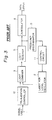
- Fig. 1 is a block diagram of the polarization diversity light receiving system using the conventional intermediate frequency combining.
- Reference numeral 1 indicates signal light having propagated over an optical fiber transmission line; 2 a laser for local oscillation; 3 a light combiner for combining the signal light with local oscillator light; 4 a polarized light separating element for separating combined signal light and local oscillator light into two orthogonally polarized components; 5 a and 5 b light receivers, each converting to an electrical signal a beat component of the light into which the signal light and local oscillation light have been orthogonally combined; 6 a and 6 b weighting circuits for weighting the respective received signals, as required, for an optimum combination thereof; 7 an automatic phase adjustment adder for adding together the two weighted received signals while adjusting their phases relative to each other; and 8 a demodulator for demodulating the modulated received signal.
- the second system is one that combines the two received signals after demodulating them independently of each other (which system will hereinafter be referred to as "baseband combining").
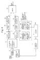
- Fig. 2 is a block diagram of the polarization diversity light receiving system employing the conventional baseband combining. In Fig. 2 parts having the same functions as those in Fig. 1 are identified by the same reference numerals and no description will be repeated in connection with them.
- the feature of the polarization diversity light receiving system utilizing the baseband combining resides in that the received signals split into orthogonally polarized waves and then converted into electrical signals are demodulated by demodulators 8 a and 8 b , respectively, and the demodulated signals are added together by an adder 9 after being weighted.
- the baseband combining differs from the intermediate frequency combining in an arrangement in which the electrical signals converted by the light receivers 5 a and 5 b are demodulated by the demodulators 8 a and 8 b and then weighted, respectively, thereafter being added together.
- Fig. 3 is a schematic diagram of a coherent type light receiving system employing the conventional intermediate frequency stabilizing.
- Reference numeral 12 indicates a polarization controller by which the planes of polarization of the signal light 1 and the local oscillator light emitted from the local oscillator laser 2 are brought into agreement with each other, 10 a frequency discriminator for generating an output voltage corresponding to a frequency fluctuation, and 11 a control circuit for controlling the oscillation wavelength (i.e. frequency) of the local oscillator laser 2 in accordance with the output voltage of the frequency discriminator 10.
- a polarization controller by which the planes of polarization of the signal light 1 and the local oscillator light emitted from the local oscillator laser 2 are brought into agreement with each other
- 10 a frequency discriminator for generating an output voltage corresponding to a frequency fluctuation
- 11 a control circuit for controlling the oscillation wavelength (i.e. frequency) of the local oscillator laser 2 in accordance with the output voltage of the frequency discriminator 10.
- the received signal converted into an electrical signal is fedback to the laser via the frequency discriminator 10 so as to make the frequency of the local oscillator light follow the frequency of the signal light 1 having undergone a frequency fluctuation.
- the frequency discriminator 10 generates an output voltage which is provided corresponding to a frequency fluctuation.
- the frequency of the local oscillator laser is controlled by the control circuit 11 through utilization of fluctuations in the output voltage thus obtained, thereby obtaining local oscillator light of a frequency following that of the signal light.
- the local oscillator laser is controlled by use of the output from one of the light receivers 5 a and 5 b in Fig. 2, so that the output of the frequency of the frequency discriminator 10 varies by fluctuations in the state of polarization of the signal light, leading to a failure in obtaining high light receiving sensitivity.
- an intermediate frequency stabilizing system useful for the polarization diversity light receiving system employing the baseband combining which does not involve the automatic phase adjustment adder 7, but no proposals have been made up to now.
- Fig. 4 is a block diagram of an embodiment of the polarization diversity light receiving system employing the baseband combining according to the present invention.
- Reference numerals 10 a and 10 b indicate frequency discriminators for discriminating the frequencies of intermediate-frequency signals output from the light receivers 5 a and 5 b , 6 c and 6 d weighting circuits for weighting the frequency-discriminated signals as required, 9 b an adder for adding together the outputs of the weighting circuits 6 c and 6 d , 11 a control circuit for generating a frequency stabilizing signal, and 20 an intermediate frequency stabilizing circuit made up of the frequency discriminators 10 a and 10 b and the weighting circuits 6 c and 6 d .
- the intensity of a detected signal obtained by optical heterodyne or homodyne detection is in proportion to ⁇ P S P L , where P S is the power of signal light and P L is the power of local oscillator light.
- the branching ratio of the signal light by the polarized light separating element 4 be represented by ⁇ /(1 - ⁇ ) where (0 ⁇ a ⁇ 1)
- the outputs of the light receivers are in proportion to ⁇ ⁇ P S P L and ⁇ (1 - ⁇ )P S P L , respectively.
- the value ⁇ varies in the range of from 0 to 1 every moment in response to variations in the state of polarization of the signal light. Since the outputs of the frequency discriminators 10 a and 10 b are usually dependent on the intput voltage, it is impossible to stabilize the intermediate frequency regardless of the state of polarization by use of the output voltage from one of the light receivers.
- the present invention is based on the fact that the sum of squared values of the proportional coefficients ⁇ ⁇ P S P L and ⁇ (1 - ⁇ )P S P L of the output voltages from the light receivers 5 a and 5 b is not dependent on variations in the state of polarization. That is, the intermediate frequency stabilization circuit 20 is formed by connecting proper weighting circuits 6 c and 6 d to the outputs of the frequency discriminators 10 a and 10 b and is so arranged as to provide outputs each corresponding to the square of the output voltage of one of the light receivers 5 a and 5 b , and these outputs are added together by the adder 9 b to obtain the sum of the squared values.
- the received signal which is the sum of the squared values, is dependent on the frequency of the signal light but is not dependent on the state of its polarization, and this signal is applied to the control circuit 11, the output of which is applied as a control signal to the local oscillator laser 2 to control its frequency.
- the output voltage of the light receivers 5 a and 5 b can be obtained as squared values equivalently, even if the weighting circuits 6 c and 6 d are omitted.
- the present invention permits stabilization of the intermediate frequency regardless of the state of polarization of the signal light 1, making it possible to receive the signal light with a high degree of sensitivity.
- Fig. 5 illustrates another embodiment of the present invention. This embodiment is effective only for an FSK modulation system in which the signal light 1 is subjected to frequency shift keying.
- the demodulators 8 a and 8 b for demodulating FSK-modulated signals are similar in operation to the afore-mentioned frequency discriminators.
- the demodulators 8 a and 8 b for demodulating FSK-modulated signals are similar in operation to the afore-mentioned frequency discriminators.
- the outputs of the demodulators 8 a and 8 b are given, by the weighting circuits 6 a and 6 b , weights equivalently corresponding to their squares before being added together by the adder 9 a ; so that it is possible to obtain a control signal for the local oscillator laser 2 independently of the state of polarization of the signal light by partly branching the weighted outputs and adding them together by means of the adder 9 b .
- the intermediate frequency stabilization circuit 20 is equivalently constituted by the demodulators 8 a and 8 b and the weighting circuits 6 a and 6 b .
- the constitution of the present invention provides a stability of ⁇ 2 MHz regardless of the state of polarization of the signal light.
- the present invention stabilizes the intermediate frequency independently of the polarization characteristic of the signal light, and hence allows a substantial improvement of the sensitivity for receiving signal light.
- the stabilization of the intermediate frequency in the polarization diversity light receiving system can be performed independently of the state of polarization of signal light by an arrangement in which the control signal for the local oscillator laser 2 is provided equivalently in the form of the sum of squared values of the received signal.
- This improves the stability of the system and the sensitivity for receiving the signal light and permits frequency multiplexing. Accordingly, the present invention is of great practical utility.
Description
- The present invention relates to a polarization diversity light receiving system and, more particularly, to a polarization diversity light receiving system utilizing baseband combining which stabilizes intermediate frequencies.
- In heterodyne/coherent fiber optic communication it is necessary that the planes of polarization of signal light and local oscillator light be brought into agreement with each other on a photodetector of the receiver. However, the sensitivity for receiving light varies with time because the state of polarization of the signal light undergoes variations owing to various disturbances in the optical fiber transmission line. To avoid this, the polarization diversity light receiving system is employed as one of means for implementing stable light receiving sensitivity independent of variations in the state of polarization of the signal light.
- With this system, the signal light having experienced variations in its state of polarization is split into two orthogonally polarized waves at the receiving end and the two polarized waves are each detected by local oscillator light having adjusted its plane of polarization to that of the polarized wave. By electrically combining together the two received signals it is possible to suppress the influence of variations in the state of polarization.
- The polarization diversity light receiving system is divided into two types in terms of the abovementioned electrical combining method. The first is a system which electrically combines two received signals together under an intermediate-frequency condition (which system will hereinafter be referred to as "intermediate frequency combining").
- The second system is one that combines the two received signals after demodulating them independently of each other (which system will hereinafter be referred to as "baseband combining").
- With the intermediate frequency combining, since a phase difference between the two orthogonally polarized wave components caused by variations in the state of polarization of the signal light varies every moment, the automatic phase adjustment adder is needed for adjusting the phases of the two received signals at all times; so that this inevitably involves a complex arrangement. In contrast thereto, the baseband combining combines the received signals after demodulating them, and hence has the advantage of dispensing with the above-mentioned phase adjustment; and some practical embodiments have been proposed so far. On the other hand, the semiconductor laser for emitting the signal light or local oscillator light is defective in that the oscillation wavelength is liable to vary under the influences of external temperature changes and aging. When the oscillation wavelength (i.e. frequency) of the signal light or local oscillation light varies, no stable detection can be achieved. To solve this problem, it has already been proposed, as an intermediate frequency stabilizing method in the coherent type light receiving system, to feed back to the local oscillation laser an electrical signal obtained by discriminating the intermediate frequency (T. Okoshi, "Feasibility Study of Frequency-Division Multiplexing Optical Communication Systems Using Optical Heterodyne or Homodyne Schemes", Institute of Electronics and Communication Engineers of Japan, Paper of Technical Group, OQE78-139, 1979).
- However, since the conventional polarization diversity light receiving system using intermediate frequency combining has an automatic phase adjustment adder, frequency stability is affected by fluctuations in the state of polarization of the signal light. Accordingly, there is a strong demand for an intermediate frequency stabilizing system useful for the polarization diversity light receiving system employing the baseband combining which does not involve the automatic phase adjustment adder, but no proposals have been made up to now.
- An object of the present invention, is to provide a polarization diversity light receiving system employing the baseband combining which provides for increased sensitivity to received light regardless of the polarization characteristic of signal light.
- A feature of the present invention resides in that the polarization diversity light receiving system using baseband combining is arranged so that the control signal for the local oscillator laser is the sum of squared values of received signals.
- Embodiments of the present invention will now be described by way of example in comparison with prior art with reference to accompanying drawings, in which:
- Fig. 1 is a block diagram showing an example of the arrangement of a known polarization diversity light receiving system which combines two received signals by the intermediate frequency combining;
- Fig. 2 is a block diagram showing an example of the arrangement of a known polarization diversity light receiving system which combines two received signals by the baseband combining;
- Fig. 3 is a block diagram showing the outline of a known coherent type light receiving system;
- Fig. 4 is a block diagram illustrating, an embodiment of a polarization diversity light receiving system of the present invention which employs the baseband combining; and
- Fig. 5 is a block diagram illustrating, another embodiment of a polarization diversity light receiving system of the present invention employing the baseband combining and applied to FSK modulation.
- To make differences between prior art and the present invention clear, examples of the prior art will first be described.
- Fig. 1 is a block diagram of the polarization diversity light receiving system using the conventional intermediate frequency combining.
Reference numeral 1 indicates signal light having propagated over an optical fiber transmission line; 2 a laser for local oscillation; 3 a light combiner for combining the signal light with local oscillator light; 4 a polarized light separating element for separating combined signal light and local oscillator light into two orthogonally polarized components; 5a and 5b light receivers, each converting to an electrical signal a beat component of the light into which the signal light and local oscillation light have been orthogonally combined; 6a and 6b weighting circuits for weighting the respective received signals, as required, for an optimum combination thereof; 7 an automatic phase adjustment adder for adding together the two weighted received signals while adjusting their phases relative to each other; and 8 a demodulator for demodulating the modulated received signal. - The second system is one that combines the two received signals after demodulating them independently of each other (which system will hereinafter be referred to as "baseband combining"). Fig. 2 is a block diagram of the polarization diversity light receiving system employing the conventional baseband combining. In Fig. 2 parts having the same functions as those in Fig. 1 are identified by the same reference numerals and no description will be repeated in connection with them. The feature of the polarization diversity light receiving system utilizing the baseband combining resides in that the received signals split into orthogonally polarized waves and then converted into electrical signals are demodulated by
demodulators adder 9 after being weighted. - Accordingly, the baseband combining differs from the intermediate frequency combining in an arrangement in which the electrical signals converted by the
light receivers demodulators - Fig. 3 is a schematic diagram of a coherent type light receiving system employing the conventional intermediate frequency stabilizing.
Reference numeral 12 indicates a polarization controller by which the planes of polarization of thesignal light 1 and the local oscillator light emitted from thelocal oscillator laser 2 are brought into agreement with each other, 10 a frequency discriminator for generating an output voltage corresponding to a frequency fluctuation, and 11 a control circuit for controlling the oscillation wavelength (i.e. frequency) of thelocal oscillator laser 2 in accordance with the output voltage of thefrequency discriminator 10. In Fig. 3 the received signal converted into an electrical signal is fedback to the laser via thefrequency discriminator 10 so as to make the frequency of the local oscillator light follow the frequency of thesignal light 1 having undergone a frequency fluctuation. Incidentally, thefrequency discriminator 10 generates an output voltage which is provided corresponding to a frequency fluctuation. The frequency of the local oscillator laser is controlled by the control circuit 11 through utilization of fluctuations in the output voltage thus obtained, thereby obtaining local oscillator light of a frequency following that of the signal light. - However, even if the intermediate frequency stabilizing for the conventional receiving system, shown in Fig. 3, is applied to the polarization diversity light receiving system, the local oscillator laser is controlled by use of the output from one of the
light receivers frequency discriminator 10 varies by fluctuations in the state of polarization of the signal light, leading to a failure in obtaining high light receiving sensitivity. In particular, there is a strong demand for an intermediate frequency stabilizing system useful for the polarization diversity light receiving system employing the baseband combining which does not involve the automaticphase adjustment adder 7, but no proposals have been made up to now. - With reference to the accompanying drawings the present invention will hereinafter be described in detail.
- In the following description the parts corresponding to those used in the prior art examples will be indicated by the same reference numerals and will not be described in detail for the sake of brevity.
- Fig. 4 is a block diagram of an embodiment of the polarization diversity light receiving system employing the baseband combining according to the present invention.
Reference numerals 10a and 10b indicate frequency discriminators for discriminating the frequencies of intermediate-frequency signals output from thelight receivers weighting circuits frequency discriminators 10a and 10b and theweighting circuits - In general, the intensity of a detected signal obtained by optical heterodyne or homodyne detection is in proportion to √
PSPL , where PS is the power of signal light and PL is the power of local oscillator light. Accordingly, letting the branching ratio of the signal light by the polarizedlight separating element 4 be represented by α/(1 - α) where (0 ≦ a ≦ 1), the outputs of the light receivers are in proportion to √αPSPL and √(1 -α)PSPL , respectively. The value α varies in the range of from 0 to 1 every moment in response to variations in the state of polarization of the signal light. Since the outputs of thefrequency discriminators 10a and 10b are usually dependent on the intput voltage, it is impossible to stabilize the intermediate frequency regardless of the state of polarization by use of the output voltage from one of the light receivers. - In view of the above, the present invention is based on the fact that the sum of squared values of the proportional coefficients √
αPSPL and √(1 - α)PSPL of the output voltages from thelight receivers frequency stabilization circuit 20 is formed by connectingproper weighting circuits frequency discriminators 10a and 10b and is so arranged as to provide outputs each corresponding to the square of the output voltage of one of thelight receivers adder 9b to obtain the sum of the squared values. Accordingly, the received signal, which is the sum of the squared values, is dependent on the frequency of the signal light but is not dependent on the state of its polarization, and this signal is applied to the control circuit 11, the output of which is applied as a control signal to thelocal oscillator laser 2 to control its frequency. In case of employing a square-law detector as the intermediatefrequency stabilization circuit 20, the output voltage of thelight receivers weighting circuits - As described above, the present invention permits stabilization of the intermediate frequency regardless of the state of polarization of the
signal light 1, making it possible to receive the signal light with a high degree of sensitivity. - Fig. 5 illustrates another embodiment of the present invention. This embodiment is effective only for an FSK modulation system in which the
signal light 1 is subjected to frequency shift keying. Thedemodulators demodulators weighting circuits adder 9a; so that it is possible to obtain a control signal for thelocal oscillator laser 2 independently of the state of polarization of the signal light by partly branching the weighted outputs and adding them together by means of theadder 9b. In other words, the intermediatefrequency stabilization circuit 20 is equivalently constituted by thedemodulators weighting circuits - Incidentally, it was found experimentally that the constitution of the present invention provides a stability of ± 2 MHz regardless of the state of polarization of the signal light.
- As described above, the present invention stabilizes the intermediate frequency independently of the polarization characteristic of the signal light, and hence allows a substantial improvement of the sensitivity for receiving signal light.
- As described above, according to the present invention, the stabilization of the intermediate frequency in the polarization diversity light receiving system can be performed independently of the state of polarization of signal light by an arrangement in which the control signal for the
local oscillator laser 2 is provided equivalently in the form of the sum of squared values of the received signal. This improves the stability of the system and the sensitivity for receiving the signal light and permits frequency multiplexing. Accordingly, the present invention is of great practical utility.
Claims (3)
- A polarization diversity light receiving system using baseband combining in which signal light of an arbitrary plane of polarization as a result of its propagation over an optical fiber is split (4) into orthogonal polarized wave components and detected by use of oscillation light output from a local oscillator laser (2) provided at the receiving side, the polarized wave components are detected to obtain electrical signals which are combined, characterised by:
intermediate frequency stabilizing means (20) which discriminates the frequency of each of the electrical signals, generates an output voltage corresponding to a variation in the frequency, and weights the output voltage to have a squared value of the electrical signal; and
adding means (9b) for combining the outputs of the intermediate frequency stabilizing means;
wherein a control signal, which is the sum of the squared values of the electrical signals, obtained by the adding means, is used to control the local oscillator laser (2), thereby stabilizing its frequency. - A polarization diversity light receiving system using baseband combining according to claim 1 in which said intermediate frequency stabilizing means (20) is provided to receive the electrical signals in addition to demodulators (8a, 8b) of the electrical signals.
- A polarization diversity light receiving system using baseband combining according to claim 1 or 2, in which said intermediate frequency stabilizing means (20) is provided for the signal light of FSK modulation by the common use of demodulators (8a,8b) of the electrical signals and weighting circuits (6a,6b) at the outputs of the demodulators (8a,8b).
Applications Claiming Priority (2)
| Application Number | Priority Date | Filing Date | Title |
|---|---|---|---|
| JP270367/87 | 1987-10-28 | ||
| JP62270367A JP2562623B2 (en) | 1987-10-28 | 1987-10-28 | Polarization diversity optical reception method by baseband combining method |
Publications (3)
| Publication Number | Publication Date |
|---|---|
| EP0314491A2 EP0314491A2 (en) | 1989-05-03 |
| EP0314491A3 EP0314491A3 (en) | 1990-05-16 |
| EP0314491B1 true EP0314491B1 (en) | 1993-08-25 |
Family
ID=17485277
Family Applications (1)
| Application Number | Title | Priority Date | Filing Date |
|---|---|---|---|
| EP88310146A Expired - Lifetime EP0314491B1 (en) | 1987-10-28 | 1988-10-28 | Polarization diversity light receiving system |
Country Status (4)
| Country | Link |
|---|---|
| US (1) | US4888817A (en) |
| EP (1) | EP0314491B1 (en) |
| JP (1) | JP2562623B2 (en) |
| DE (1) | DE3883480T2 (en) |
Families Citing this family (15)
| Publication number | Priority date | Publication date | Assignee | Title |
|---|---|---|---|---|
| JPH063512B2 (en) * | 1988-02-19 | 1994-01-12 | 富士通株式会社 | Polarization diversity optical receiver for coherent optical communication |
| JPH0239131A (en) * | 1988-07-29 | 1990-02-08 | Hitachi Ltd | Method for stabilizing frequency interval and optical heterodyne or optical homodyne communication method |
| JPH02162330A (en) * | 1988-12-16 | 1990-06-21 | Hitachi Ltd | Method and device for receiving polarization diversity light and method for stabilizing intermediate frequency |
| JP2540935B2 (en) * | 1989-03-16 | 1996-10-09 | 日本電気株式会社 | Collective polarization control method |
| US5115332A (en) * | 1989-07-20 | 1992-05-19 | Fujitsu Limited | Receiver for coherent optical communication |
| JPH04150628A (en) * | 1990-10-15 | 1992-05-25 | Nec Corp | Wavelength stabilizing method for optical communication system and its circuit |
| US5321850A (en) * | 1991-10-09 | 1994-06-14 | Telefonaktiebolaget L M Ericsson | Diversity radio receiver automatic frequency control |
| US5388088A (en) * | 1992-04-02 | 1995-02-07 | At&T Corp. | Multiple polarization sensitive detection arrangement for fiber optic communications |
| JP2689875B2 (en) * | 1993-12-24 | 1997-12-10 | 日本電気株式会社 | Optical signal receiver |
| JPH08509350A (en) * | 1994-02-18 | 1996-10-01 | フィリップス、エレクトロニクス、ネムローゼ、フェンノートシャップ | Wideband multiplicative characteristic detector having triangular frequency characteristic, and transmission system and receiver including the detector |
| DE19612604A1 (en) * | 1996-03-29 | 1997-10-02 | Sel Alcatel Ag | Optical receiver with an equalizer circuit for interference caused by PMD and system with such an optical receiver |
| AU2006320392B2 (en) | 2005-11-30 | 2013-01-17 | AbbVie Deutschland GmbH & Co. KG | Monoclonal antibodies against amyloid beta protein and uses thereof |
| US7406269B2 (en) * | 2006-03-10 | 2008-07-29 | Discovery Semiconductors, Inc. | Feedback-controlled coherent optical receiver with electrical compensation/equalization |
| US9337937B2 (en) * | 2014-03-10 | 2016-05-10 | Cisco Technology, Inc. | Common mode rejection ratio control for coherent optical receivers |
| JP6884948B2 (en) * | 2017-03-17 | 2021-06-09 | 国立研究開発法人情報通信研究機構 | High speed photo detector array |
Family Cites Families (6)
| Publication number | Priority date | Publication date | Assignee | Title |
|---|---|---|---|---|
| JPS59122140A (en) * | 1982-12-28 | 1984-07-14 | Nec Corp | Optical heterodyne detector |
| JPH0618348B2 (en) * | 1984-02-06 | 1994-03-09 | 日本電信電話株式会社 | Optical receiver circuit controller |
| GB8515499D0 (en) * | 1985-06-19 | 1985-07-24 | British Telecomm | Digital information transmission system |
| US4723315A (en) * | 1986-06-24 | 1988-02-02 | Itek Corporation | Polarization matching mixer |
| DE3621734A1 (en) * | 1986-06-28 | 1988-01-07 | Standard Elektrik Lorenz Ag | OPTICAL OVERLAY RECEIVER |
| US4718120A (en) * | 1986-11-24 | 1988-01-05 | American Telephone And Telegraph Company, At&T Bell Laboratories | Polarization insensitive coherent lightwave detector |
-
1987
- 1987-10-28 JP JP62270367A patent/JP2562623B2/en not_active Expired - Lifetime
-
1988
- 1988-10-17 US US07/258,817 patent/US4888817A/en not_active Expired - Lifetime
- 1988-10-28 EP EP88310146A patent/EP0314491B1/en not_active Expired - Lifetime
- 1988-10-28 DE DE88310146T patent/DE3883480T2/en not_active Expired - Fee Related
Also Published As
| Publication number | Publication date |
|---|---|
| EP0314491A2 (en) | 1989-05-03 |
| DE3883480T2 (en) | 1993-12-23 |
| JP2562623B2 (en) | 1996-12-11 |
| JPH01114832A (en) | 1989-05-08 |
| DE3883480D1 (en) | 1993-09-30 |
| EP0314491A3 (en) | 1990-05-16 |
| US4888817A (en) | 1989-12-19 |
Similar Documents
| Publication | Publication Date | Title |
|---|---|---|
| EP0314491B1 (en) | Polarization diversity light receiving system | |
| EP0251062B1 (en) | Dual balanced optical signal receiver | |
| US5687261A (en) | Fiber-optic delay-line stabilization of heterodyne optical signal generator and method using same | |
| EP0352809B1 (en) | Polarization diversity optical heterodyne receiver with phase adjustment of two i.f. signals for control of a local optical source | |
| US20090016723A1 (en) | Optical-wireless hybrid transmission system and optical-wireless hybrid transmission method | |
| US5146359A (en) | Double-stage phase-diversity receiver | |
| US5367397A (en) | Wavelength-stabilizing method and its associated circuitry for an optical communication system | |
| US5140453A (en) | Optical receiving method utilizing polarization diversity and apparatus for carrying out the same | |
| JP2658180B2 (en) | Polarization diversity optical receiver | |
| US5510927A (en) | Method for setting the local oscillator of an optical superheterodyne receiver | |
| JPH0572777B2 (en) | ||
| US6043921A (en) | Fading-free optical phase rate receiver | |
| EP0390069B1 (en) | Polarization diversity heterodyne receiver of a baseband combining type in which i.f. signals are adjusted by negative feedback from a device output signal | |
| US5568305A (en) | Heterodyne receiver provided with a frequency discriminator for coherent lightwave communications | |
| JPH05191352A (en) | Coherent optical fiber communication system using polarized-light modulation | |
| JPH04248721A (en) | Balanced optical receiver | |
| US5414550A (en) | Optical heterodyne detector and receiver | |
| Knibbe et al. | Integrated heterodyne receiver and spatial tracker for binary FSK communication | |
| Takamasa et al. | Polarization diversity technique for coherent optical detection | |
| JPH02120726A (en) | Coherent light communication system | |
| JP2734137B2 (en) | Dual polarization receiving system | |
| JPH0795178B2 (en) | Intermediate frequency stabilization method | |
| US5629959A (en) | Wideband square-law detector having a triangular frequency characteristic as well as a transmission system and a receiver including such a detector | |
| Watanabe et al. | Polarisation-insensitive 1.2 Gb/s optical DPSK heterodyne transmission experiment using polarisation diversity | |
| JPH03259632A (en) | Optical heterodyne polarized wave diversity receiver |
Legal Events
| Date | Code | Title | Description |
|---|---|---|---|
| PUAI | Public reference made under article 153(3) epc to a published international application that has entered the european phase |
Free format text: ORIGINAL CODE: 0009012 |
|
| AK | Designated contracting states |
Kind code of ref document: A2 Designated state(s): DE FR GB |
|
| PUAL | Search report despatched |
Free format text: ORIGINAL CODE: 0009013 |
|
| AK | Designated contracting states |
Kind code of ref document: A3 Designated state(s): DE FR GB |
|
| 17P | Request for examination filed |
Effective date: 19900719 |
|
| 17Q | First examination report despatched |
Effective date: 19921028 |
|
| GRAA | (expected) grant |
Free format text: ORIGINAL CODE: 0009210 |
|
| AK | Designated contracting states |
Kind code of ref document: B1 Designated state(s): DE FR GB |
|
| REF | Corresponds to: |
Ref document number: 3883480 Country of ref document: DE Date of ref document: 19930930 |
|
| ET | Fr: translation filed | ||
| PLBE | No opposition filed within time limit |
Free format text: ORIGINAL CODE: 0009261 |
|
| STAA | Information on the status of an ep patent application or granted ep patent |
Free format text: STATUS: NO OPPOSITION FILED WITHIN TIME LIMIT |
|
| 26N | No opposition filed | ||
| PGFP | Annual fee paid to national office [announced via postgrant information from national office to epo] |
Ref country code: GB Payment date: 20010914 Year of fee payment: 14 |
|
| PGFP | Annual fee paid to national office [announced via postgrant information from national office to epo] |
Ref country code: DE Payment date: 20011005 Year of fee payment: 14 |
|
| PGFP | Annual fee paid to national office [announced via postgrant information from national office to epo] |
Ref country code: FR Payment date: 20011011 Year of fee payment: 14 |
|
| REG | Reference to a national code |
Ref country code: GB Ref legal event code: IF02 |
|
| PG25 | Lapsed in a contracting state [announced via postgrant information from national office to epo] |
Ref country code: GB Free format text: LAPSE BECAUSE OF NON-PAYMENT OF DUE FEES Effective date: 20021028 |
|
| PG25 | Lapsed in a contracting state [announced via postgrant information from national office to epo] |
Ref country code: DE Free format text: LAPSE BECAUSE OF NON-PAYMENT OF DUE FEES Effective date: 20030501 |
|
| GBPC | Gb: european patent ceased through non-payment of renewal fee | ||
| PG25 | Lapsed in a contracting state [announced via postgrant information from national office to epo] |
Ref country code: FR Free format text: LAPSE BECAUSE OF NON-PAYMENT OF DUE FEES Effective date: 20030630 |
|
| REG | Reference to a national code |
Ref country code: FR Ref legal event code: ST |