EP0314404B2 - Öfen - Google Patents
Öfen Download PDFInfo
- Publication number
- EP0314404B2 EP0314404B2 EP19880309936 EP88309936A EP0314404B2 EP 0314404 B2 EP0314404 B2 EP 0314404B2 EP 19880309936 EP19880309936 EP 19880309936 EP 88309936 A EP88309936 A EP 88309936A EP 0314404 B2 EP0314404 B2 EP 0314404B2
- Authority
- EP
- European Patent Office
- Prior art keywords
- closed well
- furnace
- chamber
- main heating
- closed
- Prior art date
- Legal status (The legal status is an assumption and is not a legal conclusion. Google has not performed a legal analysis and makes no representation as to the accuracy of the status listed.)
- Expired - Lifetime
Links
Images


Classifications
-
- C—CHEMISTRY; METALLURGY
- C22—METALLURGY; FERROUS OR NON-FERROUS ALLOYS; TREATMENT OF ALLOYS OR NON-FERROUS METALS
- C22B—PRODUCTION AND REFINING OF METALS; PRETREATMENT OF RAW MATERIALS
- C22B7/00—Working up raw materials other than ores, e.g. scrap, to produce non-ferrous metals and compounds thereof; Methods of a general interest or applied to the winning of more than two metals
- C22B7/001—Dry processes
- C22B7/003—Dry processes only remelting, e.g. of chips, borings, turnings; apparatus used therefor
-
- C—CHEMISTRY; METALLURGY
- C22—METALLURGY; FERROUS OR NON-FERROUS ALLOYS; TREATMENT OF ALLOYS OR NON-FERROUS METALS
- C22B—PRODUCTION AND REFINING OF METALS; PRETREATMENT OF RAW MATERIALS
- C22B21/00—Obtaining aluminium
- C22B21/0084—Obtaining aluminium melting and handling molten aluminium
- C22B21/0092—Remelting scrap, skimmings or any secondary source aluminium
-
- F—MECHANICAL ENGINEERING; LIGHTING; HEATING; WEAPONS; BLASTING
- F27—FURNACES; KILNS; OVENS; RETORTS
- F27B—FURNACES, KILNS, OVENS OR RETORTS IN GENERAL; OPEN SINTERING OR LIKE APPARATUS
- F27B3/00—Hearth-type furnaces, e.g. of reverberatory type; Electric arc furnaces ; Tank furnaces
- F27B3/04—Hearth-type furnaces, e.g. of reverberatory type; Electric arc furnaces ; Tank furnaces of multiple-hearth type; of multiple-chamber type; Combinations of hearth-type furnaces
- F27B3/045—Multiple chambers, e.g. one of which is used for charging
-
- F—MECHANICAL ENGINEERING; LIGHTING; HEATING; WEAPONS; BLASTING
- F27—FURNACES; KILNS; OVENS; RETORTS
- F27D—DETAILS OR ACCESSORIES OF FURNACES, KILNS, OVENS OR RETORTS, IN SO FAR AS THEY ARE OF KINDS OCCURRING IN MORE THAN ONE KIND OF FURNACE
- F27D19/00—Arrangements of controlling devices
-
- F—MECHANICAL ENGINEERING; LIGHTING; HEATING; WEAPONS; BLASTING
- F27—FURNACES; KILNS; OVENS; RETORTS
- F27B—FURNACES, KILNS, OVENS OR RETORTS IN GENERAL; OPEN SINTERING OR LIKE APPARATUS
- F27B3/00—Hearth-type furnaces, e.g. of reverberatory type; Electric arc furnaces ; Tank furnaces
- F27B3/06—Hearth-type furnaces, e.g. of reverberatory type; Electric arc furnaces ; Tank furnaces with movable working chambers or hearths, e.g. tiltable, oscillating or describing a composed movement
- F27B3/065—Hearth-type furnaces, e.g. of reverberatory type; Electric arc furnaces ; Tank furnaces with movable working chambers or hearths, e.g. tiltable, oscillating or describing a composed movement tiltable
-
- F—MECHANICAL ENGINEERING; LIGHTING; HEATING; WEAPONS; BLASTING
- F27—FURNACES; KILNS; OVENS; RETORTS
- F27D—DETAILS OR ACCESSORIES OF FURNACES, KILNS, OVENS OR RETORTS, IN SO FAR AS THEY ARE OF KINDS OCCURRING IN MORE THAN ONE KIND OF FURNACE
- F27D3/00—Charging; Discharging; Manipulation of charge
- F27D2003/0034—Means for moving, conveying, transporting the charge in the furnace or in the charging facilities
- F27D2003/0054—Means to move molten metal, e.g. electromagnetic pump
-
- F—MECHANICAL ENGINEERING; LIGHTING; HEATING; WEAPONS; BLASTING
- F27—FURNACES; KILNS; OVENS; RETORTS
- F27M—INDEXING SCHEME RELATING TO ASPECTS OF THE CHARGES OR FURNACES, KILNS, OVENS OR RETORTS
- F27M2001/00—Composition, conformation or state of the charge
- F27M2001/01—Charges containing mainly non-ferrous metals
- F27M2001/012—Aluminium
-
- F—MECHANICAL ENGINEERING; LIGHTING; HEATING; WEAPONS; BLASTING
- F27—FURNACES; KILNS; OVENS; RETORTS
- F27M—INDEXING SCHEME RELATING TO ASPECTS OF THE CHARGES OR FURNACES, KILNS, OVENS OR RETORTS
- F27M2001/00—Composition, conformation or state of the charge
- F27M2001/15—Composition, conformation or state of the charge characterised by the form of the articles
-
- Y—GENERAL TAGGING OF NEW TECHNOLOGICAL DEVELOPMENTS; GENERAL TAGGING OF CROSS-SECTIONAL TECHNOLOGIES SPANNING OVER SEVERAL SECTIONS OF THE IPC; TECHNICAL SUBJECTS COVERED BY FORMER USPC CROSS-REFERENCE ART COLLECTIONS [XRACs] AND DIGESTS
- Y02—TECHNOLOGIES OR APPLICATIONS FOR MITIGATION OR ADAPTATION AGAINST CLIMATE CHANGE
- Y02P—CLIMATE CHANGE MITIGATION TECHNOLOGIES IN THE PRODUCTION OR PROCESSING OF GOODS
- Y02P10/00—Technologies related to metal processing
- Y02P10/20—Recycling
Definitions
- the present invention relates to furnaces and more particularly to furnaces for melting scrap metal and in particular aluminium.
- a first known furnace for melting scrap material is the open well furnace in which metal to be melted is placed into an open bath of molten metal which is kept at a high temperature by an inner furnace, gates being provided to control the flow of metal to and from the inner furnace to control the heating of the scrap metal.
- Such a furnace has the disadvantage that large amounts of heat are lost by the open bath and although a fume hood is normally provided there is often an escape of polluted flue gases on loading of the furnace.
- Closed Well Furnaces comprise two closed compartments separated by a wall which extends vertically downwards.
- the molten metal usually aluminium
- the molten metal is contained within a well and the surface level of the aluminium is above the bottom of the wall thereby dividing the furnace into two separate closed compartments.
- One compartment comprises a heating compartment in which burners heat the molten metal and the other compartment comprises a melting compartment into which scrap metal and other material to be melted is fed.
- the scrap metal (usually aluminium) is heated by the bath of molten metal in the well without being subjected to direct heat from burners. This is important in the smelting of aluminium since aluminium is susceptible to oxidation especially if thin scrap is to be melted.
- US Patent No. 2264740 shows a fumace comprising a main heating chamber, a further chamber for melting scrap and a gas duct connecting the chambers.
- the furnace also comprises feeding and heating chambers, the bottom of the former being inclined downwardly towards the heating chamber. This inclination however stops adjacent the separating refractory wall just inside the heating chamber.
- DE-A-3 444 181 describes a closed well furnace for melting aluminium scrap the furnace comprising a main heating chamber and a closed well melting chamber, a refractory dividing wall separating the main heating chamber and the closed well melting chamber.
- the dividing wall of this furnace descends to the floor of the well except for an opening at the bottom of the dividing wall which opening extends over part of the width of the dividing wall.
- the CWF furnace comprises a main heating chamber 10 and a closed well melting chamber 20 separated by a dividing wall 30 of refractory material and preferably water or air cooled (not shown).
- the main heating chamber has exhaust outlets 12 and heating burners 14 and a sliding door 16 preferably counterbalanced by a weight 18.
- a tapped outlet 19 is also provided controllable by any suitable valve means (not shown).
- the melting chamber 20 has an exhaust fume outlet 22 and a sliding door 24 preferably counterbalanced by a weight 26. Aluminium scrap to be melted is placed into chamber 20 via open door 24 and the door is then closed to effectively seal the furnace.
- the floor, walls and roof of the furnace are made from refractory material and doors 24 and 16 are also lined with refractory material. Heat loss through the walls etc is kept to a minimum.
- the longitudinal cross-sectional shape of the floor 40 of the furnace is not rectangular as in the known closed well furnace.
- the floor 40 is sloped from the melting bath chamber 20 down towards the heating door 16 end of chamber 10.
- the slope of the floor over its centre portion 42 is relatively shallow being preferably less than 5°. In a preferred embodiment the slope of the centre portion of the floor 42 is about 3°.
- the floor 44 slopes steeply upwards to guide scrap material 28 (shown dotted) down onto floor portion 42.
- the floor portion 46 slopes less steeply to allow raking of molten metal out of the chamber.
- the slope of floor portion 42 assist in providing a convection current (shown dotted) which circulates the molten metal in the path shown.
- the heated molten metal on the upper part of path 48 therefore flows more rapidly past the scrap 28 thereby melting the scrap at a greater rate than if the floor portion 42 were horizontal. This is extremely advantageous since this considerably increases the throughput of the furnace and hence its efficiency.
- the floor 40 of the well in plan view resembles a rectangle divided into three smaller rectangles 42, 44 and 46.
- the corners of the rectangles are given the reference letters A to H.
- the line F, D is shown dotted to indicate that the corner D is below corner C.
- the floor of the well therefore in this embodiment not only falls from point E to point C and from point F to point D but also falls from point C to point D.
- the burners 14 can be directed at right angles across the chamber 10 as indicated by first burner 14 or can be directed at an angle as indicated by burners 14', 14". By directing the burners at an angle the flow of molten metal can be assisted by the blast from the burners. This again increases the melt rate of the furnace.
- the establishment of such a pattern may be assisted by providing an "opening" 32 in the dividing wall 30.
- the opening may, depending on the height of the base of wall 30 relative to the upper surface of the molten metal, be above the surface, allowing gases to pass between the furnaces, or just below the surface.
- the opening 32 provides an easier passageway for the molten metal and therefore is persuasive in directing the flow of the molten metal.
- a further opening such as shown dotted at 34 may be provided to further guide the flow of molten metal on its return journey.
- Chamber 10 is connected to chamber 20 via a hot gas duct 70 and exhaust ducts 80 and 90 respectively connect chambers 10 and 20 to an exhaust flue or chimney (not shown).
- exhaust flues 80, 90 may be connected to a fume purification plant to remove unwanted material from the exhaust gases).
- hot gas damper 100 In hot gas duct 70 a hot gas damper 100 is installed. Normally, the temperature in the main heating chamber 10, by direct heat from the installed burners on that chamber, will be at a higher temperature than the closed well chamber 20. As specified hereinbefore scrap metal will normally be charged into the closed well chamber 20.
- the temperature in the closed well chamber - using an automatic control system - can be set at any desired level. The automatic control system will open the hot gas damper 100 in the hot gas duct 70 connecting the main heating chamber with the closed well chamber and it will close the flue gas damper 200 which connects the main heating chamber to the flue gas exhaust system.
- Opening and closing of both said dampers 100, 200 will be controlled in such a way, that the static pressure in the main heating chamber 10 during such occasions, will be held at a higher level than the static pressure in the closed well chamber 20. By doing so, a positive hot gas flow from the main heating chamber through the inter-connecting hot gas duct will be maintained in accordance with the differential pressure held and the inter-connecting hot gas duct.
- the hot gas damper 100 in the inter-connecting duct system between the two chambers 10, 20 will be kept closed to avoid unnecessary heat loss.
- the static pressure in the main heating chamber 10 will be immediately decreased by opening the flue gas damper 200 in the exhaust duct from that chamber fully.
- the hot gas damper 100 in the interconnecting duct 70 between both chambers will also open fully, so giving the opportunity to the closed well chamber 20 to dump any excess heat into the main heating chamber 10 without delay.
- the burners 14 installed on the main heating chamber 10 will turn down immediately in such an event.
- the above operation can be controlled by sensing the temperature in the closed well chamber 20 by means for example of a detector 400.
- the set temperature is determined by the furnace system but will be at a temperature above that at which the closed well chamber 20 normally operates.
- the damper 100 will be open and hot air will be supplied from the main heating chamber 10 to the closed well chamber 20 to heat the scrap charged into the chamber 20.
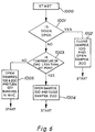
- the operation can be controlled for example by any suitable microprocessor and a simplified flow diagram is shown in Figure 6 for this operation.
- the temperature detector 400 is monitored in function 1003. If the temperature is below the set temperature then damper 100 is opened (or maintained open) and damper 200 is closed in function 1004. The programme then restarts at appropriate intervals (say every 5 milliseconds).
- function 1004 detects this and enables function 1005 which opens damper 100 and damper 200 and also turns off the burners (if ON) in MHC 20.
- control sequence may form part of a much more complex control sequence for the furnace and has been considerably simplified to more clearly explain the principle of the inventive feature.
Landscapes
- Engineering & Computer Science (AREA)
- Chemical & Material Sciences (AREA)
- Mechanical Engineering (AREA)
- Manufacturing & Machinery (AREA)
- Materials Engineering (AREA)
- Metallurgy (AREA)
- Organic Chemistry (AREA)
- General Engineering & Computer Science (AREA)
- Life Sciences & Earth Sciences (AREA)
- Environmental & Geological Engineering (AREA)
- General Life Sciences & Earth Sciences (AREA)
- Geology (AREA)
- Vertical, Hearth, Or Arc Furnaces (AREA)
- Crystals, And After-Treatments Of Crystals (AREA)
- Manufacture And Refinement Of Metals (AREA)
- Feeding, Discharge, Calcimining, Fusing, And Gas-Generation Devices (AREA)
- Catalysts (AREA)
- Glass Compositions (AREA)
- Processing And Handling Of Plastics And Other Materials For Molding In General (AREA)
- Furnace Details (AREA)
- Plural Heterocyclic Compounds (AREA)
- Crucibles And Fluidized-Bed Furnaces (AREA)
- Tunnel Furnaces (AREA)
- Gasification And Melting Of Waste (AREA)
Claims (10)
- Geschlossener Wannenofen zum Schmelzen von Aluminiumschrott, umfassend einen Hauptheizraum (10) und einen geschlossenen Wannen-Schmelzraum (20), wobei eine feuerfeste Trennwand (30) den Hauptheizraum und den geschlossenen Wannen-Schmelzraum voneinander trennt, der Boden der Wanne (42) über praktisch die gesamte Länge des geschlossenen Wannen-Schmelzraums und des Hauptheizraums fortlaufend ist, die feuerfeste Trennwand (30) eine hängende, nicht bis zum Boden der Wanne herabreichende Wand ist und der Boden der Wanne über praktisch seine gesamte Breite und Länge in einer Abwärtsrichtung vom geschlossenen Wannen-Schmelzraum (20) zum Hauptheizraum (10) abfällt, um die Umwälzung flüssiger Schmelze zwischen dem Hauptheizraum (10) und dem geschlossenen Wannen-Schmelzraum (20) des Ofens zu unterstützen.
- Geschlossener Wannenofen nach Anspruch 1, dadurch gekennzeichnet, daß das Gefälle vergleichsweise flach ist und weniger als 5° gegenüber der Waagerechten beträgt.
- Geschlossener Wannenofen nach Anspruch 1, dadurch gekennzeichnet, daß der Boden (42) der Wanne eine im wesentlichen rechteckige Form (CDEF) besitzt und der Boden zusätzlich zum Abwärtsgefälle in Richtung auf den Hauptraum auch ein diagonales Gefälle (ED) aufweist.
- Geschlossener Wannenofen nach einem der Ansprüche 1 bis 3, dadurch gekennzeichnet, daß die feuerfeste Trennwand (30) am Oberflächenspiegel der Metallschmelze mit einer Öffnung (32), um einen Strom des Metalls hindurchfließen zu lassen, versehen ist.
- Geschlossener Wannenofen nach Anspruch 4, dadurch gekennzeichnet, daß innerhalb des Hauptheizraums (10) mindestens ein Heißluftbrenner (14') angeordnet ist, der zum Richten des bei seiner Betätigung von ihm selbst erzeugten Heißluftstroms in einer Richtung unter einem spitzen Winkel zur Wand des Hauptheizraums (10) positioniert ist, so daß der Heißluftstrom die Strömung der flüssigen Schmelze innerhalb des Ofens unterstützt.
- Geschlossener Wannenofen nach Anspruch 1, dadurch gekennzeichnet, daß eine den Hauptheizraum und den geschlossenen Wannen-Schmelzraum verbindende Heißgasleitung (70) vorgesehen ist, die einen Heißgas(absperr)schieber (100) enthält, welcher die Heißgasleitung zur Verhinderung einer Heißgasströmung durch die Leitung zu schließen bzw. abzusperren vermag.
- Geschlossener Wannenofen nach Anspruch 6, dadurch gekennzeichnet, daß die Stellung des Heißgas(absperr)schiebers (100) durch ein Steuersystem in Abhängigkeit von der Temperaturdifferenz zwischen dem Hauptheizraum und dem geschlossenen Wannen-Schmelzraum gesteuert wird, wobei das Steuersystem normalerweise zum Öffnen des (Absperr-)Schiebers (100) wirksam wird, wenn die Temperatur des Hauptheizraums (10) höher ist als die des geschlossenen Wannen-Schmelzraums (20).
- Geschlossener Wannenofen nach Anspruch 6, dadurch gekennzeichnet, daß der (Absperr-)Schieber (100) geschlossen wird, wenn zu schmelzender Schrott in den geschlossenen Wannen-Schmelzraum (20) eingeführt wird.
- Geschlossener Wannenofen nach Anspruch 8, dadurch gekennzeichnet, daß auch eine den geschlossenen Wannen-Schmelzraum mit einem Auslaß- oder Abgasrauchrohr verbindende Heißgasauslaßleitung (90) vorgesehen ist, die einen Abgas(absperr)schieber (300) zum wirksamen Abdichten bzw. Verschließen der Auslaßleitung und eine Einrichtung zum Öffnen des Heißgas(absperr)schiebers (100), wenn die Temperatur im geschlossenen Wannen-Schmelzraum über einen vorbestimmten Sollwert hinaus ansteigt, aufweist.
- Geschlossener Wannenofen nach Anspruch 6, dadurch gekennzeichnet, daß während der Zeitspanne, in welcher die Temperatur im geschlossenen Wannen-Schmelzraum (20) über dem vorbestimmten Sollwert liegt, der Heißgas(absperr)schieber (100) zwischen dem geschlossenen Wannen-Schmelzraum und dem Hauptheizraum geöffnet wird, um Gas aus dem geschlossenen Wannen-Schmelzraum (20) zum Hauptheizraum (10) strömen zu lassen.
Priority Applications (1)
| Application Number | Priority Date | Filing Date | Title |
|---|---|---|---|
| AT88309936T ATE91011T1 (de) | 1987-10-24 | 1988-10-21 | Oefen. |
Applications Claiming Priority (2)
| Application Number | Priority Date | Filing Date | Title |
|---|---|---|---|
| GB8724944 | 1987-10-24 | ||
| GB8724944A GB8724944D0 (en) | 1987-10-24 | 1987-10-24 | Furnaces |
Publications (3)
| Publication Number | Publication Date |
|---|---|
| EP0314404A1 EP0314404A1 (de) | 1989-05-03 |
| EP0314404B1 EP0314404B1 (de) | 1993-06-23 |
| EP0314404B2 true EP0314404B2 (de) | 1997-08-06 |
Family
ID=10625832
Family Applications (1)
| Application Number | Title | Priority Date | Filing Date |
|---|---|---|---|
| EP19880309936 Expired - Lifetime EP0314404B2 (de) | 1987-10-24 | 1988-10-21 | Öfen |
Country Status (12)
| Country | Link |
|---|---|
| US (1) | US5035402A (de) |
| EP (1) | EP0314404B2 (de) |
| JP (1) | JPH01239383A (de) |
| CN (1) | CN1017084B (de) |
| AT (1) | ATE91011T1 (de) |
| AU (1) | AU614779B2 (de) |
| CA (1) | CA1315098C (de) |
| DE (1) | DE3882010T3 (de) |
| ES (1) | ES2045143T3 (de) |
| GB (2) | GB8724944D0 (de) |
| NO (1) | NO172514C (de) |
| ZA (1) | ZA887941B (de) |
Families Citing this family (8)
| Publication number | Priority date | Publication date | Assignee | Title |
|---|---|---|---|---|
| GB9025759D0 (en) * | 1990-11-27 | 1991-01-09 | Copermill Ltd | Apparatus for melting aluminium |
| EP0652295B1 (de) * | 1993-11-10 | 1999-03-10 | ALUMINIUM RHEINFELDEN GmbH | Verfahren und Vorrichtung zur umweltgerechten Rückgewinnung von Aluminium aus Abfällen |
| EP0666328B1 (de) * | 1994-02-07 | 1998-11-11 | ALUMINIUM RHEINFELDEN GmbH | Verfahren und Vorrichtung zur umweltgerechten Rückgewinnung von Aluminium aus Abfällen |
| US6245122B1 (en) | 2000-01-20 | 2001-06-12 | J. W. Aluminum Company | Apparatus and method for reclaiming scrap metal |
| US6648284B2 (en) * | 2001-09-05 | 2003-11-18 | Lockheed Martin Corporation | Flat tub mail positional orientation justification insert |
| JP4821549B2 (ja) * | 2006-10-02 | 2011-11-24 | 株式会社デンソー | 溶解保持装置 |
| JP5766572B2 (ja) * | 2011-09-30 | 2015-08-19 | 高橋 謙三 | 金属溶解炉用渦室体及びそれを用いた金属溶解炉 |
| DE102012103275A1 (de) * | 2012-04-16 | 2013-10-17 | Benteler Automobiltechnik Gmbh | Schichtofenanlage sowie Verfahren zum Betreiben der Schichtofenanlage |
Family Cites Families (5)
| Publication number | Priority date | Publication date | Assignee | Title |
|---|---|---|---|---|
| US2264740A (en) * | 1934-09-15 | 1941-12-02 | John W Brown | Melting and holding furnace |
| DE726802C (de) * | 1941-01-19 | 1942-10-21 | Hoeveler & Dieckhaus | Schmelzofenanlage mit Vorfeuerung und Abwaermeverwertung |
| US3163520A (en) * | 1960-12-27 | 1964-12-29 | Elektrokemisk As | Process and apparatus for preheating and pre-reduction of charge to electric furnace |
| US3933343A (en) * | 1972-08-28 | 1976-01-20 | U.S. Reduction Co. | Method and apparatus for melting metals |
| US4319921A (en) * | 1980-10-20 | 1982-03-16 | The Celotex Corporation | Heat recovery and melting system for scrap metals |
-
1987
- 1987-10-24 GB GB8724944A patent/GB8724944D0/en active Pending
-
1988
- 1988-10-20 US US07/260,399 patent/US5035402A/en not_active Expired - Fee Related
- 1988-10-21 DE DE3882010T patent/DE3882010T3/de not_active Expired - Fee Related
- 1988-10-21 EP EP19880309936 patent/EP0314404B2/de not_active Expired - Lifetime
- 1988-10-21 ES ES88309936T patent/ES2045143T3/es not_active Expired - Lifetime
- 1988-10-21 GB GB8824753A patent/GB2211590B/en not_active Expired - Lifetime
- 1988-10-21 CA CA 581005 patent/CA1315098C/en not_active Expired - Fee Related
- 1988-10-21 AT AT88309936T patent/ATE91011T1/de not_active IP Right Cessation
- 1988-10-24 NO NO884711A patent/NO172514C/no not_active IP Right Cessation
- 1988-10-24 JP JP63267987A patent/JPH01239383A/ja active Pending
- 1988-10-24 ZA ZA887941A patent/ZA887941B/xx unknown
- 1988-10-24 CN CN88107388A patent/CN1017084B/zh not_active Expired
- 1988-10-24 AU AU24190/88A patent/AU614779B2/en not_active Ceased
Also Published As
| Publication number | Publication date |
|---|---|
| GB8824753D0 (en) | 1988-11-30 |
| EP0314404A1 (de) | 1989-05-03 |
| AU614779B2 (en) | 1991-09-12 |
| NO172514C (no) | 1993-07-28 |
| CN1033099A (zh) | 1989-05-24 |
| ES2045143T3 (es) | 1994-01-16 |
| NO884711D0 (no) | 1988-10-24 |
| NO884711L (no) | 1989-04-25 |
| GB2211590A (en) | 1989-07-05 |
| JPH01239383A (ja) | 1989-09-25 |
| GB2211590B (en) | 1991-09-18 |
| CN1017084B (zh) | 1992-06-17 |
| DE3882010T3 (de) | 1998-01-22 |
| ATE91011T1 (de) | 1993-07-15 |
| US5035402A (en) | 1991-07-30 |
| CA1315098C (en) | 1993-03-30 |
| NO172514B (no) | 1993-04-19 |
| DE3882010D1 (de) | 1993-07-29 |
| GB8724944D0 (en) | 1987-11-25 |
| DE3882010T2 (de) | 1993-12-16 |
| AU2419088A (en) | 1989-04-27 |
| EP0314404B1 (de) | 1993-06-23 |
| ZA887941B (en) | 1989-07-26 |
Similar Documents
| Publication | Publication Date | Title |
|---|---|---|
| US4060408A (en) | Melting process | |
| EP0314404B2 (de) | Öfen | |
| FI72750C (fi) | Tillvaratagande av vaerme och smaeltsystem foer skrotmetall. | |
| EP0407664B1 (de) | Schmelz- und Warmhalteofen | |
| US4445849A (en) | Device for thermal treatment of scrap | |
| US3760446A (en) | Gas curtain ventilation control for open hooded ferroalloy furnace | |
| US4200265A (en) | Furnace for the melting and refining of copper | |
| US5487081A (en) | Process and apparatus for the treatment of the waste gases of an arc furnace | |
| US2756044A (en) | Battery reclaiming furnace | |
| EP2107327B1 (de) | Thermisches Gasströmungsregelungssystem in elektrischen Bogenöfen | |
| US4649807A (en) | Method for preventing dust depositions or build-ups in off-gas channels of electrothermal smelting furnaces | |
| NL8104026A (nl) | Blaasoven-gietsysteem en werkwijze voor het onderdrukken van de vorming van verontreinigingen in een dergelijk systeem. | |
| CA1280593C (en) | Shaft melting furnace for melting metals | |
| JPS5842708A (ja) | 溶鉱炉の運転方法 | |
| EP3362755A1 (de) | Ofen | |
| US4781581A (en) | Melting and holding furnace | |
| EP0176296B1 (de) | Schmelzofen | |
| JPH0250396B2 (de) | ||
| US3455543A (en) | Metallurgical furnace | |
| CA1103937A (en) | Blast furnace smelting of zinc | |
| SU954756A1 (ru) | Электрическа печь дл восстановительной плавки концентратов цветных металлов | |
| SU1208442A1 (ru) | Регенератор мартеновской печи | |
| US598709A (en) | Smelting-furnace | |
| SU685887A1 (ru) | Отражательна печь дл плавки лома и отходов цветных металлов | |
| JPH0331993B2 (de) |
Legal Events
| Date | Code | Title | Description |
|---|---|---|---|
| PUAI | Public reference made under article 153(3) epc to a published international application that has entered the european phase |
Free format text: ORIGINAL CODE: 0009012 |
|
| AK | Designated contracting states |
Kind code of ref document: A1 Designated state(s): AT BE CH DE ES FR GB GR IT LI LU NL SE |
|
| 17P | Request for examination filed |
Effective date: 19891020 |
|
| 17Q | First examination report despatched |
Effective date: 19901126 |
|
| GRAA | (expected) grant |
Free format text: ORIGINAL CODE: 0009210 |
|
| AK | Designated contracting states |
Kind code of ref document: B1 Designated state(s): AT BE CH DE ES FR GB GR IT LI LU NL SE |
|
| REF | Corresponds to: |
Ref document number: 91011 Country of ref document: AT Date of ref document: 19930715 Kind code of ref document: T |
|
| REF | Corresponds to: |
Ref document number: 3882010 Country of ref document: DE Date of ref document: 19930729 |
|
| ITF | It: translation for a ep patent filed | ||
| ET | Fr: translation filed | ||
| PGFP | Annual fee paid to national office [announced via postgrant information from national office to epo] |
Ref country code: FR Payment date: 19931026 Year of fee payment: 6 |
|
| PGFP | Annual fee paid to national office [announced via postgrant information from national office to epo] |
Ref country code: SE Payment date: 19931027 Year of fee payment: 6 |
|
| PGFP | Annual fee paid to national office [announced via postgrant information from national office to epo] |
Ref country code: GR Payment date: 19931029 Year of fee payment: 6 Ref country code: ES Payment date: 19931029 Year of fee payment: 6 Ref country code: AT Payment date: 19931029 Year of fee payment: 6 |
|
| PGFP | Annual fee paid to national office [announced via postgrant information from national office to epo] |
Ref country code: CH Payment date: 19931115 Year of fee payment: 6 |
|
| PGFP | Annual fee paid to national office [announced via postgrant information from national office to epo] |
Ref country code: BE Payment date: 19931130 Year of fee payment: 6 |
|
| REG | Reference to a national code |
Ref country code: GR Ref legal event code: FG4A Free format text: 3009102 |
|
| PGFP | Annual fee paid to national office [announced via postgrant information from national office to epo] |
Ref country code: LU Payment date: 19931201 Year of fee payment: 6 |
|
| REG | Reference to a national code |
Ref country code: ES Ref legal event code: FG2A Ref document number: 2045143 Country of ref document: ES Kind code of ref document: T3 |
|
| EPTA | Lu: last paid annual fee | ||
| PLBI | Opposition filed |
Free format text: ORIGINAL CODE: 0009260 |
|
| 26 | Opposition filed |
Opponent name: SCHMITZ + APELT LOI INDUSTRIEOFENANLAGEN GMBH Effective date: 19940322 |
|
| NLR1 | Nl: opposition has been filed with the epo |
Opponent name: APELT LOI INDUSTRIEOFENANLAGEN GMBH Opponent name: SCHMITZ |
|
| PG25 | Lapsed in a contracting state [announced via postgrant information from national office to epo] |
Ref country code: LU Free format text: LAPSE BECAUSE OF NON-PAYMENT OF DUE FEES Effective date: 19941021 Ref country code: AT Effective date: 19941021 |
|
| PG25 | Lapsed in a contracting state [announced via postgrant information from national office to epo] |
Ref country code: SE Effective date: 19941022 Ref country code: ES Free format text: LAPSE BECAUSE OF THE APPLICANT RENOUNCES Effective date: 19941022 |
|
| PG25 | Lapsed in a contracting state [announced via postgrant information from national office to epo] |
Ref country code: LI Effective date: 19941031 Ref country code: CH Effective date: 19941031 Ref country code: BE Effective date: 19941031 |
|
| EAL | Se: european patent in force in sweden |
Ref document number: 88309936.8 |
|
| BERE | Be: lapsed |
Owner name: COPERMILL LTD Effective date: 19941031 |
|
| PG25 | Lapsed in a contracting state [announced via postgrant information from national office to epo] |
Ref country code: GR Free format text: THE PATENT HAS BEEN ANNULLED BY A DECISION OF A NATIONAL AUTHORITY Effective date: 19950430 |
|
| PG25 | Lapsed in a contracting state [announced via postgrant information from national office to epo] |
Ref country code: FR Effective date: 19950630 |
|
| REG | Reference to a national code |
Ref country code: CH Ref legal event code: PL Ref country code: GR Ref legal event code: MM2A Free format text: 3009102 |
|
| EUG | Se: european patent has lapsed |
Ref document number: 88309936.8 |
|
| REG | Reference to a national code |
Ref country code: FR Ref legal event code: ST |
|
| PLBQ | Unpublished change to opponent data |
Free format text: ORIGINAL CODE: EPIDOS OPPO |
|
| PLAB | Opposition data, opponent's data or that of the opponent's representative modified |
Free format text: ORIGINAL CODE: 0009299OPPO |
|
| R26 | Opposition filed (corrected) |
Opponent name: SCHMITZ + APELT LOI INDUSTRIEOFENANLAGEN GMBH Effective date: 19940322 |
|
| NLR1 | Nl: opposition has been filed with the epo |
Opponent name: APELT LOI INDUSTRIEOFENANLAGEN GMBH Opponent name: SCHMITZ |
|
| APAC | Appeal dossier modified |
Free format text: ORIGINAL CODE: EPIDOS NOAPO |
|
| PLAW | Interlocutory decision in opposition |
Free format text: ORIGINAL CODE: EPIDOS IDOP |
|
| PLAW | Interlocutory decision in opposition |
Free format text: ORIGINAL CODE: EPIDOS IDOP |
|
| PUAH | Patent maintained in amended form |
Free format text: ORIGINAL CODE: 0009272 |
|
| STAA | Information on the status of an ep patent application or granted ep patent |
Free format text: STATUS: PATENT MAINTAINED AS AMENDED |
|
| 27A | Patent maintained in amended form |
Effective date: 19970806 |
|
| AK | Designated contracting states |
Kind code of ref document: B2 Designated state(s): AT BE CH DE ES FR GB GR IT LI LU NL SE |
|
| REG | Reference to a national code |
Ref country code: CH Ref legal event code: AEN Free format text: AUFRECHTERHALTUNG DES PATENTES IN GEAENDERTER FORM |
|
| NLR2 | Nl: decision of opposition | ||
| NLR3 | Nl: receipt of modified translations in the netherlands language after an opposition procedure | ||
| ITF | It: translation for a ep patent filed | ||
| EN | Fr: translation not filed | ||
| REG | Reference to a national code |
Ref country code: ES Ref legal event code: FD2A Effective date: 19991007 |
|
| PGFP | Annual fee paid to national office [announced via postgrant information from national office to epo] |
Ref country code: GB Payment date: 20001018 Year of fee payment: 13 |
|
| PG25 | Lapsed in a contracting state [announced via postgrant information from national office to epo] |
Ref country code: GB Free format text: LAPSE BECAUSE OF NON-PAYMENT OF DUE FEES Effective date: 20011021 |
|
| PGFP | Annual fee paid to national office [announced via postgrant information from national office to epo] |
Ref country code: NL Payment date: 20011031 Year of fee payment: 14 |
|
| PGFP | Annual fee paid to national office [announced via postgrant information from national office to epo] |
Ref country code: DE Payment date: 20011105 Year of fee payment: 14 |
|
| REG | Reference to a national code |
Ref country code: GB Ref legal event code: IF02 |
|
| GBPC | Gb: european patent ceased through non-payment of renewal fee |
Effective date: 20011021 |
|
| PG25 | Lapsed in a contracting state [announced via postgrant information from national office to epo] |
Ref country code: NL Free format text: LAPSE BECAUSE OF NON-PAYMENT OF DUE FEES Effective date: 20030501 Ref country code: DE Free format text: LAPSE BECAUSE OF NON-PAYMENT OF DUE FEES Effective date: 20030501 |
|
| NLV4 | Nl: lapsed or anulled due to non-payment of the annual fee |
Effective date: 20030501 |
|
| APAH | Appeal reference modified |
Free format text: ORIGINAL CODE: EPIDOSCREFNO |
|
| PG25 | Lapsed in a contracting state [announced via postgrant information from national office to epo] |
Ref country code: IT Free format text: LAPSE BECAUSE OF NON-PAYMENT OF DUE FEES;WARNING: LAPSES OF ITALIAN PATENTS WITH EFFECTIVE DATE BEFORE 2007 MAY HAVE OCCURRED AT ANY TIME BEFORE 2007. THE CORRECT EFFECTIVE DATE MAY BE DIFFERENT FROM THE ONE RECORDED. Effective date: 20051021 |