EP0314064B1 - Plastic ligating clips - Google Patents
Plastic ligating clips Download PDFInfo
- Publication number
- EP0314064B1 EP0314064B1 EP88117750A EP88117750A EP0314064B1 EP 0314064 B1 EP0314064 B1 EP 0314064B1 EP 88117750 A EP88117750 A EP 88117750A EP 88117750 A EP88117750 A EP 88117750A EP 0314064 B1 EP0314064 B1 EP 0314064B1
- Authority
- EP
- European Patent Office
- Prior art keywords
- clip
- leg member
- leg
- hinge
- hinge means
- Prior art date
- Legal status (The legal status is an assumption and is not a legal conclusion. Google has not performed a legal analysis and makes no representation as to the accuracy of the status listed.)
- Expired - Lifetime
Links
- 239000004033 plastic Substances 0.000 title description 7
- 229920003023 plastic Polymers 0.000 title description 7
- 230000014759 maintenance of location Effects 0.000 claims description 2
- 229910052751 metal Inorganic materials 0.000 description 12
- 239000002184 metal Substances 0.000 description 12
- 230000002439 hemostatic effect Effects 0.000 description 6
- 239000000463 material Substances 0.000 description 4
- 238000013459 approach Methods 0.000 description 3
- 238000010276 construction Methods 0.000 description 3
- 238000002595 magnetic resonance imaging Methods 0.000 description 3
- -1 polyethylene terephthalate Polymers 0.000 description 3
- 230000004044 response Effects 0.000 description 3
- 239000010935 stainless steel Substances 0.000 description 3
- 229910001220 stainless steel Inorganic materials 0.000 description 3
- 239000011800 void material Substances 0.000 description 3
- RTAQQCXQSZGOHL-UHFFFAOYSA-N Titanium Chemical compound [Ti] RTAQQCXQSZGOHL-UHFFFAOYSA-N 0.000 description 2
- 239000008280 blood Substances 0.000 description 2
- 210000004369 blood Anatomy 0.000 description 2
- 230000003247 decreasing effect Effects 0.000 description 2
- 229920006351 engineering plastic Polymers 0.000 description 2
- 238000005516 engineering process Methods 0.000 description 2
- 230000007246 mechanism Effects 0.000 description 2
- 210000003101 oviduct Anatomy 0.000 description 2
- 229920001707 polybutylene terephthalate Polymers 0.000 description 2
- 229920000139 polyethylene terephthalate Polymers 0.000 description 2
- 239000005020 polyethylene terephthalate Substances 0.000 description 2
- 230000002028 premature Effects 0.000 description 2
- 239000010936 titanium Substances 0.000 description 2
- 210000001177 vas deferen Anatomy 0.000 description 2
- 206010002329 Aneurysm Diseases 0.000 description 1
- 238000012307 MRI technique Methods 0.000 description 1
- 240000005561 Musa balbisiana Species 0.000 description 1
- 235000018290 Musa x paradisiaca Nutrition 0.000 description 1
- 229930040373 Paraformaldehyde Natural products 0.000 description 1
- 229910001362 Ta alloys Inorganic materials 0.000 description 1
- 229910001069 Ti alloy Inorganic materials 0.000 description 1
- 230000001154 acute effect Effects 0.000 description 1
- 230000008859 change Effects 0.000 description 1
- 230000000052 comparative effect Effects 0.000 description 1
- 238000002591 computed tomography Methods 0.000 description 1
- 230000007423 decrease Effects 0.000 description 1
- 230000000593 degrading effect Effects 0.000 description 1
- 238000013461 design Methods 0.000 description 1
- 238000011161 development Methods 0.000 description 1
- 230000018109 developmental process Effects 0.000 description 1
- 230000000694 effects Effects 0.000 description 1
- 239000012530 fluid Substances 0.000 description 1
- 230000023597 hemostasis Effects 0.000 description 1
- 238000003384 imaging method Methods 0.000 description 1
- 239000007943 implant Substances 0.000 description 1
- 238000001727 in vivo Methods 0.000 description 1
- 238000002347 injection Methods 0.000 description 1
- 239000007924 injection Substances 0.000 description 1
- 150000002739 metals Chemical class 0.000 description 1
- 238000000034 method Methods 0.000 description 1
- 238000012986 modification Methods 0.000 description 1
- 230000004048 modification Effects 0.000 description 1
- 239000002991 molded plastic Substances 0.000 description 1
- 238000000465 moulding Methods 0.000 description 1
- 229920000728 polyester Polymers 0.000 description 1
- 239000002861 polymer material Substances 0.000 description 1
- 229920006324 polyoxymethylene Polymers 0.000 description 1
- 230000008569 process Effects 0.000 description 1
- 230000009467 reduction Effects 0.000 description 1
- 230000035945 sensitivity Effects 0.000 description 1
- 238000001179 sorption measurement Methods 0.000 description 1
- 238000004611 spectroscopical analysis Methods 0.000 description 1
- 238000012414 sterilization procedure Methods 0.000 description 1
- 238000001356 surgical procedure Methods 0.000 description 1
- 230000008961 swelling Effects 0.000 description 1
- 229910052715 tantalum Inorganic materials 0.000 description 1
- GUVRBAGPIYLISA-UHFFFAOYSA-N tantalum atom Chemical compound [Ta] GUVRBAGPIYLISA-UHFFFAOYSA-N 0.000 description 1
- 239000012815 thermoplastic material Substances 0.000 description 1
- 229910052719 titanium Inorganic materials 0.000 description 1
- 230000002792 vascular Effects 0.000 description 1
- XLYOFNOQVPJJNP-UHFFFAOYSA-N water Substances O XLYOFNOQVPJJNP-UHFFFAOYSA-N 0.000 description 1
Images



Classifications
-
- A—HUMAN NECESSITIES
- A61—MEDICAL OR VETERINARY SCIENCE; HYGIENE
- A61B—DIAGNOSIS; SURGERY; IDENTIFICATION
- A61B17/00—Surgical instruments, devices or methods
- A61B17/12—Surgical instruments, devices or methods for ligaturing or otherwise compressing tubular parts of the body, e.g. blood vessels or umbilical cord
- A61B17/122—Clamps or clips, e.g. for the umbilical cord
Definitions
- the present invention relates to surgical clips and clip appliers and more particularly to polymeric hemostatic clips and instruments for applying them.
- Surgical clips like hemostatic clips and aneurysm clips are often used in surgery to ligate vessels to stop the flow of blood. Surgical clips are also used to interrupt or occlude the oviduct or vas deferens in sterilization procedures. The clips are left in place permanently and within a period of time the ligated end of the vessel will close, that is, hemostasis or occlusion will occur.
- Metal clips having generally U or V shapes have been used for years.
- the most common metals are alloys of tantalum, titanium or stainless steel, all of which are deformed into a closed position about the vessel and because of the nature of the metal stay deformed and resist any force by the vessel to expand or open up.
- Metal clips cause a certain amount of interference with high technology diagnostic modalities, including Computer Tomography (CATSCAN) and Magnetic Resonance Imaging (MRI).
- CASCAN Computer Tomography
- MRI Magnetic Resonance Imaging
- the new and emerging MRI techniques place stringent demands on the non-interference properties of clips.
- existing fast imaging techniques for MRI give rise to at least one order of magnitude in increased sensitivity to magnetic field inhomogenieties brought about by metallic clips.
- Field uniformities of one in 105 are required but metal clips, particularly stainless steel clips, can reduce the homogeniety in the locality of the clip to the order of 104 or less.
- MRS Magnetic Resonance Spectroscopy
- plastic clips have been introduced. These clips generally should be as small as possible, e.g., as small as their metal counterparts. Plastic clips require a latching means to keep the clip closed once they are clamped about the vessel since, unlike metal clips, they have insufficient resistance to the forces tending to open the vessels.
- EP-A-0 086 640 is directed to a hemostatic clip made from an absorbable or non-absorbable biocompatible polymeric material with first and second leg members joined at their proximal ends by resilient hinge means and terminating at their distal ends in latch means. When pivoted about the hinge means, the distal end of the second leg member deflects and engages a hook member of the first leg member to lock the clip in a closed position. More particular, the second leg member with the hook member may be thin and pliable enough to be deflectable. However, no mention is made in this document of the possibility of producing a concave outer surface on the first leg member in order to be enabled to straighten in response to a vessel clamped between the vessel clamping surfaces.
- the surgical clip of the present invention is made of polymeric material and accordingly minimizes interference with high technology diagnostic modalities such as CATSCAN, MRI and MRS. At the same time, the clip is nearly as small as comparable metal clips, while maintaining sufficient strength and possessing high security in the clip's latching mechanism in the closed position.
- the clip is configured to provide a secure means of handling and application to avoid premature release from the applier.
- a surgical clip which comprises first and second curved leg members joined at their proximal ends by a hinge means and disposed to be latched together in the closed position at their distal ends.
- the leg members each include curved, opposing inner surfaces which are substantially parallel in the closed position, the inner surface of the first leg being concave in shape.
- the first leg member further includes a hook portion joined at its distal end and curved toward said second leg member. The hook portion is disposed to engage the outer surface of the end of the second leg member when the clip is in the closed position.
- the outer surface of the second leg member opposite the inner convex surface is concave in shape.
- This configuration provides a more secure latching mechanism, since any forces by the clamped vessel tending to open the clip will force the second leg to lengthen and the first leg member to shorten moving the distal end of the second leg member into further engagement with the hook portion. Because the thickness of the second leg member is smaller than it would have been without the concave outer surface, the second leg member will deflect upon clamping or in response to the forces exerted on it by the clamped vessel and because the thickness of each leg between its inner and opposite outer surfaces between the hinge and distal end is substantially equal to the thickness of the other leg, the total deflection necessary to accommodate closing and clamping of the vessel is distributed between the two legs helping to avoid breakage or failure of either leg.
- the radius of curvature of the inner concave surface of the first leg member is the same as the radius of curvature of the inner convex surface of the second leg member. This provides a constant compressive force across the entire width of the vessel being clamped.
- the hinge means comprises a reduced thickness portion of the clip.
- the hinge means is formed by a continuous curve of large radius, with appropriate thickness which helps to reduce stress concentration in the hinge.
- the first and second leg members each further comprises a peninsular portion formed from an extension of the inner surface of the leg member. The peninsular portions extend substantially to the inner surface of the hinge means when the clip is in the closed position, preventing any portion of the clamped vessel from being located in the hinge region where total occlusion might be avoided.
- the hinge comprises a curved slot which extends through the hinge from side to side positioned between the inner concave and outer convex curved surfaces of the hinge, preferably located closer to the concave surface than the convex surface.
- the slotted hinge increases flexibility of the hinge beyond that of a hinge with the same thickness, but not having the slot.
- the slot is isolated from the vessel clamped between the leg inner surfaces by the interior concave surface of the hinge which avoids trapping of any portion of the vessel in the hinge region where failure to occlude the vessel would have been possible.
- the inner and outer surfaces of the hook portion are substantially continuously curved to prevent excessive stress concentration occurring at corners or small radius points in the hook portion.
- the clip further comprises means for allowing the clip to be engaged by a suitable forceps type applier comprising at least a pair of bosses located on the sides of the first leg member intermediate the hinge means and the hook portion and a pair of bosses also located on the sides of the second leg member at the distal end and so disposed as to extend beyond the end of the second leg member to provide two parallel and separately spaced surfaces which prevent lateral movement of the leg members relative to one another when the clip is closed.
- the bosses are used by the applier in holding and applying the clip.
- the sides of the end of the hook portion are tapered to reduce the thicknesses of the outer surface of the end to provide alignment during the initial stages of clip closure.
- the clip of the present invention may also include a plurality of protrusions on the inner surfaces of the leg members to aid in retention of the clamped vessel.
- the protrusions may be ratchet type, wedge shaped, to provide one way vascular movement into, but not out of, the clip.
- a ligating clip applying instrument for applying two legged ligating clips having means for engaging the bosses located on the sides of the legs is also provided.
- the jaws of the instrument include a channel to receive the clip and a concave cut out near the end of each jaw in a wall on both sides of the channel.
- Each wall also includes an arcuate wall portion adjacent to and on the outside of the cut out.
- the instrument further comprises a protrusion in the floor of each of said channels which is directed toward the opposite jaw, the protrusion being located proximally of the concave cut outs.
- Each protrusion engages a leg of the clip to assist in forcing the legs toward one another as the jaws are closed.
- a preferred embodiment surgical clip designated generally 10 is shown. It comprises a first curved leg member 12 and a second curved leg member 14 joined at their proximal ends by a hinge portion 16.
- First leg member 12 has a concave inner surface 20 and a curved hook portion 22 joined at its distal end.
- the inner surface 24 of second curved leg member 14 is convex and is adapted to be substantially parallel with concave inner surface 20 when the clip is closed, i.e; the radius of curvature of the concave inner surface 20 is substantially the same as inner convex surface 24.
- the hook portion 22 is curved toward the distal end of second leg member 14.
- the inner and outer surfaces 26 and 28, respectively, of the hook portion 22 are continuously curved with the outer surface 28 continuing from the convex outer surface 30 of the first leg member with decreasing radius of curvature while the inner surface 26 continues from the inner concave surface 20 of the first leg member 12 in a decreasing radius of curvature to a constant terminal radius of curvature.
- the thickness of the first leg member between its inner and outer surfaces 20 and 30, respectively, including the hook portion inner and outer surface 26 and 28, respectively, remains generally constant throughout its length.
- the second leg member 14 has a banana like profile along its length between its inner convex surface 24 and outer concave surface 38.
- the thickness of the distal end has a rapid reduction in thickness because of the change in radius of curvature of its inner surface 24 at 42 to form a curved inner beveled surface 44 terminating in a tip 46 and the relatively flat beveled surface 48 joining the outer concave surface 38 to the tip 46.
- the thickness of the second leg member 14 between its inner and outer surfaces 24 and 38, respectively, between the hinge portion 16 and its distal end may vary by ten to twenty percent with the leg being thickest at its center region.
- the thickness of the second leg 14 is substantially the same as the thickness of the first leg 12 except for this variation in the center where the second leg may be slightly thicker.
- the thickness of the first leg 12 could be increased, however, in the center region to match the thickness of the first leg by varying the outer convex surface 30 of the first leg 12 but the radius of curvature of the concave inner surface 20 remains equal to the radius of curvature of the convex inner surface 24 of the second leg member 14.
- the thickness of the second leg member 14 being slightly thicker in the center causes the first leg member to deflect a little more than the second leg member when the clip is being clamped about a vessel, but the second leg member is disposed because of its outer concave surface to deflect substantially during closure so that total defection of the legs necessary to clamp a vessel and latch the clip is being shared about equally by the legs.
- the hinge portion 16 has a substantially reduced thickness between its inner and outer surfaces 50 and 52, respectively, compared with the thicknesses of leg members 12 and 14.
- the outer surface 52 of the hinge portion 16 connects the outer surfaces 30 and 38 of the leg members 12 and 14, respectively, in a continuous curve.
- Leg members 12 and 14 include peninsular portions 56 and 58, respectively, which extend toward the inner surface 50 of the hinge portion 16.
- the peninsular portions are spaced apart from the proximal ends of the leg members coupled to the hinge portion and they are formed by an extension of the inner surfaces 20 and 24, respectively, of the leg members.
- the peninsular portions 56 and 58 extend substantially to the inner surface 50 of the hinge portion 16 to form the letter "C" shaped openings 60 and 62 when the clip is closed about the vessel. See FIG. 3.
- Leg member 12 includes a pair of cylindrical bosses 68 and 70 coupled on opposite sides of leg member 12 intermediate the hook portion 22 and the hinge portion 16, but closer to the hook portion 22 in the preferred embodiment.
- the bosses extend laterally away from the leg member.
- Leg member 14 includes a pair of cylindrical bosses 72 and 74 located at the tip 46 on opposite sides of the leg member 14 and extending laterally away therefrom.
- the coaxial center line of the bosses 72 and 74 passes through the tip portion of the leg member 14. See FIG. 2C where the boss 74 is removed showing the relationship of the tip 46 to the center of boss 72.
- the bosses 72 and 74 extend beyond the tip leaving spaced apart opposing surfaces 76 and 78, respectively.
- FIG. 4 shows a forceps type clip applier 80 which includes two handles 82 and 84 coupled together and crossing at a hinge 86.
- the handles are biased into an open position by the spring 88.
- the handles 82 and 84 extend beyond the hinge 86 to form jaws 90 and 92, respectively.
- FIG. 5 is an enlarged break away of a portion of the jaw 90 while FIG. 5A is a planar view of the jaw 90 of FIG. 5 both showing the details of its construction.
- the jaw 90 includes a channel 96 which extends from a position 97 rearward of the tip of the jaw towards the tip.
- the thickness of the outside walls 98 of the channel widen as they approach the end of the jaw to form arcuate outside walls 100 of the end of the jaw and inward adjacent walls 102 with rearwardly directed sloped surfaces 103 and concave cut outs 104.
- the inner surfaces of the walls 102 are contiguous with and in the same plane as the inner surfaces of the walls 98 which form the channel 96.
- the cut outs 104 extend beyond the top surfaces of the walls 98 toward the opposite jaw to form rounded shoulders 105.
- the adjacent arcuate walls 100 also are raised above the top surfaces of walls 98 by the same amount.
- the floor 99 of channel 96 is spaced apart and parallel with the top surfaces of walls 98 of the jaw along a portion extending from the rearward terminus 97 of the channel until the floor extends towards the opposite jaw along ramp 101 to form a protrusion 108 located just as the cut outs 104 extend above the top surfaces of walls 98.
- the protrusion 108 drops straight off to a flat portion 128 of the jaw which flat portion extends to the tip.
- the jaw has a flat outer bottom surface 106.
- FIG. 6 is an enlarged break away of a portion of jaw 92 while FIG. 6A is a planar view of the jaw 92 of FIG. 6 both showing the details of its construction, which are identical to the construction of jaw 90.
- the jaw includes a channel 110 which extends from a position 112 rearward of the tip of the jaw toward the tip.
- the outside walls 114 of the channel widen as they approach the end of the jaw to form arcuate outside walls 116 of the end of the jaw and inward adjacent walls 118 with rearwardly directed sloped surfaces 119 and concave cut outs 120.
- the inner surfaces of the walls 118 are contiguous with and in the same plane as the inner surfaces of the walls 114 which form the channel 110.
- the cut outs 120 extend towards the opposite jaw beyond the top surfaces of walls 114 to form rounded shoulders 121.
- the arcuate walls 116 extend beyond the top surface by the same amount.
- the floor 111 of channel 110 is spaced apart and parallel with the top surface of walls 114 of the jaw along a portion extending from the rearward terminus 112 of the channel until the floor extends towards the opposite jaw along ramp 125 to form a protrusion 124 located just as the cut outs 121 extend above the top surfaces of walls 114.
- the protrusion 124 drops straight off to a flat portion 126 of the jaw which extends to the tip.
- the jaw has a flat outer bottom surface 122.
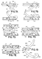
- FIGS. 7A through 7E show how the applier 80 is used in applying the clip 10.
- the clip 10 is in the open position with the general axes of the leg members forming an acute angle at the hinge, but the clip could be open as much as 90° or more.
- the jaws of the applier are biased open by an amount equal to the opening of the clip so that the flat surface 126 of jaw 92 and the flat surface 128 of jaw 90 slide over the bosses 72 and 74 of leg 14 and a portion of the outer surface 30 of leg 12 near the hook portion, respectively.
- each jaw The cut outs of each jaw are spaced apart from one another within the jaw by the channel of each jaw which is at least as wide as the width of the clip and the cut outs are disposed to receive the bosses.
- the concave cut outs keep the clips aligned and locked within the jaws during the closing.
- the concave cut outs 104 and 120 press against the bosses to begin closure of the clip.
- the channels 96 and 110 accommodate the body of the clip within the jaws during the closing process. As best seen in FIG. 7D, both leg members deflect under the forces exerted on the clip during closure to accommodate movement of the hook portion of leg member 12 around the rounded tip of leg member 14.
- FIG. 3 shows the clip closed about a vessel 300.
- the radius of curvature of the inner convex surface of second leg member 14 is substantially the same as the radius of curvature of the inner concave surface of first leg member 12. This causes a relatively even distribution across the width of the clamped vessel of the compressive forces being exerted by the clip leg members 12 and 14.
- the vessel 300 particularly if large or upon swelling, will exert a counter force against the legs of the clip after application tending to open up the clip.
- the outer concave surface reduces the thickness of the second leg member such that it will deflect and lengthen in response to forces by the clamped vessel tending to open the clip. Lengthening of the second leg member moves the distal end of the second leg member farther into the hook portion.
- the forces by the clamped vessel exerted on the first leg member will tend to shorten the first leg member moving the hook portion closer to the hinge and the distal end of the second leg member.
- This configuration provides for a more secure latching.
- the thickness of the second leg member is smaller than it would have been without the concave outer surface, and is substantially the same as the first leg member between its inner and opposite outer surface, the total deflection necessary to accommodate closing and clamping of the vessel is distributed between the two legs with a substantial amount of deflection being taken up by second leg member helping to enhance the security of the latching effect and avoid premature failure of either leg.
- the thickness of the second leg member in the center region is slightly larger than the thickness of the first leg member or corresponding center region in order that the second leg member will bend slightly less than the first leg member to avoid passing the flattening position from which unlatching is facilitated. Both leg members can be made with equal thickness, however.
- each leg member comprises a peninsular portion (56 and 58) which is formed by an extension of the inner surface of each leg member and which substantially extends back to the inner wall 50 of the hinge when the clip is closed.
- the only void left in the hinge region are the "C" shaped voids 60 and 62 which are on opposite sides of the peninsular portions from the vessel clamping inner surfaces of the leg members.
- the peninsular portions are formed spaced apart from the leg member portions coupled to the hinge portion to avoid the resistance to closing which would be created by compressing the leg members in the region of the hinge upon closing.
- the narrowed hinge is still strong because of the continuous curve formed by its inner and outer surfaces, and no void is accessible to trap the clamped vessel.
- FIG. 18 shows an alternate embodiment clip 310 which is identical to the clip 10 in FIGS. 1 through 3 except for the hinge portion 316.
- the clip 310 comprises curved first and second leg members 312 and 314 joined at their proximal ends by hinge portion 316.
- First leg member 312 has a concave inner surface 320 and curved hook portion 322 joined at its distal end.
- the inner surface 324 of second curved leg member 314 is convex and is adapted to be substantially parallel with concave inner surface 320 when the clip is closed, i.e., the radius of curvature of the convex surface 324 is substantially the same as the radius of curvature of the concave surface 320.
- Hinge portion 316 comprises an inner continuously curved concave surface 350 which joins the inner concave and convex surfaces 320 and 324, respectively, and an outer continuously curved surface 352 which joins outer convex and concave surfaces 330 and 338, respectively, and which is spaced apart from inner hinge concave surface 350.
- the hinge portion 316 further includes a curved slot 353 which is located between curved hinge surfaces 350 and 352, being positioned closer to concave hinge surface 350 than to convex hinge surface 352.
- the slot extends completely through the hinge portion 316 from side to side and its opposite ends 355 and 357 extend into the proximal ends of the leg members 312 and 314, respectively.
- the slot 353 provides added flexibility to the hinge 316 but the inner concave surface 350 prevents any portion of the clamped vessel from being trapped within the slot 353.
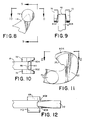
- FIGS. 8 through 12 show modifications to the clip which provide a means for guiding the clip into locking engagement.
- the inside opposing surfaces of the side bosses 72 and 74 at the tip of leg member 14 are provided with an outward taper 802 and 804, each of which extends away from the side of the second leg member and increases until the circumference of the boss is reached.
- the taper is present at the curved beveled surface 44 and decreases as the tip 46 is approached.
- the end of the hook portion 22 is tapered at 806 and 808 to narrow the outer surface as it approaches the flat 35 on the hook portion. See FIGS. 11 and 12. As the narrowed outer surface of the end of the hook portion slides along the curved beveled surface 44 it is received by the enlarged opening between the opposing surfaces of the lateral bosses 72 and 74 created by the tapers 802 and 804 thereon. As the hook portion continues to slide between the lateral bosses the opening due to the tapers on the bosses 72 and 74 narrows aligning the first leg member 12 with the second leg member 14.
- FIG. 13 is an alternate embodiment of the clip of FIGS. 1-3.
- the clip 10′ of FIG. 13 further includes a plurality of protrusions 1302 on the inner surface 20′ of the leg member 12′, while leg member 14′ includes a plurality of protrusions 1304 on its inner surface 24′.
- the protrusions are wedge shaped with the wedge opening up towards the hinge portion.
- the protrusions engage the tissue of the vessel being clamped and assist in preventing the vessel sliding laterally or longitudinally during or following clip closure. It is preferable that the clip clamp the vessel substantially across the vessel at 90° to the axis of the vessel.
- the vessel being dynamic may move or pulse and such movement may cause the clip to become misaligned degrading its performance or function.
- the protrusions help in preventing this.
- the clip of FIGS. 1 - 13 is preferably a single integral piece of molded plastic.
- the plastic material chosen is preferably one of the many relatively strong engineering plastics available today which are commonly used in surgical implant operations and are biocompatible.
- Two examples of suitable plastics are polyethylene terephthalate (PET) and polyoxymethylene. These are both thermoplastic materials that can be injection molded, extruded or otherwise thermally processed into shaped articles and filaments.
- PET polyethylene terephthalate
- PBT polybutylene terephthalate
- any plastic surgical clip such as a hemostatic clip
- the preferred embodiment clip can be made as small as seven millimeters in overall length in the closed position as measured from the back of the hinge to the outside of the hook portion. This is to be compared with a medium size metal hemostatic clip which is approximately six millimeters in length when closed.
- Each leg of the polymeric clip of the present invention has a maximum thickness in the order of 1.0 millimeters or less with a weight of about 0.015 grams, a volume of 0.01 cubic centimeters and an opening of 4 millimeters or more.
- the radius of curvature of the inner surface of the leg 12 starts out as 4.22 mm (0.166 inches) near the peninsular portion 56, changes to 5.64 mm (0.222 inches) at the center region up to the hook portion 22 where it changes to 1.32 mm (0.052 inches) and then to 0.18 mm (0.007 inches).
- the outer surface of the hook portion starting at its end 32 is 1.14 mm (0.045 inches) then 0.91 mm (0.036 inches).
- the radius of curvature changes from 2.74 mm (0.108 inches), to 6.25 mm (0.246 inches), to 4.34 mm (0.171 inches) near the hinge 16.
- the hinge's outer surface 52 has a radius of 1.07 mm (0.042 inches) until the outer concave surface 38 of the leg member 14 begins at the radius of 4.09 mm (0.161 inches) and then 5.87 mm (0.231 inches) near the tip 46 [radius of 0.08 mm (0.003 inches)].
- the radius of the curved beveled surface 44 is 1.12 mm (0.044 inches) up until the start of the convex inner surface 24 of leg member 14 which is 5.64 mm (0.222 inches) and then 4.22 mm (0.166 inches).
- the radii are provided to give an example of the degree of curvature of the clip and to show that the curved surfaces are generally continuous.
- the clip comprises a first leg member 212 with inner concave curved surface 220 and outer convex curved surface 230.
- the leg member comprise a hook portion 222 integrally formed at its distal end similar in function and shape to the hook portion 22 of clip 10.
- It further comprises a cylindrical socket portion 216 integrally formed at its proximal end.
- the cylindrical socket portion is approximately one half the thickness of the first leg member 212 as measured along the axis of the socket from one side of the leg member 212 to its opposite side.
- a first side of the cylindrical socket portion is in the same plane as the outer side 250 of the first leg member.
- the opening 251 through the socket 216 first becomes larger from this side for a distance along the axis of the socket until it abruptly narrows forming an interior annular ledge 252.
- the opening maintains a constant diameter for a distance at 254 when for a short distance it becomes larger and opens up at the opposite side 256 of the socket.
- Leg member 214 includes and inner convex surface 224 and an outer concave surface 238.
- the outer concave surface is joined with the tip 239 of the distal end of the leg 214 by a flat beveled surface 256.
- the leg member 214 includes an integrally formed enlarged cylinder 260 whose thickness along its axis is about one half the thickness of the leg member 214.
- the outside end surface of the cylinder is flush with or in the same plane as the outside surface 262 of the leg member 214.
- Integrally formed with the enlarged cylinder 260 is a smaller diameter cylinder 264, coaxial with cylinder 260 and extending away therefrom along the common axis.
- the end of the smaller cylinder 264 has a trapezoidal shape which forms an annular ledge 268 spaced apart from the end of the smaller cylinder.
- the cylindrical socket 216 of the first leg member 212 is adapted to receive the smaller diameter cylinder 264 in a snap like fit.
- the smaller cylinder passes through the socket with the ledge 268 of the end of the smaller cylinder compressed within the constant diameter portion 254 of the socket until the end passes the interior ledge 252.
- the end of the smaller cylinder snaps into place with the region of the socket formed by ledge 252 adapted to receive the trapezoidal portion of the smaller diameter cylinder 264.
- the ledge 252 engages the ledge 268 preventing the legs from being separated once they are snapped together.
- the completely circular, enlarged hinge formed by the structure just described provides a very strong hinge to withstand hinge failure particularly during application of the clip to a vessel.
Landscapes
- Health & Medical Sciences (AREA)
- Surgery (AREA)
- Life Sciences & Earth Sciences (AREA)
- General Health & Medical Sciences (AREA)
- Veterinary Medicine (AREA)
- Vascular Medicine (AREA)
- Engineering & Computer Science (AREA)
- Biomedical Technology (AREA)
- Heart & Thoracic Surgery (AREA)
- Medical Informatics (AREA)
- Molecular Biology (AREA)
- Animal Behavior & Ethology (AREA)
- Reproductive Health (AREA)
- Public Health (AREA)
- Nuclear Medicine, Radiotherapy & Molecular Imaging (AREA)
- Surgical Instruments (AREA)
- Clamps And Clips (AREA)
- Diaphragms For Electromechanical Transducers (AREA)
- Shaping By String And By Release Of Stress In Plastics And The Like (AREA)
- Finger-Pressure Massage (AREA)
- Materials For Medical Uses (AREA)
- Transition And Organic Metals Composition Catalysts For Addition Polymerization (AREA)
- Pharmaceuticals Containing Other Organic And Inorganic Compounds (AREA)
- Nitrogen Condensed Heterocyclic Rings (AREA)
Abstract
Description
- The present invention relates to surgical clips and clip appliers and more particularly to polymeric hemostatic clips and instruments for applying them.
- Surgical clips like hemostatic clips and aneurysm clips are often used in surgery to ligate vessels to stop the flow of blood. Surgical clips are also used to interrupt or occlude the oviduct or vas deferens in sterilization procedures. The clips are left in place permanently and within a period of time the ligated end of the vessel will close, that is, hemostasis or occlusion will occur.
- Metal clips having generally U or V shapes have been used for years. The most common metals are alloys of tantalum, titanium or stainless steel, all of which are deformed into a closed position about the vessel and because of the nature of the metal stay deformed and resist any force by the vessel to expand or open up.
- Metal clips cause a certain amount of interference with high technology diagnostic modalities, including Computer Tomography (CATSCAN) and Magnetic Resonance Imaging (MRI). In particular, the new and emerging MRI techniques place stringent demands on the non-interference properties of clips. For example, existing fast imaging techniques for MRI give rise to at least one order of magnitude in increased sensitivity to magnetic field inhomogenieties brought about by metallic clips. Field uniformities of one in 10⁵ are required but metal clips, particularly stainless steel clips, can reduce the homogeniety in the locality of the clip to the order of 10⁴ or less.
- To aggravate the situation even more recent developments in in vivo Magnetic Resonance Spectroscopy (MRS) create even greater demands on minimizing magnetic field interferences (field uniformities approximately one in 10⁷ required). Existing metal clips preclude the use of MRS data taken in the proximity of the metal clips. This region is as large as six clip diameters for titanium and tantalum and more than fifty clip diameters for stainless steel.
- To overcome the above problems, in recent years plastic clips have been introduced. These clips generally should be as small as possible, e.g., as small as their metal counterparts. Plastic clips require a latching means to keep the clip closed once they are clamped about the vessel since, unlike metal clips, they have insufficient resistance to the forces tending to open the vessels.
- Most of the new plastic clips now in the market are made of a biodegradable and absorbable polymeric material. Generally, the absorbable clips, owing to their comparatively high water sorption do not reflect the mechanical strength levels which are available from modern engineering plastics and therefore represent a size increase compromise in order to provide comparative strength. The use of high performance polymer materials permits increased design options for functional improvements.
- It is, therefore, desirable to produce a small, but secure, biocompatible and strong polymeric surgical clip.
- EP-A-0 086 640 is directed to a hemostatic clip made from an absorbable or non-absorbable biocompatible polymeric material with first and second leg members joined at their proximal ends by resilient hinge means and terminating at their distal ends in latch means. When pivoted about the hinge means, the distal end of the second leg member deflects and engages a hook member of the first leg member to lock the clip in a closed position. More particular, the second leg member with the hook member may be thin and pliable enough to be deflectable. However, no mention is made in this document of the possibility of producing a concave outer surface on the first leg member in order to be enabled to straighten in response to a vessel clamped between the vessel clamping surfaces.
- The surgical clip of the present invention is made of polymeric material and accordingly minimizes interference with high technology diagnostic modalities such as CATSCAN, MRI and MRS. At the same time, the clip is nearly as small as comparable metal clips, while maintaining sufficient strength and possessing high security in the clip's latching mechanism in the closed position. The clip is configured to provide a secure means of handling and application to avoid premature release from the applier.
- A surgical clip is provided which comprises first and second curved leg members joined at their proximal ends by a hinge means and disposed to be latched together in the closed position at their distal ends. The leg members each include curved, opposing inner surfaces which are substantially parallel in the closed position, the inner surface of the first leg being concave in shape. The first leg member further includes a hook portion joined at its distal end and curved toward said second leg member. The hook portion is disposed to engage the outer surface of the end of the second leg member when the clip is in the closed position. The outer surface of the second leg member opposite the inner convex surface is concave in shape. This configuration provides a more secure latching mechanism, since any forces by the clamped vessel tending to open the clip will force the second leg to lengthen and the first leg member to shorten moving the distal end of the second leg member into further engagement with the hook portion. Because the thickness of the second leg member is smaller than it would have been without the concave outer surface, the second leg member will deflect upon clamping or in response to the forces exerted on it by the clamped vessel and because the thickness of each leg between its inner and opposite outer surfaces between the hinge and distal end is substantially equal to the thickness of the other leg, the total deflection necessary to accommodate closing and clamping of the vessel is distributed between the two legs helping to avoid breakage or failure of either leg. In the preferred embodiment, the radius of curvature of the inner concave surface of the first leg member is the same as the radius of curvature of the inner convex surface of the second leg member. This provides a constant compressive force across the entire width of the vessel being clamped.
- The hinge means comprises a reduced thickness portion of the clip. The hinge means is formed by a continuous curve of large radius, with appropriate thickness which helps to reduce stress concentration in the hinge. The first and second leg members each further comprises a peninsular portion formed from an extension of the inner surface of the leg member. The peninsular portions extend substantially to the inner surface of the hinge means when the clip is in the closed position, preventing any portion of the clamped vessel from being located in the hinge region where total occlusion might be avoided.
- In another embodiment of the hinge, the hinge comprises a curved slot which extends through the hinge from side to side positioned between the inner concave and outer convex curved surfaces of the hinge, preferably located closer to the concave surface than the convex surface. The slotted hinge increases flexibility of the hinge beyond that of a hinge with the same thickness, but not having the slot. The slot, however, is isolated from the vessel clamped between the leg inner surfaces by the interior concave surface of the hinge which avoids trapping of any portion of the vessel in the hinge region where failure to occlude the vessel would have been possible.
- The inner and outer surfaces of the hook portion are substantially continuously curved to prevent excessive stress concentration occurring at corners or small radius points in the hook portion.
- The clip further comprises means for allowing the clip to be engaged by a suitable forceps type applier comprising at least a pair of bosses located on the sides of the first leg member intermediate the hinge means and the hook portion and a pair of bosses also located on the sides of the second leg member at the distal end and so disposed as to extend beyond the end of the second leg member to provide two parallel and separately spaced surfaces which prevent lateral movement of the leg members relative to one another when the clip is closed. The bosses are used by the applier in holding and applying the clip.
- The sides of the end of the hook portion are tapered to reduce the thicknesses of the outer surface of the end to provide alignment during the initial stages of clip closure.
- The clip of the present invention may also include a plurality of protrusions on the inner surfaces of the leg members to aid in retention of the clamped vessel. The protrusions may be ratchet type, wedge shaped, to provide one way vascular movement into, but not out of, the clip.
- A ligating clip applying instrument for applying two legged ligating clips having means for engaging the bosses located on the sides of the legs is also provided. The jaws of the instrument include a channel to receive the clip and a concave cut out near the end of each jaw in a wall on both sides of the channel. Each wall also includes an arcuate wall portion adjacent to and on the outside of the cut out.
- The instrument further comprises a protrusion in the floor of each of said channels which is directed toward the opposite jaw, the protrusion being located proximally of the concave cut outs. Each protrusion engages a leg of the clip to assist in forcing the legs toward one another as the jaws are closed.
- FIG. 1 is a greatly enlarged perspective view of the surgical clip of the present invention.
- FIGS. 2A through 2D are enlarged side elevational views of the clip and greatly enlarged portions of the clip.
- FIG. 3 shows the clip of FIG. 1 applied to a body vessel.
- FIG. 4 illustrates an enlarged planar elevational view of a forceps type applier useful with the clip of the present invention.
- FIG. 5 is a greatly enlarged perspective view of a break away of a first jaw of the applier of FIG. 4.
- FIG. 5A is a bottom planar view of the first jaw of FIG. 5.
- FIG. 6 is a greatly enlarged perspective view of a break away of a second jaw of the applier of FIG. 4.
- FIG. 6A is a bottom planar view of the second jaw of FIG. 6.
- FIGS. 7A to 7E illustrate the use of the applier of FIGS. 4 to 6A in applying the clip of the present invention.
- FIG. 8 is an enlarged side elevational view of an alternate embodiment distal end of a leg member of the clip of FIG. 1.
- FIG. 9 is a front elevational view of the distal end of FIG. 8 taken along the lines and arrows 9 - 9 in FIG. 8.
- FIG. 10 is a top view of the distal end of FIG. 8 taken along the lines and arrows 10 - 10 in FIG. 8.
- FIG. 11 is a greatly enlarged side elevational view of an alternate embodiment hook portion of the clip of FIG. 1
- FIG. 12 is a top view of the hook portion of FIG. 11 taken along the lines and arrows 12 - 12 in FIG. 11.
- FIG. 13 is a greatly enlarged perspective view of a second alternate embodiment of the clip of FIG. 1.
- FIG. 14 is a greatly enlarged perspective view of a third alternate embodiment of the clip of FIG. 1 shown in the closed position.
- FIG. 15 is a perspective view of a first leg member of the clip of FIG. 14.
- FIG. 16 is a perspective view of a second leg member of the clip of FIG. 14.
- FIG. 17 is a reduced size elevational planar view in partial cross section of the first leg member of FIG. 15.
- FIG. 18 is a greatly enlarged side elevational view of a fourth alternate embodiment of the clip of FIG. 1.
- Referring now to FIGS. 1, 2A - 2D and 3, a preferred embodiment surgical clip designated generally 10 is shown. It comprises a first
curved leg member 12 and a secondcurved leg member 14 joined at their proximal ends by ahinge portion 16.First leg member 12 has a concaveinner surface 20 and acurved hook portion 22 joined at its distal end. Theinner surface 24 of secondcurved leg member 14 is convex and is adapted to be substantially parallel with concaveinner surface 20 when the clip is closed, i.e; the radius of curvature of the concaveinner surface 20 is substantially the same as innerconvex surface 24. Thehook portion 22 is curved toward the distal end ofsecond leg member 14. - The inner and
outer surfaces hook portion 22 are continuously curved with theouter surface 28 continuing from the convexouter surface 30 of the first leg member with decreasing radius of curvature while theinner surface 26 continues from the innerconcave surface 20 of thefirst leg member 12 in a decreasing radius of curvature to a constant terminal radius of curvature. In the preferred embodiment the thickness of the first leg member between its inner andouter surfaces outer surface - The
second leg member 14 has a banana like profile along its length between its innerconvex surface 24 and outerconcave surface 38. The thickness of the distal end has a rapid reduction in thickness because of the change in radius of curvature of itsinner surface 24 at 42 to form a curved innerbeveled surface 44 terminating in atip 46 and the relatively flatbeveled surface 48 joining the outerconcave surface 38 to thetip 46. - The thickness of the
second leg member 14 between its inner andouter surfaces hinge portion 16 and its distal end may vary by ten to twenty percent with the leg being thickest at its center region. Generally the thickness of thesecond leg 14 is substantially the same as the thickness of thefirst leg 12 except for this variation in the center where the second leg may be slightly thicker. The thickness of thefirst leg 12 could be increased, however, in the center region to match the thickness of the first leg by varying the outerconvex surface 30 of thefirst leg 12 but the radius of curvature of the concaveinner surface 20 remains equal to the radius of curvature of the convexinner surface 24 of thesecond leg member 14. The thickness of thesecond leg member 14 being slightly thicker in the center causes the first leg member to deflect a little more than the second leg member when the clip is being clamped about a vessel, but the second leg member is disposed because of its outer concave surface to deflect substantially during closure so that total defection of the legs necessary to clamp a vessel and latch the clip is being shared about equally by the legs. - The
hinge portion 16 has a substantially reduced thickness between its inner andouter surfaces leg members outer surface 52 of thehinge portion 16 connects theouter surfaces leg members Leg members peninsular portions inner surface 50 of thehinge portion 16. The peninsular portions are spaced apart from the proximal ends of the leg members coupled to the hinge portion and they are formed by an extension of theinner surfaces peninsular portions inner surface 50 of thehinge portion 16 to form the letter "C" shapedopenings -
Leg member 12 includes a pair ofcylindrical bosses leg member 12 intermediate thehook portion 22 and thehinge portion 16, but closer to thehook portion 22 in the preferred embodiment. The bosses extend laterally away from the leg member. -
Leg member 14 includes a pair ofcylindrical bosses tip 46 on opposite sides of theleg member 14 and extending laterally away therefrom. In the preferred embodiment, the coaxial center line of thebosses leg member 14. See FIG. 2C where theboss 74 is removed showing the relationship of thetip 46 to the center ofboss 72. Thebosses surfaces - FIG. 4 shows a forceps
type clip applier 80 which includes twohandles hinge 86. The handles are biased into an open position by thespring 88. Thehandles hinge 86 to formjaws - FIG. 5 is an enlarged break away of a portion of the
jaw 90 while FIG. 5A is a planar view of thejaw 90 of FIG. 5 both showing the details of its construction. Thejaw 90 includes achannel 96 which extends from aposition 97 rearward of the tip of the jaw towards the tip. The thickness of theoutside walls 98 of the channel widen as they approach the end of the jaw to form arcuateoutside walls 100 of the end of the jaw and inwardadjacent walls 102 with rearwardly directedsloped surfaces 103 andconcave cut outs 104. The inner surfaces of thewalls 102 are contiguous with and in the same plane as the inner surfaces of thewalls 98 which form thechannel 96. Where thewalls 98 widen to form the outsidearcuate walls 100 andadjacent walls 102, thecut outs 104 extend beyond the top surfaces of thewalls 98 toward the opposite jaw to formrounded shoulders 105. The adjacentarcuate walls 100 also are raised above the top surfaces ofwalls 98 by the same amount. Thefloor 99 ofchannel 96 is spaced apart and parallel with the top surfaces ofwalls 98 of the jaw along a portion extending from therearward terminus 97 of the channel until the floor extends towards the opposite jaw alongramp 101 to form aprotrusion 108 located just as thecut outs 104 extend above the top surfaces ofwalls 98. Theprotrusion 108 drops straight off to aflat portion 128 of the jaw which flat portion extends to the tip. The jaw has a flat outerbottom surface 106. - FIG. 6 is an enlarged break away of a portion of
jaw 92 while FIG. 6A is a planar view of thejaw 92 of FIG. 6 both showing the details of its construction, which are identical to the construction ofjaw 90. The jaw includes a channel 110 which extends from aposition 112 rearward of the tip of the jaw toward the tip. Theoutside walls 114 of the channel widen as they approach the end of the jaw to form arcuateoutside walls 116 of the end of the jaw and inwardadjacent walls 118 with rearwardly directedsloped surfaces 119 andconcave cut outs 120. The inner surfaces of thewalls 118 are contiguous with and in the same plane as the inner surfaces of thewalls 114 which form the channel 110. Where thewalls 114 widen to formwalls cut outs 120 extend towards the opposite jaw beyond the top surfaces ofwalls 114 to formrounded shoulders 121. Thearcuate walls 116 extend beyond the top surface by the same amount. The floor 111 of channel 110 is spaced apart and parallel with the top surface ofwalls 114 of the jaw along a portion extending from therearward terminus 112 of the channel until the floor extends towards the opposite jaw alongramp 125 to form aprotrusion 124 located just as thecut outs 121 extend above the top surfaces ofwalls 114. Theprotrusion 124 drops straight off to aflat portion 126 of the jaw which extends to the tip. The jaw has a flat outerbottom surface 122. - FIGS. 7A through 7E show how the
applier 80 is used in applying theclip 10. Theclip 10 is in the open position with the general axes of the leg members forming an acute angle at the hinge, but the clip could be open as much as 90° or more. The jaws of the applier are biased open by an amount equal to the opening of the clip so that theflat surface 126 ofjaw 92 and theflat surface 128 ofjaw 90 slide over thebosses leg 14 and a portion of theouter surface 30 ofleg 12 near the hook portion, respectively. As the applier is moved in the direction ofarrow 700 in FIG 7A, thebosses inclined surfaces walls cut outs - The cut outs of each jaw are spaced apart from one another within the jaw by the channel of each jaw which is at least as wide as the width of the clip and the cut outs are disposed to receive the bosses. The concave cut outs keep the clips aligned and locked within the jaws during the closing. The
concave cut outs - After the boss pairs 72, 74 and 68, 70 seat themselves in the concave cut outs, the raised
shoulders jaws leg members outside surface 32 of thehook portion 22 engages theinner surface 24 ofleg member 14 near thecurved bevel surface 44. See FIG. 7C. As the leg members continue to be pressed together, the rounded outside surface of thehook portion 22 slides along thecurved bevel surface 44 and around tip 46 (FIG. 7D) until theflat surface 35 on the end of thehook portion 22 engages the flatbeveled surface 48 on the outside of theleg member 14 closing the clip (FIG. 7E). Thechannels 96 and 110 accommodate the body of the clip within the jaws during the closing process. As best seen in FIG. 7D, both leg members deflect under the forces exerted on the clip during closure to accommodate movement of the hook portion ofleg member 12 around the rounded tip ofleg member 14. - FIG. 3 shows the clip closed about a
vessel 300. In the preferred embodiment the radius of curvature of the inner convex surface ofsecond leg member 14 is substantially the same as the radius of curvature of the inner concave surface offirst leg member 12. This causes a relatively even distribution across the width of the clamped vessel of the compressive forces being exerted by theclip leg members vessel 300, particularly if large or upon swelling, will exert a counter force against the legs of the clip after application tending to open up the clip. The outer concave surface reduces the thickness of the second leg member such that it will deflect and lengthen in response to forces by the clamped vessel tending to open the clip. Lengthening of the second leg member moves the distal end of the second leg member farther into the hook portion. At the same time, the forces by the clamped vessel exerted on the first leg member will tend to shorten the first leg member moving the hook portion closer to the hinge and the distal end of the second leg member. This configuration provides for a more secure latching. Also, because the thickness of the second leg member is smaller than it would have been without the concave outer surface, and is substantially the same as the first leg member between its inner and opposite outer surface, the total deflection necessary to accommodate closing and clamping of the vessel is distributed between the two legs with a substantial amount of deflection being taken up by second leg member helping to enhance the security of the latching effect and avoid premature failure of either leg. The thickness of the second leg member in the center region is slightly larger than the thickness of the first leg member or corresponding center region in order that the second leg member will bend slightly less than the first leg member to avoid passing the flattening position from which unlatching is facilitated. Both leg members can be made with equal thickness, however. - Since the objective of the clip is to occlude or seal off the vessel, it is imperative that the entire vessel be occluded. In some clips it is possible that a portion of the vessel becomes trapped in a void adjacent the inner surface of the hinge portion and is not occluded by the clip leg members. Such an occurrence would allow blood or fluid to pass through the unoccluded portion of the vessel. To avoid this on the clip of the present invention, each leg member comprises a peninsular portion (56 and 58) which is formed by an extension of the inner surface of each leg member and which substantially extends back to the
inner wall 50 of the hinge when the clip is closed. The only void left in the hinge region are the "C" shapedvoids - With reference to the hinge portion, FIG. 18 shows an
alternate embodiment clip 310 which is identical to theclip 10 in FIGS. 1 through 3 except for thehinge portion 316. Theclip 310 comprises curved first andsecond leg members hinge portion 316.First leg member 312 has a concaveinner surface 320 andcurved hook portion 322 joined at its distal end. Theinner surface 324 of secondcurved leg member 314 is convex and is adapted to be substantially parallel with concaveinner surface 320 when the clip is closed, i.e., the radius of curvature of theconvex surface 324 is substantially the same as the radius of curvature of theconcave surface 320. Theouter surface 338 of thesecond leg member 314 is concave between the hinge portion and its distal end.Hinge portion 316 comprises an inner continuously curvedconcave surface 350 which joins the inner concave andconvex surfaces curved surface 352 which joins outer convex andconcave surfaces concave surface 350. Thehinge portion 316 further includes acurved slot 353 which is located between curved hinge surfaces 350 and 352, being positioned closer toconcave hinge surface 350 than toconvex hinge surface 352. The slot extends completely through thehinge portion 316 from side to side and its opposite ends 355 and 357 extend into the proximal ends of theleg members slot 353 provides added flexibility to thehinge 316 but the innerconcave surface 350 prevents any portion of the clamped vessel from being trapped within theslot 353. - The inner surfaces of the
side bosses tip 46 of theleg member 14 prevent the hook member andleg member 14 from moving laterally relative to one another, once the clip is closed. - By providing a continuous relatively large radii of curvature to both the inner and outer surfaces of the hinge portion and the hook portion, sharp interior corners which create unwanted stress concentration, which can lead to clip failure, are eliminated.
- FIGS. 8 through 12 show modifications to the clip which provide a means for guiding the clip into locking engagement. The inside opposing surfaces of the
side bosses leg member 14 are provided with anoutward taper beveled surface 44 and decreases as thetip 46 is approached. - The end of the
hook portion 22 is tapered at 806 and 808 to narrow the outer surface as it approaches the flat 35 on the hook portion. See FIGS. 11 and 12. As the narrowed outer surface of the end of the hook portion slides along the curvedbeveled surface 44 it is received by the enlarged opening between the opposing surfaces of thelateral bosses tapers bosses first leg member 12 with thesecond leg member 14. - FIG. 13 is an alternate embodiment of the clip of FIGS. 1-3. The
clip 10′ of FIG. 13 further includes a plurality ofprotrusions 1302 on theinner surface 20′ of theleg member 12′, whileleg member 14′ includes a plurality ofprotrusions 1304 on itsinner surface 24′. The protrusions are wedge shaped with the wedge opening up towards the hinge portion. The protrusions engage the tissue of the vessel being clamped and assist in preventing the vessel sliding laterally or longitudinally during or following clip closure. It is preferable that the clip clamp the vessel substantially across the vessel at 90° to the axis of the vessel. The vessel being dynamic may move or pulse and such movement may cause the clip to become misaligned degrading its performance or function. The protrusions help in preventing this. - The clip of FIGS. 1 - 13 is preferably a single integral piece of molded plastic. The plastic material chosen is preferably one of the many relatively strong engineering plastics available today which are commonly used in surgical implant operations and are biocompatible. Two examples of suitable plastics are polyethylene terephthalate (PET) and polyoxymethylene. These are both thermoplastic materials that can be injection molded, extruded or otherwise thermally processed into shaped articles and filaments. An alternate, molding grade polyester, polybutylene terephthalate (PBT) can also be used.
- As mentioned earlier it is preferable that any plastic surgical clip, such as a hemostatic clip, be as small as its metal equivalent. The preferred embodiment clip can be made as small as seven millimeters in overall length in the closed position as measured from the back of the hinge to the outside of the hook portion. This is to be compared with a medium size metal hemostatic clip which is approximately six millimeters in length when closed. Each leg of the polymeric clip of the present invention has a maximum thickness in the order of 1.0 millimeters or less with a weight of about 0.015 grams, a volume of 0.01 cubic centimeters and an opening of 4 millimeters or more.
- In the preferred embodiment, the radius of curvature of the inner surface of the
leg 12 starts out as 4.22 mm (0.166 inches) near thepeninsular portion 56, changes to 5.64 mm (0.222 inches) at the center region up to thehook portion 22 where it changes to 1.32 mm (0.052 inches) and then to 0.18 mm (0.007 inches). The outer surface of the hook portion starting at itsend 32 is 1.14 mm (0.045 inches) then 0.91 mm (0.036 inches). As the hook portion ends and theouter surface 30 ofleg member 12 continues towards the hinge the radius of curvature changes from 2.74 mm (0.108 inches), to 6.25 mm (0.246 inches), to 4.34 mm (0.171 inches) near thehinge 16. The hinge'souter surface 52 has a radius of 1.07 mm (0.042 inches) until the outerconcave surface 38 of theleg member 14 begins at the radius of 4.09 mm (0.161 inches) and then 5.87 mm (0.231 inches) near the tip 46 [radius of 0.08 mm (0.003 inches)]. The radius of the curvedbeveled surface 44 is 1.12 mm (0.044 inches) up until the start of the convexinner surface 24 ofleg member 14 which is 5.64 mm (0.222 inches) and then 4.22 mm (0.166 inches). The radii are provided to give an example of the degree of curvature of the clip and to show that the curved surfaces are generally continuous. The centers of the radii, even for the concave and convex surfaces, such as, the inner and outer surfaces of the leg members, are not generally the same. While these radii reflect the radii for the preferred embodiment clip, it should be understood that variations or changes from these radii are encompassed by the present invention curved clip. - Referring now to FIGS. 14 through 17, an alternate embodiment
polymeric clip 200 made from two pieces is shown. The clip comprises afirst leg member 212 with inner concavecurved surface 220 and outer convexcurved surface 230. The leg member comprise ahook portion 222 integrally formed at its distal end similar in function and shape to thehook portion 22 ofclip 10. It further comprises acylindrical socket portion 216 integrally formed at its proximal end. The cylindrical socket portion is approximately one half the thickness of thefirst leg member 212 as measured along the axis of the socket from one side of theleg member 212 to its opposite side. A first side of the cylindrical socket portion is in the same plane as theouter side 250 of the first leg member. Theopening 251 through thesocket 216 first becomes larger from this side for a distance along the axis of the socket until it abruptly narrows forming an interiorannular ledge 252. The opening maintains a constant diameter for a distance at 254 when for a short distance it becomes larger and opens up at theopposite side 256 of the socket. -
Leg member 214 includes and innerconvex surface 224 and an outerconcave surface 238. The outer concave surface is joined with thetip 239 of the distal end of theleg 214 by a flatbeveled surface 256. At the proximal end theleg member 214 includes an integrally formedenlarged cylinder 260 whose thickness along its axis is about one half the thickness of theleg member 214. The outside end surface of the cylinder is flush with or in the same plane as the outside surface 262 of theleg member 214. Integrally formed with theenlarged cylinder 260 is asmaller diameter cylinder 264, coaxial withcylinder 260 and extending away therefrom along the common axis. The end of thesmaller cylinder 264 has a trapezoidal shape which forms anannular ledge 268 spaced apart from the end of the smaller cylinder. - The
cylindrical socket 216 of thefirst leg member 212 is adapted to receive thesmaller diameter cylinder 264 in a snap like fit. When the end of the smaller cylinder is pressed into the enlarged opening of the socket in theside 256 ofleg 212, the smaller cylinder passes through the socket with theledge 268 of the end of the smaller cylinder compressed within theconstant diameter portion 254 of the socket until the end passes theinterior ledge 252. At that point the end of the smaller cylinder snaps into place with the region of the socket formed byledge 252 adapted to receive the trapezoidal portion of thesmaller diameter cylinder 264. Theledge 252 engages theledge 268 preventing the legs from being separated once they are snapped together. The completely circular, enlarged hinge formed by the structure just described provides a very strong hinge to withstand hinge failure particularly during application of the clip to a vessel. - While the embodiments of the surgical clip described herein above are particularly adapted for hemostatic application, they may also have other applications, e.g. as oviduct or vas deferens clips.
Claims (21)
- A polymeric surgical clip comprising first and second curved leg members (12,14) joined at their proximal ends by a resilient hinge means (16), each leg member having a vessel clamping inner surface (20,24) and an opposite outer surface, said vessel clamping inner surface being in opposition to the vessel clamping inner surface of the other leg member, said first leg member (12) terminating at its distal end in a deflectable hook member (22) curved toward said second leg member, said second leg member (14) terminating at its distal end in a complimentary locking portion (46) to said hook member whereby when said first and second leg members are moved from an open position to a closed position about said hinge means (16), the hook member deflects about the distal end of said second leg member to lock the clip in a closed position, the inner surface (20) of the first leg member (12) having a concave radius of curvature between the hinge means and the hook member, the inner surface (24) of the second leg member (14) having a convex radius of curved between the hinge means and its distal end, characterized in that the outer surface (38) of said second leg member (14) has a concave radius of curvature between the hinge means and its distal end.
- The clip of Claim 1 wherein the outer surface (30) of said first leg member (12) has a convex radius of curvature.
- The clip of Claim 1 or 2 wherein the thickness of said first leg member (12) between said inner and outer surfaces between the hinge portion and the hook member is substantially the same as the thickness of said second leg member (14) between said inner and outer surfaces between the hinge portion (16) and its distal end.
- The clip of any of Claims 1 to 3 wherein the radius of curvature of said inner concave surface of said first leg member (12) is substantially equal to the radius of curvature of said inner convex surface of said second leg member (14).
- The surgical clip of any of Claims 1 to 4 wherein said hinge means (16) comprises a portion of said clip which has a reduced thickness compared to the thickness of said first and second leg members (12,14) and whose outer surface forms a continuous curve with the outer surfaces of said first and second leg members at said hinge means.
- The surgical clip of any of Claims 1 to 5 wherein said first and second leg members each comprises a peninsular portion (56 and 58, resp.) spaced apart from the hinge means (16) where the leg member is coupled to the hinge means and formed from an extension of the interior surface of the leg member which interior surface extends substantially to the inner surface of the hinge means when said clip is in the closed position.
- The surgical clip of any of Claims 1 to 6 wherein said hinge means comprises a portion of said clip having an outer curved surface (52) which forms a continuous curve with the outer surfaces of said first and second leg members and an inner curved surface (50) spaced apart from the hinge means outer surface, said hinge means inner curved surface forming a continuous curve with the inner surfaces of said first and second leg members free of any interior corners in said hook means.
- The clip of any of Claims 1 to 7 wherein said hinge means comprises a curved slot (353) between said hinge means inner and outer curved surfaces, the outer surface of said slot being concave to said slot and the inner surface of said slot being convex to said slot.
- The clip of Claim 8 wherein said slot (353) is closer to said hinge means inner concave surface than said hinge means outer convex surface.
- The surgical clip of any of Claims 1 to 9 wherein said clip comprises means (68,70,72,74) coupled to said first and second leg members for engagement with a suitable clip applier for applying said clips.
- The surgical clip of Claim 10 wherein said engagement means comprises a pair of bosses (68,70) joined to opposite sides of said first leg member (12) intermediate said hinge means and said hook portion, and a pair of bosses (72,74) joined to opposite sides of said second leg member (14) at the distal end of said second leg member, said opposite sides of said first and second leg members extending between said leg member inner and outer surfaces.
- The surgical clip of Claim 11 wherein a portion of said pair of bosses (72,74) joined to said second leg member (14) extend longitudinally beyond the distal end to form substantially parallel and spaced apart surfaces which prevent lateral movement of said first and second leg members relative to one another when the clip is in the closed position.
- The clip of Claim 11 or 12 wherein the sides of the end of the hook portion (22) are tapered towards one another to reduce the thickness of the hook portion and the inner surfaces of the bosses (72,74) on said second leg member (14) in the extended portion are tapered away from the second leg to receive the tapered portion of the hook portion to guide the clip into the closed position.
- The clip of any of Claims 1 to 13 wherein the inner surfaces of said clip each comprise a plurality of protrusions (1302,1304) for providing improved vessel retention during closure of the clips.
- The clip of Claim 14 where each of said protrusions (1302,1304) is a wedge shaped opening toward said hinge means.
- The clip of any of Claims 1 to 15 wherein said hinge means (16) is integrally formed with said first and second leg members (12,14) and said hook portion (22) is integrally formed with said first leg member (12).
- The clip of any of Claims 1 to 16 wherein said clip comprises a cylindrically shaped socket (216) integrally formed within the proximal end of said first leg member and a protruding cylinder (264) integrally formed on the proximal end of said second leg member, said socket adapted to receive said protruding cylinder in a snap on fit.
- A ligating clip applying instrument for applying two legged ligating clips according to any one of claims 1 to 17 having engagement means (68,70,72,74) on the lateral sides of said legs comprising: a pair of handles (82,84) pivoted about a hinge (86) point and extending beyond the hinge point to form a pair of clip closing jaws (90,92) having opposing inner faces, each of said jaws having a recessed clip receiving channel (96) in the inner face thereof extending from the tip of said jaw rearward toward said hinge point, said channel having a length at least equal to the length of the clip to be applied by the instrument; and each of said jaws comprising means for engaging said clip engagement means (68,70,72,74).
- The instrument of Claim 18 wherein said means for engagement comprises each wall on either side of said channel (96) in each jaw comprising a concave cut out near the end of said jaw and an arcuate wall portion adjacent to and on the outside of said cut out.
- The instrument of Claim 19 wherein the back wall of each concave cut out protrudes away from the channel (96) in the direction of said opposing jaw and the height of said adjoining arcuate wall portion is substantially equal to the height of said protruding back wall.
- The instrument of any of Claims 18 to 20 wherein the bottom of the channel (96) in each of said jaws forms a protrusion directed toward said opposed jaw between the portions of said cut outs which protrude toward said opposite jaw (90,92).
Applications Claiming Priority (4)
| Application Number | Priority Date | Filing Date | Title |
|---|---|---|---|
| US11259987A | 1987-10-26 | 1987-10-26 | |
| US112599 | 1987-10-26 | ||
| US07/206,143 US4834096A (en) | 1987-10-26 | 1988-06-13 | Plastic ligating clips |
| US206143 | 1988-06-13 |
Publications (3)
| Publication Number | Publication Date |
|---|---|
| EP0314064A2 EP0314064A2 (en) | 1989-05-03 |
| EP0314064A3 EP0314064A3 (en) | 1990-05-30 |
| EP0314064B1 true EP0314064B1 (en) | 1994-12-28 |
Family
ID=26810139
Family Applications (1)
| Application Number | Title | Priority Date | Filing Date |
|---|---|---|---|
| EP88117750A Expired - Lifetime EP0314064B1 (en) | 1987-10-26 | 1988-10-25 | Plastic ligating clips |
Country Status (11)
| Country | Link |
|---|---|
| US (1) | US4834096A (en) |
| EP (1) | EP0314064B1 (en) |
| AT (1) | ATE116127T1 (en) |
| AU (1) | AU615225B2 (en) |
| CA (1) | CA1312249C (en) |
| DE (1) | DE3852609T2 (en) |
| DK (1) | DK592588A (en) |
| ES (1) | ES2068820T3 (en) |
| FI (1) | FI884938A7 (en) |
| NO (1) | NO884749L (en) |
| NZ (1) | NZ226467A (en) |
Cited By (3)
| Publication number | Priority date | Publication date | Assignee | Title |
|---|---|---|---|---|
| WO2013059826A1 (en) | 2011-10-20 | 2013-04-25 | Atsina Surgical, Llc | Ligation clip |
| US11432823B2 (en) | 2019-07-17 | 2022-09-06 | Grena Usa Llc | Ligating clip cartridge |
| US11744595B2 (en) | 2020-05-11 | 2023-09-05 | Grena Usa Llc | Ligating clip |
Families Citing this family (572)
| Publication number | Priority date | Publication date | Assignee | Title |
|---|---|---|---|---|
| JPH01310654A (en) * | 1988-06-09 | 1989-12-14 | Shigekiyo Fujita | Cerebral aneurysm clip |
| US5062846A (en) * | 1989-03-28 | 1991-11-05 | Edward Weck Incorporated | Penetrating plastic ligating clip |
| US5171252A (en) * | 1991-02-05 | 1992-12-15 | Friedland Thomas W | Surgical fastening clip formed of a shape memory alloy, a method of making such a clip and a method of using such a clip |
| GR1002308B (en) * | 1991-06-18 | 1996-05-09 | Ethicon Inc. | Endoscopic suture clip. |
| US5201900A (en) * | 1992-02-27 | 1993-04-13 | Medical Scientific, Inc. | Bipolar surgical clip |
| US5282811A (en) * | 1992-04-16 | 1994-02-01 | Cook Pacemaker Corporation | Two part surgical ligating clip, applicator and method of use |
| US5279416A (en) * | 1992-06-05 | 1994-01-18 | Edward Weck Incorporated | Ligating device cartridge with separable retainer |
| US5234449A (en) * | 1992-07-16 | 1993-08-10 | Ethicon, Inc. | Suture clip with reduced hinge mass |
| US5342373A (en) * | 1992-09-14 | 1994-08-30 | Ethicon, Inc. | Sterile clips and instrument for their placement |
| US5464416A (en) * | 1992-11-10 | 1995-11-07 | Ethicon, Inc. | Ligating clip |
| US5858018A (en) * | 1993-08-25 | 1999-01-12 | Apollo Camera, Llc | Low profile tool for applying spring action ligation clips |
| US5833700A (en) * | 1995-03-15 | 1998-11-10 | Ethicon Endo-Surgery, Inc. | Sterile occlusion fasteners and instrument and method for their placement |
| US5900451A (en) * | 1997-05-15 | 1999-05-04 | Reichhold Chemicals, Inc. | Collaidally stabilized butadiene emulsions |
| US6241740B1 (en) | 1998-04-09 | 2001-06-05 | Origin Medsystems, Inc. | System and method of use for ligating and cutting tissue |
| US6193732B1 (en) | 1999-01-08 | 2001-02-27 | Cardiothoracic System | Surgical clips and apparatus and method for clip placement |
| US6350269B1 (en) | 1999-03-01 | 2002-02-26 | Apollo Camera, L.L.C. | Ligation clip and clip applier |
| US7427292B2 (en) * | 2001-05-16 | 2008-09-23 | Michael Sachs | Maximal nasal internal support system |
| CA2451102C (en) * | 2001-07-09 | 2009-09-15 | Tyco Healthcare Group Lp | Right angle clip applier apparatus and method |
| US6824547B2 (en) | 2001-07-13 | 2004-11-30 | Pilling Weck Incorporated | Endoscopic clip applier and method |
| EP2813186B1 (en) | 2002-04-22 | 2020-01-01 | Covidien LP | Endoscopic surgical clip |
| EP1496804A4 (en) * | 2002-04-22 | 2007-04-18 | Tyco Healthcare | Endoscopic surgical clip |
| US8231637B2 (en) * | 2002-07-26 | 2012-07-31 | Second Sight Medical Products, Inc. | Surgical tool for electrode implantation |
| US7131977B2 (en) * | 2002-08-27 | 2006-11-07 | Pilling Weck Incorporated | Apparatus and method for removing a clip |
| US7211091B2 (en) * | 2002-08-27 | 2007-05-01 | Pilling Weck Incorporated | Fingertip-actuated surgical clip applier and related methods |
| US6880699B2 (en) * | 2002-08-27 | 2005-04-19 | Pilling Weck Incorporated | Cartridge for holding asymmetric surgical clips |
| USD494271S1 (en) | 2002-08-28 | 2004-08-10 | Pilling Weck Incorporated | Automatic clip applier |
| USD490188S1 (en) | 2002-08-28 | 2004-05-18 | Pilling Weck Incorporated | Finger tip clip applier |
| US6863675B2 (en) * | 2002-09-20 | 2005-03-08 | Pilling Weck Incorporated | Ligating clip with integral penetrating hook |
| EP1555007A4 (en) * | 2002-10-23 | 2007-08-15 | Jms Co Ltd | Clip for dividing two liquids |
| US7678125B2 (en) * | 2002-11-12 | 2010-03-16 | Apollo Camera, L.L.C. | Surgical ligation clip |
| US7052504B2 (en) * | 2002-11-19 | 2006-05-30 | Teleflex Incorporated | Automated-feed surgical clip applier and related methods |
| US7211092B2 (en) * | 2002-11-19 | 2007-05-01 | Pilling Weck Incorporated | Automated-feed surgical clip applier and related methods |
| EP3170459A1 (en) | 2003-03-11 | 2017-05-24 | Covidien LP | Clip applying apparatus with angled jaw |
| US9060770B2 (en) | 2003-05-20 | 2015-06-23 | Ethicon Endo-Surgery, Inc. | Robotically-driven surgical instrument with E-beam driver |
| US20070084897A1 (en) | 2003-05-20 | 2007-04-19 | Shelton Frederick E Iv | Articulating surgical stapling instrument incorporating a two-piece e-beam firing mechanism |
| GB2402340B (en) * | 2003-06-06 | 2007-12-12 | Biomet Merck Ltd | Surgical device |
| US8172870B2 (en) * | 2003-06-09 | 2012-05-08 | Microline Surgical, Inc. | Ligation clip applier |
| WO2005034763A1 (en) | 2003-09-11 | 2005-04-21 | Nmt Medical, Inc. | Devices, systems, and methods for suturing tissue |
| US7572266B2 (en) * | 2003-10-21 | 2009-08-11 | Young Wayne P | Clip applier tool having a discharge configuration |
| WO2005046487A1 (en) | 2003-11-06 | 2005-05-26 | Nmt Medical, Inc. | Transseptal puncture apparatus |
| US8292910B2 (en) | 2003-11-06 | 2012-10-23 | Pressure Products Medical Supplies, Inc. | Transseptal puncture apparatus |
| US7326223B2 (en) * | 2004-01-22 | 2008-02-05 | Teleflex Medical Incorporated | Ligating clip with integral cutting guide |
| US7316696B2 (en) * | 2004-01-22 | 2008-01-08 | Teleflex Medical Incorporated | Ligating clip with integral interlocking latch mechanism |
| US7249397B2 (en) * | 2004-04-30 | 2007-07-31 | Norbert Abels | Hinged latch device with elongate strap hinge |
| US9072535B2 (en) | 2011-05-27 | 2015-07-07 | Ethicon Endo-Surgery, Inc. | Surgical stapling instruments with rotatable staple deployment arrangements |
| US8215531B2 (en) | 2004-07-28 | 2012-07-10 | Ethicon Endo-Surgery, Inc. | Surgical stapling instrument having a medical substance dispenser |
| US11890012B2 (en) | 2004-07-28 | 2024-02-06 | Cilag Gmbh International | Staple cartridge comprising cartridge body and attached support |
| US11998198B2 (en) | 2004-07-28 | 2024-06-04 | Cilag Gmbh International | Surgical stapling instrument incorporating a two-piece E-beam firing mechanism |
| US8409222B2 (en) | 2004-10-08 | 2013-04-02 | Covidien Lp | Endoscopic surgical clip applier |
| US7819886B2 (en) | 2004-10-08 | 2010-10-26 | Tyco Healthcare Group Lp | Endoscopic surgical clip applier |
| US9763668B2 (en) | 2004-10-08 | 2017-09-19 | Covidien Lp | Endoscopic surgical clip applier |
| JP4783372B2 (en) | 2004-10-08 | 2011-09-28 | タイコ ヘルスケア グループ エルピー | Device for applying a surgical clip |
| JP5047799B2 (en) | 2004-10-08 | 2012-10-10 | タイコ ヘルスケア グループ リミテッド パートナーシップ | Endoscopic surgical clip applier |
| SE526885C2 (en) * | 2004-12-29 | 2005-11-15 | Olof Risto | Hook for keeping wound open during surgery, comprises x=ray transparent plastic bracket with resilient arms |
| US20090014002A1 (en) * | 2005-04-14 | 2009-01-15 | Honeywell International Inc. | Air filter assembly |
| US7297149B2 (en) * | 2005-04-14 | 2007-11-20 | Ethicon Endo-Surgery, Inc. | Surgical clip applier methods |
| US7731724B2 (en) * | 2005-04-14 | 2010-06-08 | Ethicon Endo-Surgery, Inc. | Surgical clip advancement and alignment mechanism |
| US7261724B2 (en) | 2005-04-14 | 2007-08-28 | Ethicon Endo-Surgery, Inc. | Surgical clip advancement mechanism |
| US8523882B2 (en) * | 2005-04-14 | 2013-09-03 | Ethicon Endo-Surgery, Inc. | Clip advancer mechanism with alignment features |
| US8038686B2 (en) * | 2005-04-14 | 2011-10-18 | Ethicon Endo-Surgery, Inc. | Clip applier configured to prevent clip fallout |
| US7740641B2 (en) | 2005-04-14 | 2010-06-22 | Ethicon Endo-Surgery, Inc. | Clip applier with migrational resistance features |
| US7686820B2 (en) * | 2005-04-14 | 2010-03-30 | Ethicon Endo-Surgery, Inc. | Surgical clip applier ratchet mechanism |
| US7288098B2 (en) | 2005-04-14 | 2007-10-30 | Ethicon Endo-Surgery, Inc. | Force limiting mechanism for medical instrument |
| US10159482B2 (en) | 2005-08-31 | 2018-12-25 | Ethicon Llc | Fastener cartridge assembly comprising a fixed anvil and different staple heights |
| US7669746B2 (en) | 2005-08-31 | 2010-03-02 | Ethicon Endo-Surgery, Inc. | Staple cartridges for forming staples having differing formed staple heights |
| US7934630B2 (en) | 2005-08-31 | 2011-05-03 | Ethicon Endo-Surgery, Inc. | Staple cartridges for forming staples having differing formed staple heights |
| US11246590B2 (en) | 2005-08-31 | 2022-02-15 | Cilag Gmbh International | Staple cartridge including staple drivers having different unfired heights |
| US9237891B2 (en) | 2005-08-31 | 2016-01-19 | Ethicon Endo-Surgery, Inc. | Robotically-controlled surgical stapling devices that produce formed staples having different lengths |
| US11484312B2 (en) | 2005-08-31 | 2022-11-01 | Cilag Gmbh International | Staple cartridge comprising a staple driver arrangement |
| US20070083218A1 (en) * | 2005-10-12 | 2007-04-12 | A Morris Steven | Coated ligating clip |
| US8052700B2 (en) * | 2005-11-02 | 2011-11-08 | University Of Massachusetts | Tissue clamp |
| US7901420B2 (en) * | 2005-11-02 | 2011-03-08 | University Of Massachusetts | Tissue clamp |
| US20070106317A1 (en) | 2005-11-09 | 2007-05-10 | Shelton Frederick E Iv | Hydraulically and electrically actuated articulation joints for surgical instruments |
| US20070118161A1 (en) * | 2005-11-22 | 2007-05-24 | Kennedy Daniel L | Non-snag polymer ligating clip |
| US20070118129A1 (en) * | 2005-11-22 | 2007-05-24 | Depuy Spine, Inc. | Implant fixation methods and apparatus |
| US11793518B2 (en) | 2006-01-31 | 2023-10-24 | Cilag Gmbh International | Powered surgical instruments with firing system lockout arrangements |
| US20110024477A1 (en) | 2009-02-06 | 2011-02-03 | Hall Steven G | Driven Surgical Stapler Improvements |
| US20120292367A1 (en) | 2006-01-31 | 2012-11-22 | Ethicon Endo-Surgery, Inc. | Robotically-controlled end effector |
| US20110295295A1 (en) | 2006-01-31 | 2011-12-01 | Ethicon Endo-Surgery, Inc. | Robotically-controlled surgical instrument having recording capabilities |
| US7753904B2 (en) | 2006-01-31 | 2010-07-13 | Ethicon Endo-Surgery, Inc. | Endoscopic surgical instrument with a handle that can articulate with respect to the shaft |
| US11278279B2 (en) | 2006-01-31 | 2022-03-22 | Cilag Gmbh International | Surgical instrument assembly |
| US11224427B2 (en) | 2006-01-31 | 2022-01-18 | Cilag Gmbh International | Surgical stapling system including a console and retraction assembly |
| US8820603B2 (en) | 2006-01-31 | 2014-09-02 | Ethicon Endo-Surgery, Inc. | Accessing data stored in a memory of a surgical instrument |
| US8708213B2 (en) | 2006-01-31 | 2014-04-29 | Ethicon Endo-Surgery, Inc. | Surgical instrument having a feedback system |
| US7845537B2 (en) | 2006-01-31 | 2010-12-07 | Ethicon Endo-Surgery, Inc. | Surgical instrument having recording capabilities |
| US8186555B2 (en) | 2006-01-31 | 2012-05-29 | Ethicon Endo-Surgery, Inc. | Motor-driven surgical cutting and fastening instrument with mechanical closure system |
| US8992422B2 (en) | 2006-03-23 | 2015-03-31 | Ethicon Endo-Surgery, Inc. | Robotically-controlled endoscopic accessory channel |
| EP2015681B1 (en) | 2006-05-03 | 2018-03-28 | Datascope Corp. | Tissue closure device |
| US8322455B2 (en) | 2006-06-27 | 2012-12-04 | Ethicon Endo-Surgery, Inc. | Manually driven surgical cutting and fastening instrument |
| US10568652B2 (en) | 2006-09-29 | 2020-02-25 | Ethicon Llc | Surgical staples having attached drivers of different heights and stapling instruments for deploying the same |
| US11980366B2 (en) | 2006-10-03 | 2024-05-14 | Cilag Gmbh International | Surgical instrument |
| EP1913881B1 (en) | 2006-10-17 | 2014-06-11 | Covidien LP | Apparatus for applying surgical clips |
| US8840603B2 (en) | 2007-01-10 | 2014-09-23 | Ethicon Endo-Surgery, Inc. | Surgical instrument with wireless communication between control unit and sensor transponders |
| US11291441B2 (en) | 2007-01-10 | 2022-04-05 | Cilag Gmbh International | Surgical instrument with wireless communication between control unit and remote sensor |
| US8684253B2 (en) | 2007-01-10 | 2014-04-01 | Ethicon Endo-Surgery, Inc. | Surgical instrument with wireless communication between a control unit of a robotic system and remote sensor |
| US8827133B2 (en) | 2007-01-11 | 2014-09-09 | Ethicon Endo-Surgery, Inc. | Surgical stapling device having supports for a flexible drive mechanism |
| US11039836B2 (en) | 2007-01-11 | 2021-06-22 | Cilag Gmbh International | Staple cartridge for use with a surgical stapling instrument |
| US8920305B2 (en) | 2007-01-19 | 2014-12-30 | Advanced Bariatric Technology, Llc | Vertically oriented band for stomach |
| US7673782B2 (en) | 2007-03-15 | 2010-03-09 | Ethicon Endo-Surgery, Inc. | Surgical stapling instrument having a releasable buttress material |
| US8382773B2 (en) | 2007-03-26 | 2013-02-26 | Covidien Lp | Endoscopic surgical clip applier |
| CA2682958C (en) | 2007-04-11 | 2015-11-10 | Tyco Healthcare Group Lp | Surgical clip applier |
| US8931682B2 (en) | 2007-06-04 | 2015-01-13 | Ethicon Endo-Surgery, Inc. | Robotically-controlled shaft based rotary drive systems for surgical instruments |
| US11564682B2 (en) | 2007-06-04 | 2023-01-31 | Cilag Gmbh International | Surgical stapler device |
| US7753245B2 (en) | 2007-06-22 | 2010-07-13 | Ethicon Endo-Surgery, Inc. | Surgical stapling instruments |
| US11849941B2 (en) | 2007-06-29 | 2023-12-26 | Cilag Gmbh International | Staple cartridge having staple cavities extending at a transverse angle relative to a longitudinal cartridge axis |
| US9445820B2 (en) * | 2007-12-31 | 2016-09-20 | Teleflex Medical Incorporated | Ligation clip with flexible clamping feature |
| US9179912B2 (en) | 2008-02-14 | 2015-11-10 | Ethicon Endo-Surgery, Inc. | Robotically-controlled motorized surgical cutting and fastening instrument |
| US8573465B2 (en) | 2008-02-14 | 2013-11-05 | Ethicon Endo-Surgery, Inc. | Robotically-controlled surgical end effector system with rotary actuated closure systems |
| US7819298B2 (en) | 2008-02-14 | 2010-10-26 | Ethicon Endo-Surgery, Inc. | Surgical stapling apparatus with control features operable with one hand |
| BRPI0901282A2 (en) | 2008-02-14 | 2009-11-17 | Ethicon Endo Surgery Inc | surgical cutting and fixation instrument with rf electrodes |
| US11986183B2 (en) | 2008-02-14 | 2024-05-21 | Cilag Gmbh International | Surgical cutting and fastening instrument comprising a plurality of sensors to measure an electrical parameter |
| US7866527B2 (en) | 2008-02-14 | 2011-01-11 | Ethicon Endo-Surgery, Inc. | Surgical stapling apparatus with interlockable firing system |
| US8636736B2 (en) | 2008-02-14 | 2014-01-28 | Ethicon Endo-Surgery, Inc. | Motorized surgical cutting and fastening instrument |
| US20130153641A1 (en) | 2008-02-15 | 2013-06-20 | Ethicon Endo-Surgery, Inc. | Releasable layer of material and surgical end effector having the same |
| US8056565B2 (en) | 2008-08-25 | 2011-11-15 | Tyco Healthcare Group Lp | Surgical clip applier and method of assembly |
| US8465502B2 (en) | 2008-08-25 | 2013-06-18 | Covidien Lp | Surgical clip applier and method of assembly |
| US20110208212A1 (en) | 2010-02-19 | 2011-08-25 | Zergiebel Earl M | Surgical clip applier |
| US8585717B2 (en) | 2008-08-29 | 2013-11-19 | Covidien Lp | Single stroke endoscopic surgical clip applier |
| US9358015B2 (en) | 2008-08-29 | 2016-06-07 | Covidien Lp | Endoscopic surgical clip applier with wedge plate |
| US8267944B2 (en) | 2008-08-29 | 2012-09-18 | Tyco Healthcare Group Lp | Endoscopic surgical clip applier with lock out |
| US8409223B2 (en) | 2008-08-29 | 2013-04-02 | Covidien Lp | Endoscopic surgical clip applier with clip retention |
| US11648005B2 (en) | 2008-09-23 | 2023-05-16 | Cilag Gmbh International | Robotically-controlled motorized surgical instrument with an end effector |
| US9386983B2 (en) | 2008-09-23 | 2016-07-12 | Ethicon Endo-Surgery, Llc | Robotically-controlled motorized surgical instrument |
| US9005230B2 (en) | 2008-09-23 | 2015-04-14 | Ethicon Endo-Surgery, Inc. | Motorized surgical instrument |
| US8210411B2 (en) | 2008-09-23 | 2012-07-03 | Ethicon Endo-Surgery, Inc. | Motor-driven surgical cutting instrument |
| US8608045B2 (en) | 2008-10-10 | 2013-12-17 | Ethicon Endo-Sugery, Inc. | Powered surgical cutting and stapling apparatus with manually retractable firing system |
| US8517239B2 (en) | 2009-02-05 | 2013-08-27 | Ethicon Endo-Surgery, Inc. | Surgical stapling instrument comprising a magnetic element driver |
| BRPI1008667A2 (en) | 2009-02-06 | 2016-03-08 | Ethicom Endo Surgery Inc | improvement of the operated surgical stapler |
| US8267945B2 (en) * | 2009-10-09 | 2012-09-18 | Ethicon Endo-Surgery, Inc. | Clip advancer with lockout mechanism |
| US8262679B2 (en) * | 2009-10-09 | 2012-09-11 | Ethicon Endo-Surgery, Inc. | Clip advancer |
| US8734469B2 (en) | 2009-10-13 | 2014-05-27 | Covidien Lp | Suture clip applier |
| US9186136B2 (en) | 2009-12-09 | 2015-11-17 | Covidien Lp | Surgical clip applier |
| US8545486B2 (en) | 2009-12-15 | 2013-10-01 | Covidien Lp | Surgical clip applier |
| US8851354B2 (en) | 2009-12-24 | 2014-10-07 | Ethicon Endo-Surgery, Inc. | Surgical cutting instrument that analyzes tissue thickness |
| US8220688B2 (en) | 2009-12-24 | 2012-07-17 | Ethicon Endo-Surgery, Inc. | Motor-driven surgical cutting instrument with electric actuator directional control assembly |
| WO2011094700A1 (en) | 2010-01-29 | 2011-08-04 | Advanced Bariatric Technology, Llc | Surgical clamp and surgical clamp installation tool |
| US8403945B2 (en) | 2010-02-25 | 2013-03-26 | Covidien Lp | Articulating endoscopic surgical clip applier |
| US10136898B2 (en) | 2010-03-09 | 2018-11-27 | Teleflex Medical Incorporated | Narrow profile surgical ligation clip |
| WO2013040306A1 (en) | 2010-03-09 | 2013-03-21 | Teleflex Medical Incorporated | Narrow profile surgical ligation clip |
| JP5628348B2 (en) * | 2010-03-09 | 2014-11-19 | テレフレックス・メディカル・インコーポレイテッド | Narrow contour surgical ligation clip |
| US8968337B2 (en) | 2010-07-28 | 2015-03-03 | Covidien Lp | Articulating clip applier |
| US8403946B2 (en) | 2010-07-28 | 2013-03-26 | Covidien Lp | Articulating clip applier cartridge |
| US8783543B2 (en) | 2010-07-30 | 2014-07-22 | Ethicon Endo-Surgery, Inc. | Tissue acquisition arrangements and methods for surgical stapling devices |
| US11298125B2 (en) | 2010-09-30 | 2022-04-12 | Cilag Gmbh International | Tissue stapler having a thickness compensator |
| US10405854B2 (en) | 2010-09-30 | 2019-09-10 | Ethicon Llc | Surgical stapling cartridge with layer retention features |
| US8746535B2 (en) | 2010-09-30 | 2014-06-10 | Ethicon Endo-Surgery, Inc. | Tissue thickness compensator comprising detachable portions |
| US11925354B2 (en) | 2010-09-30 | 2024-03-12 | Cilag Gmbh International | Staple cartridge comprising staples positioned within a compressible portion thereof |
| US10945731B2 (en) | 2010-09-30 | 2021-03-16 | Ethicon Llc | Tissue thickness compensator comprising controlled release and expansion |
| US9629814B2 (en) | 2010-09-30 | 2017-04-25 | Ethicon Endo-Surgery, Llc | Tissue thickness compensator configured to redistribute compressive forces |
| US9386988B2 (en) | 2010-09-30 | 2016-07-12 | Ethicon End-Surgery, LLC | Retainer assembly including a tissue thickness compensator |
| US9839420B2 (en) | 2010-09-30 | 2017-12-12 | Ethicon Llc | Tissue thickness compensator comprising at least one medicament |
| US12213666B2 (en) | 2010-09-30 | 2025-02-04 | Cilag Gmbh International | Tissue thickness compensator comprising layers |
| US11812965B2 (en) | 2010-09-30 | 2023-11-14 | Cilag Gmbh International | Layer of material for a surgical end effector |
| US8695866B2 (en) | 2010-10-01 | 2014-04-15 | Ethicon Endo-Surgery, Inc. | Surgical instrument having a power control circuit |
| US9011464B2 (en) | 2010-11-02 | 2015-04-21 | Covidien Lp | Self-centering clip and jaw |
| RU2485908C2 (en) * | 2010-12-07 | 2013-06-27 | Компания с ограниченной ответственностью Глобитек 2000 | Method of creating hemostasis with possibility of blood flow recovery in tubular elastic structures of organism and devices for its realisation |
| US9186153B2 (en) | 2011-01-31 | 2015-11-17 | Covidien Lp | Locking cam driver and jaw assembly for clip applier |
| US9775623B2 (en) | 2011-04-29 | 2017-10-03 | Covidien Lp | Surgical clip applier including clip relief feature |
| BR112013027794B1 (en) | 2011-04-29 | 2020-12-15 | Ethicon Endo-Surgery, Inc | CLAMP CARTRIDGE SET |
| US11207064B2 (en) | 2011-05-27 | 2021-12-28 | Cilag Gmbh International | Automated end effector component reloading system for use with a robotic system |
| JP5848827B2 (en) | 2011-09-15 | 2016-01-27 | テレフレックス メディカル インコーポレイテッドTeleflex Medical Incorporated | Manual surgical ligation clip applier |
| JP2014531248A (en) | 2011-09-15 | 2014-11-27 | テレフレックス メディカル インコーポレイテッドTeleflex Medical Incorporated | Automatic surgical ligation clip applier |
| US9370400B2 (en) | 2011-10-19 | 2016-06-21 | Ethicon Endo-Surgery, Inc. | Clip applier adapted for use with a surgical robot |
| US20130131697A1 (en) | 2011-11-21 | 2013-05-23 | Covidien Lp | Surgical clip applier |
| US9364239B2 (en) | 2011-12-19 | 2016-06-14 | Covidien Lp | Jaw closure mechanism for a surgical clip applier |
| US9364216B2 (en) | 2011-12-29 | 2016-06-14 | Covidien Lp | Surgical clip applier with integrated clip counter |
| US9821145B2 (en) | 2012-03-23 | 2017-11-21 | Pressure Products Medical Supplies Inc. | Transseptal puncture apparatus and method for using the same |
| MX353040B (en) | 2012-03-28 | 2017-12-18 | Ethicon Endo Surgery Inc | Retainer assembly including a tissue thickness compensator. |
| RU2014143258A (en) | 2012-03-28 | 2016-05-20 | Этикон Эндо-Серджери, Инк. | FABRIC THICKNESS COMPENSATOR CONTAINING MANY LAYERS |
| JP6105041B2 (en) | 2012-03-28 | 2017-03-29 | エシコン・エンド−サージェリィ・インコーポレイテッドEthicon Endo−Surgery,Inc. | Tissue thickness compensator containing capsules defining a low pressure environment |
| US9408610B2 (en) | 2012-05-04 | 2016-08-09 | Covidien Lp | Surgical clip applier with dissector |
| US9532787B2 (en) | 2012-05-31 | 2017-01-03 | Covidien Lp | Endoscopic clip applier |
| US9101358B2 (en) | 2012-06-15 | 2015-08-11 | Ethicon Endo-Surgery, Inc. | Articulatable surgical instrument comprising a firing drive |
| US20140005678A1 (en) | 2012-06-28 | 2014-01-02 | Ethicon Endo-Surgery, Inc. | Rotary drive arrangements for surgical instruments |
| CN104487005B (en) | 2012-06-28 | 2017-09-08 | 伊西康内外科公司 | Empty squeeze latching member |
| US11278284B2 (en) | 2012-06-28 | 2022-03-22 | Cilag Gmbh International | Rotary drive arrangements for surgical instruments |
| US9649111B2 (en) | 2012-06-28 | 2017-05-16 | Ethicon Endo-Surgery, Llc | Replaceable clip cartridge for a clip applier |
| US20140001231A1 (en) | 2012-06-28 | 2014-01-02 | Ethicon Endo-Surgery, Inc. | Firing system lockout arrangements for surgical instruments |
| BR112014032776B1 (en) | 2012-06-28 | 2021-09-08 | Ethicon Endo-Surgery, Inc | SURGICAL INSTRUMENT SYSTEM AND SURGICAL KIT FOR USE WITH A SURGICAL INSTRUMENT SYSTEM |
| US9289256B2 (en) | 2012-06-28 | 2016-03-22 | Ethicon Endo-Surgery, Llc | Surgical end effectors having angled tissue-contacting surfaces |
| US12383267B2 (en) | 2012-06-28 | 2025-08-12 | Cilag Gmbh International | Robotically powered surgical device with manually-actuatable reversing system |
| EP3777719A1 (en) | 2012-08-09 | 2021-02-17 | Advanced Bariatric Technology, LLC | Polymer overmolded bariatric clamp |
| US9700310B2 (en) | 2013-08-23 | 2017-07-11 | Ethicon Llc | Firing member retraction devices for powered surgical instruments |
| US9968362B2 (en) | 2013-01-08 | 2018-05-15 | Covidien Lp | Surgical clip applier |
| US9113892B2 (en) | 2013-01-08 | 2015-08-25 | Covidien Lp | Surgical clip applier |
| US9750500B2 (en) | 2013-01-18 | 2017-09-05 | Covidien Lp | Surgical clip applier |
| MX364729B (en) | 2013-03-01 | 2019-05-06 | Ethicon Endo Surgery Inc | Surgical instrument with a soft stop. |
| MX368026B (en) | 2013-03-01 | 2019-09-12 | Ethicon Endo Surgery Inc | Articulatable surgical instruments with conductive pathways for signal communication. |
| US9629629B2 (en) | 2013-03-14 | 2017-04-25 | Ethicon Endo-Surgey, LLC | Control systems for surgical instruments |
| BR112015026109B1 (en) | 2013-04-16 | 2022-02-22 | Ethicon Endo-Surgery, Inc | surgical instrument |
| US9649110B2 (en) | 2013-04-16 | 2017-05-16 | Ethicon Llc | Surgical instrument comprising a closing drive and a firing drive operated from the same rotatable output |
| JP6416260B2 (en) | 2013-08-23 | 2018-10-31 | エシコン エルエルシー | Firing member retractor for a powered surgical instrument |
| US9775624B2 (en) | 2013-08-27 | 2017-10-03 | Covidien Lp | Surgical clip applier |
| US10485545B2 (en) | 2013-11-19 | 2019-11-26 | Datascope Corp. | Fastener applicator with interlock |
| US9962161B2 (en) | 2014-02-12 | 2018-05-08 | Ethicon Llc | Deliverable surgical instrument |
| US9361864B2 (en) * | 2014-02-26 | 2016-06-07 | Robert Parker | Flatpick device |
| CN103919589A (en) * | 2014-03-10 | 2014-07-16 | 浙江微度医疗器械有限公司 | Anti-shedding hemostatic clamp |
| US9690362B2 (en) | 2014-03-26 | 2017-06-27 | Ethicon Llc | Surgical instrument control circuit having a safety processor |
| US12232723B2 (en) | 2014-03-26 | 2025-02-25 | Cilag Gmbh International | Systems and methods for controlling a segmented circuit |
| BR112016021943B1 (en) | 2014-03-26 | 2022-06-14 | Ethicon Endo-Surgery, Llc | SURGICAL INSTRUMENT FOR USE BY AN OPERATOR IN A SURGICAL PROCEDURE |
| US9743929B2 (en) | 2014-03-26 | 2017-08-29 | Ethicon Llc | Modular powered surgical instrument with detachable shaft assemblies |
| US20150297225A1 (en) | 2014-04-16 | 2015-10-22 | Ethicon Endo-Surgery, Inc. | Fastener cartridges including extensions having different configurations |
| US10426476B2 (en) | 2014-09-26 | 2019-10-01 | Ethicon Llc | Circular fastener cartridges for applying radially expandable fastener lines |
| BR112016023807B1 (en) | 2014-04-16 | 2022-07-12 | Ethicon Endo-Surgery, Llc | CARTRIDGE SET OF FASTENERS FOR USE WITH A SURGICAL INSTRUMENT |
| BR112016023825B1 (en) | 2014-04-16 | 2022-08-02 | Ethicon Endo-Surgery, Llc | STAPLE CARTRIDGE FOR USE WITH A SURGICAL STAPLER AND STAPLE CARTRIDGE FOR USE WITH A SURGICAL INSTRUMENT |
| US10561422B2 (en) | 2014-04-16 | 2020-02-18 | Ethicon Llc | Fastener cartridge comprising deployable tissue engaging members |
| JP6636452B2 (en) | 2014-04-16 | 2020-01-29 | エシコン エルエルシーEthicon LLC | Fastener cartridge including extension having different configurations |
| SG11201701503YA (en) | 2014-08-26 | 2017-03-30 | Advanced Bariatric Technology Llc | Bariatric clamp with suture portions, magnetic inserts and curvature |
| BR112017004361B1 (en) | 2014-09-05 | 2023-04-11 | Ethicon Llc | ELECTRONIC SYSTEM FOR A SURGICAL INSTRUMENT |
| US10111679B2 (en) | 2014-09-05 | 2018-10-30 | Ethicon Llc | Circuitry and sensors for powered medical device |
| US11311294B2 (en) | 2014-09-05 | 2022-04-26 | Cilag Gmbh International | Powered medical device including measurement of closure state of jaws |
| US10105142B2 (en) | 2014-09-18 | 2018-10-23 | Ethicon Llc | Surgical stapler with plurality of cutting elements |
| US11523821B2 (en) | 2014-09-26 | 2022-12-13 | Cilag Gmbh International | Method for creating a flexible staple line |
| MX380639B (en) | 2014-09-26 | 2025-03-12 | Ethicon Llc | SURGICAL STAPLE REINFORCEMENTS AND AUXILIARY MATERIALS. |
| US9924944B2 (en) | 2014-10-16 | 2018-03-27 | Ethicon Llc | Staple cartridge comprising an adjunct material |
| US11141153B2 (en) | 2014-10-29 | 2021-10-12 | Cilag Gmbh International | Staple cartridges comprising driver arrangements |
| US10517594B2 (en) | 2014-10-29 | 2019-12-31 | Ethicon Llc | Cartridge assemblies for surgical staplers |
| US9844376B2 (en) | 2014-11-06 | 2017-12-19 | Ethicon Llc | Staple cartridge comprising a releasable adjunct material |
| US10702278B2 (en) | 2014-12-02 | 2020-07-07 | Covidien Lp | Laparoscopic surgical ligation clip applier |
| US10736636B2 (en) | 2014-12-10 | 2020-08-11 | Ethicon Llc | Articulatable surgical instrument system |
| US9987000B2 (en) | 2014-12-18 | 2018-06-05 | Ethicon Llc | Surgical instrument assembly comprising a flexible articulation system |
| US9844374B2 (en) | 2014-12-18 | 2017-12-19 | Ethicon Llc | Surgical instrument systems comprising an articulatable end effector and means for adjusting the firing stroke of a firing member |
| US9844375B2 (en) | 2014-12-18 | 2017-12-19 | Ethicon Llc | Drive arrangements for articulatable surgical instruments |
| US10085748B2 (en) | 2014-12-18 | 2018-10-02 | Ethicon Llc | Locking arrangements for detachable shaft assemblies with articulatable surgical end effectors |
| US9968355B2 (en) | 2014-12-18 | 2018-05-15 | Ethicon Llc | Surgical instruments with articulatable end effectors and improved firing beam support arrangements |
| BR112017012996B1 (en) | 2014-12-18 | 2022-11-08 | Ethicon Llc | SURGICAL INSTRUMENT WITH AN ANvil WHICH IS SELECTIVELY MOVABLE ABOUT AN IMMOVABLE GEOMETRIC AXIS DIFFERENT FROM A STAPLE CARTRIDGE |
| US9931124B2 (en) | 2015-01-07 | 2018-04-03 | Covidien Lp | Reposable clip applier |
| WO2016112509A1 (en) | 2015-01-15 | 2016-07-21 | Covidien Lp | Endoscopic reposable surgical clip applier |
| US10292712B2 (en) | 2015-01-28 | 2019-05-21 | Covidien Lp | Surgical clip applier with integrated cutter |
| US11154301B2 (en) | 2015-02-27 | 2021-10-26 | Cilag Gmbh International | Modular stapling assembly |
| US9993248B2 (en) | 2015-03-06 | 2018-06-12 | Ethicon Endo-Surgery, Llc | Smart sensors with local signal processing |
| US10441279B2 (en) | 2015-03-06 | 2019-10-15 | Ethicon Llc | Multiple level thresholds to modify operation of powered surgical instruments |
| US10245033B2 (en) | 2015-03-06 | 2019-04-02 | Ethicon Llc | Surgical instrument comprising a lockable battery housing |
| US9808246B2 (en) | 2015-03-06 | 2017-11-07 | Ethicon Endo-Surgery, Llc | Method of operating a powered surgical instrument |
| JP2020121162A (en) | 2015-03-06 | 2020-08-13 | エシコン エルエルシーEthicon LLC | Time dependent evaluation of sensor data to determine stability element, creep element and viscoelastic element of measurement |
| US10052044B2 (en) | 2015-03-06 | 2018-08-21 | Ethicon Llc | Time dependent evaluation of sensor data to determine stability, creep, and viscoelastic elements of measures |
| US10159491B2 (en) | 2015-03-10 | 2018-12-25 | Covidien Lp | Endoscopic reposable surgical clip applier |
| US10390825B2 (en) | 2015-03-31 | 2019-08-27 | Ethicon Llc | Surgical instrument with progressive rotary drive systems |
| WO2016192718A2 (en) | 2015-06-02 | 2016-12-08 | Behzad Sahabi | Clip, clip applier, system composed of clip applier and at least one clip, and clip magazine |
| US10881414B2 (en) | 2015-06-16 | 2021-01-05 | Nanoya Biomaterials, Inc. | Anti-migration surgical ligation clip |
| US10835249B2 (en) | 2015-08-17 | 2020-11-17 | Ethicon Llc | Implantable layers for a surgical instrument |
| US10238386B2 (en) | 2015-09-23 | 2019-03-26 | Ethicon Llc | Surgical stapler having motor control based on an electrical parameter related to a motor current |
| US10105139B2 (en) | 2015-09-23 | 2018-10-23 | Ethicon Llc | Surgical stapler having downstream current-based motor control |
| US10299878B2 (en) | 2015-09-25 | 2019-05-28 | Ethicon Llc | Implantable adjunct systems for determining adjunct skew |
| US10736633B2 (en) | 2015-09-30 | 2020-08-11 | Ethicon Llc | Compressible adjunct with looping members |
| US11690623B2 (en) | 2015-09-30 | 2023-07-04 | Cilag Gmbh International | Method for applying an implantable layer to a fastener cartridge |
| US11890015B2 (en) | 2015-09-30 | 2024-02-06 | Cilag Gmbh International | Compressible adjunct with crossing spacer fibers |
| US10980539B2 (en) | 2015-09-30 | 2021-04-20 | Ethicon Llc | Implantable adjunct comprising bonded layers |
| US10660652B2 (en) | 2015-10-10 | 2020-05-26 | Covidien Lp | Endoscopic surgical clip applier |
| CA2998890A1 (en) | 2015-11-03 | 2017-05-11 | Covidien Lp | Endoscopic surgical clip applier |
| US10390831B2 (en) | 2015-11-10 | 2019-08-27 | Covidien Lp | Endoscopic reposable surgical clip applier |
| US10905425B2 (en) | 2015-11-10 | 2021-02-02 | Covidien Lp | Endoscopic reposable surgical clip applier |
| CN108348261B (en) | 2015-11-10 | 2021-03-16 | 柯惠有限合伙公司 | Reusable Endoscopic Surgical Clip Applier |
| US10368865B2 (en) | 2015-12-30 | 2019-08-06 | Ethicon Llc | Mechanisms for compensating for drivetrain failure in powered surgical instruments |
| US10292704B2 (en) | 2015-12-30 | 2019-05-21 | Ethicon Llc | Mechanisms for compensating for battery pack failure in powered surgical instruments |
| US10265068B2 (en) | 2015-12-30 | 2019-04-23 | Ethicon Llc | Surgical instruments with separable motors and motor control circuits |
| AU2016386597A1 (en) | 2016-01-11 | 2018-07-05 | Covidien Lp | Endoscopic reposable surgical clip applier |
| JP6634521B2 (en) | 2016-01-18 | 2020-01-22 | コヴィディエン リミテッド パートナーシップ | Endoscopic surgical clip applier |
| BR112018016098B1 (en) | 2016-02-09 | 2023-02-23 | Ethicon Llc | SURGICAL INSTRUMENT |
| US11213293B2 (en) | 2016-02-09 | 2022-01-04 | Cilag Gmbh International | Articulatable surgical instruments with single articulation link arrangements |
| US11224426B2 (en) | 2016-02-12 | 2022-01-18 | Cilag Gmbh International | Mechanisms for compensating for drivetrain failure in powered surgical instruments |
| US10448948B2 (en) | 2016-02-12 | 2019-10-22 | Ethicon Llc | Mechanisms for compensating for drivetrain failure in powered surgical instruments |
| CA2958160A1 (en) | 2016-02-24 | 2017-08-24 | Covidien Lp | Endoscopic reposable surgical clip applier |
| US11179150B2 (en) | 2016-04-15 | 2021-11-23 | Cilag Gmbh International | Systems and methods for controlling a surgical stapling and cutting instrument |
| US10357247B2 (en) | 2016-04-15 | 2019-07-23 | Ethicon Llc | Surgical instrument with multiple program responses during a firing motion |
| US10426467B2 (en) | 2016-04-15 | 2019-10-01 | Ethicon Llc | Surgical instrument with detection sensors |
| US10828028B2 (en) | 2016-04-15 | 2020-11-10 | Ethicon Llc | Surgical instrument with multiple program responses during a firing motion |
| US10492783B2 (en) | 2016-04-15 | 2019-12-03 | Ethicon, Llc | Surgical instrument with improved stop/start control during a firing motion |
| US10456137B2 (en) | 2016-04-15 | 2019-10-29 | Ethicon Llc | Staple formation detection mechanisms |
| US11607239B2 (en) | 2016-04-15 | 2023-03-21 | Cilag Gmbh International | Systems and methods for controlling a surgical stapling and cutting instrument |
| US10335145B2 (en) | 2016-04-15 | 2019-07-02 | Ethicon Llc | Modular surgical instrument with configurable operating mode |
| US11317917B2 (en) | 2016-04-18 | 2022-05-03 | Cilag Gmbh International | Surgical stapling system comprising a lockable firing assembly |
| US20170296173A1 (en) | 2016-04-18 | 2017-10-19 | Ethicon Endo-Surgery, Llc | Method for operating a surgical instrument |
| US10433840B2 (en) | 2016-04-18 | 2019-10-08 | Ethicon Llc | Surgical instrument comprising a replaceable cartridge jaw |
| US10265079B2 (en) * | 2016-04-28 | 2019-04-23 | Grena Usa Llc | Polymeric ligating clip |
| US20170340325A1 (en) | 2016-05-31 | 2017-11-30 | Covidien Lp | Endoscopic reposable surgical clip applier |
| US11337839B2 (en) | 2016-07-07 | 2022-05-24 | Advanced Bariatric Technology, Llc | Inflatable bariatric clamp |
| US20180008277A1 (en) | 2016-07-11 | 2018-01-11 | Covidien Lp | Endoscopic reposable surgical clip applier |
| CA3032824C (en) | 2016-08-03 | 2021-04-27 | Teleflex Medical Incorporated | Surgical ligation clip |
| WO2018027788A1 (en) | 2016-08-11 | 2018-02-15 | Covidien Lp | Endoscopic surgical clip applier and clip applying systems |
| US10500000B2 (en) | 2016-08-16 | 2019-12-10 | Ethicon Llc | Surgical tool with manual control of end effector jaws |
| EP3503819A4 (en) | 2016-08-25 | 2020-04-22 | Covidien LP | Endoscopic surgical clip applier and clip applying systems |
| US10660651B2 (en) | 2016-10-31 | 2020-05-26 | Covidien Lp | Endoscopic reposable surgical clip applier |
| US10639044B2 (en) | 2016-10-31 | 2020-05-05 | Covidien Lp | Ligation clip module and clip applier |
| US10426489B2 (en) | 2016-11-01 | 2019-10-01 | Covidien Lp | Endoscopic reposable surgical clip applier |
| US10492795B2 (en) | 2016-11-01 | 2019-12-03 | Covidien Lp | Endoscopic surgical clip applier |
| US10610236B2 (en) | 2016-11-01 | 2020-04-07 | Covidien Lp | Endoscopic reposable surgical clip applier |
| JP7010957B2 (en) | 2016-12-21 | 2022-01-26 | エシコン エルエルシー | Shaft assembly with lockout |
| JP7010956B2 (en) | 2016-12-21 | 2022-01-26 | エシコン エルエルシー | How to staple tissue |
| US10639035B2 (en) | 2016-12-21 | 2020-05-05 | Ethicon Llc | Surgical stapling instruments and replaceable tool assemblies thereof |
| CN110114014B (en) | 2016-12-21 | 2022-08-09 | 爱惜康有限责任公司 | Surgical instrument system including end effector and firing assembly lockout |
| CN110114003A (en) | 2016-12-21 | 2019-08-09 | 爱惜康有限责任公司 | Surgical stapling system |
| US10568624B2 (en) | 2016-12-21 | 2020-02-25 | Ethicon Llc | Surgical instruments with jaws that are pivotable about a fixed axis and include separate and distinct closure and firing systems |
| US20180168625A1 (en) | 2016-12-21 | 2018-06-21 | Ethicon Endo-Surgery, Llc | Surgical stapling instruments with smart staple cartridges |
| US10682138B2 (en) | 2016-12-21 | 2020-06-16 | Ethicon Llc | Bilaterally asymmetric staple forming pocket pairs |
| US11419606B2 (en) | 2016-12-21 | 2022-08-23 | Cilag Gmbh International | Shaft assembly comprising a clutch configured to adapt the output of a rotary firing member to two different systems |
| US10918385B2 (en) | 2016-12-21 | 2021-02-16 | Ethicon Llc | Surgical system comprising a firing member rotatable into an articulation state to articulate an end effector of the surgical system |
| MX2019007311A (en) | 2016-12-21 | 2019-11-18 | Ethicon Llc | Surgical stapling systems. |
| JP6983893B2 (en) | 2016-12-21 | 2021-12-17 | エシコン エルエルシーEthicon LLC | Lockout configuration for surgical end effectors and replaceable tool assemblies |
| US20180168615A1 (en) | 2016-12-21 | 2018-06-21 | Ethicon Endo-Surgery, Llc | Method of deforming staples from two different types of staple cartridges with the same surgical stapling instrument |
| US11134942B2 (en) | 2016-12-21 | 2021-10-05 | Cilag Gmbh International | Surgical stapling instruments and staple-forming anvils |
| US10675026B2 (en) | 2016-12-21 | 2020-06-09 | Ethicon Llc | Methods of stapling tissue |
| US10603036B2 (en) | 2016-12-21 | 2020-03-31 | Ethicon Llc | Articulatable surgical instrument with independent pivotable linkage distal of an articulation lock |
| US10588630B2 (en) | 2016-12-21 | 2020-03-17 | Ethicon Llc | Surgical tool assemblies with closure stroke reduction features |
| US10709455B2 (en) | 2017-02-02 | 2020-07-14 | Covidien Lp | Endoscopic surgical clip applier |
| US10201353B2 (en) | 2017-02-03 | 2019-02-12 | Pavel Menn | Ligation clip |
| AU2017397500A1 (en) | 2017-02-06 | 2019-07-11 | Covidien Lp | Surgical clip applier with user feedback feature |
| US10758244B2 (en) | 2017-02-06 | 2020-09-01 | Covidien Lp | Endoscopic surgical clip applier |
| US10881445B2 (en) | 2017-02-09 | 2021-01-05 | Covidien Lp | Adapters, systems incorporating the same, and methods for providing an electrosurgical forceps with clip-applying functionality |
| US10660725B2 (en) | 2017-02-14 | 2020-05-26 | Covidien Lp | Endoscopic surgical clip applier including counter assembly |
| US10603038B2 (en) | 2017-02-22 | 2020-03-31 | Covidien Lp | Surgical clip applier including inserts for jaw assembly |
| US11583291B2 (en) | 2017-02-23 | 2023-02-21 | Covidien Lp | Endoscopic surgical clip applier |
| US10548602B2 (en) | 2017-02-23 | 2020-02-04 | Covidien Lp | Endoscopic surgical clip applier |
| CN110740696B (en) | 2017-03-21 | 2023-04-07 | 泰利福医疗公司 | Clip applier with stabilizing member |
| WO2018175651A1 (en) | 2017-03-21 | 2018-09-27 | Teleflex Medical Incorporated | Clip applier having stabilizing member |
| CN119112285A (en) | 2017-03-21 | 2024-12-13 | 泰利福医疗公司 | Flexible stabilizing member for clip applier |
| US12023041B2 (en) | 2017-03-21 | 2024-07-02 | Teleflex Medical Incorporated | Clip applier |
| CN110740695B (en) | 2017-03-21 | 2024-10-25 | 泰利福医疗公司 | Surgical Clips and Clip Appliers |
| WO2018175605A1 (en) | 2017-03-21 | 2018-09-27 | Teleflex Medical Incorporated | Clip applier with replaceable tips |
| US20180271526A1 (en) | 2017-03-22 | 2018-09-27 | Covidien Lp | Endoscopic surgical clip applier |
| US10675043B2 (en) | 2017-05-04 | 2020-06-09 | Covidien Lp | Reposable multi-fire surgical clip applier |
| US10722235B2 (en) | 2017-05-11 | 2020-07-28 | Covidien Lp | Spring-release surgical clip |
| US10779820B2 (en) | 2017-06-20 | 2020-09-22 | Ethicon Llc | Systems and methods for controlling motor speed according to user input for a surgical instrument |
| US10980537B2 (en) | 2017-06-20 | 2021-04-20 | Ethicon Llc | Closed loop feedback control of motor velocity of a surgical stapling and cutting instrument based on measured time over a specified number of shaft rotations |
| US11071554B2 (en) | 2017-06-20 | 2021-07-27 | Cilag Gmbh International | Closed loop feedback control of motor velocity of a surgical stapling and cutting instrument based on magnitude of velocity error measurements |
| US11090046B2 (en) | 2017-06-20 | 2021-08-17 | Cilag Gmbh International | Systems and methods for controlling displacement member motion of a surgical stapling and cutting instrument |
| US11382638B2 (en) | 2017-06-20 | 2022-07-12 | Cilag Gmbh International | Closed loop feedback control of motor velocity of a surgical stapling and cutting instrument based on measured time over a specified displacement distance |
| US10881399B2 (en) | 2017-06-20 | 2021-01-05 | Ethicon Llc | Techniques for adaptive control of motor velocity of a surgical stapling and cutting instrument |
| US12490980B2 (en) | 2017-06-20 | 2025-12-09 | Cilag Gmbh International | Surgical instrument having controllable articulation velocity |
| US10307170B2 (en) | 2017-06-20 | 2019-06-04 | Ethicon Llc | Method for closed loop control of motor velocity of a surgical stapling and cutting instrument |
| US11653914B2 (en) | 2017-06-20 | 2023-05-23 | Cilag Gmbh International | Systems and methods for controlling motor velocity of a surgical stapling and cutting instrument according to articulation angle of end effector |
| US11517325B2 (en) | 2017-06-20 | 2022-12-06 | Cilag Gmbh International | Closed loop feedback control of motor velocity of a surgical stapling and cutting instrument based on measured displacement distance traveled over a specified time interval |
| CN110831521B (en) | 2017-06-22 | 2023-03-31 | 泰利福医疗公司 | Surgical clip |
| US11266405B2 (en) | 2017-06-27 | 2022-03-08 | Cilag Gmbh International | Surgical anvil manufacturing methods |
| US11090049B2 (en) | 2017-06-27 | 2021-08-17 | Cilag Gmbh International | Staple forming pocket arrangements |
| US10993716B2 (en) | 2017-06-27 | 2021-05-04 | Ethicon Llc | Surgical anvil arrangements |
| US11324503B2 (en) | 2017-06-27 | 2022-05-10 | Cilag Gmbh International | Surgical firing member arrangements |
| US10765427B2 (en) | 2017-06-28 | 2020-09-08 | Ethicon Llc | Method for articulating a surgical instrument |
| EP3420947B1 (en) | 2017-06-28 | 2022-05-25 | Cilag GmbH International | Surgical instrument comprising selectively actuatable rotatable couplers |
| US11564686B2 (en) | 2017-06-28 | 2023-01-31 | Cilag Gmbh International | Surgical shaft assemblies with flexible interfaces |
| US11484310B2 (en) | 2017-06-28 | 2022-11-01 | Cilag Gmbh International | Surgical instrument comprising a shaft including a closure tube profile |
| BR112019027065B1 (en) | 2017-06-28 | 2023-12-26 | Ethicon Llc | SURGICAL INSTRUMENT AND SURGICAL SYSTEM |
| US11259805B2 (en) | 2017-06-28 | 2022-03-01 | Cilag Gmbh International | Surgical instrument comprising firing member supports |
| US20190000459A1 (en) | 2017-06-28 | 2019-01-03 | Ethicon Llc | Surgical instruments with jaws constrained to pivot about an axis upon contact with a closure member that is parked in close proximity to the pivot axis |
| USD906355S1 (en) | 2017-06-28 | 2020-12-29 | Ethicon Llc | Display screen or portion thereof with a graphical user interface for a surgical instrument |
| US11246592B2 (en) | 2017-06-28 | 2022-02-15 | Cilag Gmbh International | Surgical instrument comprising an articulation system lockable to a frame |
| US10932772B2 (en) | 2017-06-29 | 2021-03-02 | Ethicon Llc | Methods for closed loop velocity control for robotic surgical instrument |
| US10639032B2 (en) | 2017-06-30 | 2020-05-05 | Covidien Lp | Endoscopic surgical clip applier including counter assembly |
| US10660723B2 (en) | 2017-06-30 | 2020-05-26 | Covidien Lp | Endoscopic reposable surgical clip applier |
| US10660650B2 (en) | 2017-07-07 | 2020-05-26 | Grena Usa Llc | Retainer for polymeric ligating clip cartridge |
| USD808522S1 (en) | 2017-07-11 | 2018-01-23 | Vesolock Medical, Llc | Latching ends of a polymer ligating clip |
| US11471155B2 (en) | 2017-08-03 | 2022-10-18 | Cilag Gmbh International | Surgical system bailout |
| US11974742B2 (en) | 2017-08-03 | 2024-05-07 | Cilag Gmbh International | Surgical system comprising an articulation bailout |
| US11944300B2 (en) | 2017-08-03 | 2024-04-02 | Cilag Gmbh International | Method for operating a surgical system bailout |
| US11304695B2 (en) | 2017-08-03 | 2022-04-19 | Cilag Gmbh International | Surgical system shaft interconnection |
| US10675112B2 (en) | 2017-08-07 | 2020-06-09 | Covidien Lp | Endoscopic surgical clip applier including counter assembly |
| US10932790B2 (en) | 2017-08-08 | 2021-03-02 | Covidien Lp | Geared actuation mechanism and surgical clip applier including the same |
| US10863992B2 (en) | 2017-08-08 | 2020-12-15 | Covidien Lp | Endoscopic surgical clip applier |
| US20190046202A1 (en) | 2017-08-08 | 2019-02-14 | Covidien Lp | Geared actuation mechanism and surgical clip applier including the same |
| US10786262B2 (en) | 2017-08-09 | 2020-09-29 | Covidien Lp | Endoscopic reposable surgical clip applier |
| US10786263B2 (en) | 2017-08-15 | 2020-09-29 | Covidien Lp | Endoscopic reposable surgical clip applier |
| US10835341B2 (en) | 2017-09-12 | 2020-11-17 | Covidien Lp | Endoscopic surgical clip applier and handle assemblies for use therewith |
| US10758245B2 (en) | 2017-09-13 | 2020-09-01 | Covidien Lp | Clip counting mechanism for surgical clip applier |
| US10653429B2 (en) | 2017-09-13 | 2020-05-19 | Covidien Lp | Endoscopic surgical clip applier |
| US10835260B2 (en) | 2017-09-13 | 2020-11-17 | Covidien Lp | Endoscopic surgical clip applier and handle assemblies for use therewith |
| US11399829B2 (en) | 2017-09-29 | 2022-08-02 | Cilag Gmbh International | Systems and methods of initiating a power shutdown mode for a surgical instrument |
| US10743872B2 (en) | 2017-09-29 | 2020-08-18 | Ethicon Llc | System and methods for controlling a display of a surgical instrument |
| USD838847S1 (en) * | 2017-10-20 | 2019-01-22 | Dahong Zhang | Hemostatic clamp |
| US11090075B2 (en) | 2017-10-30 | 2021-08-17 | Cilag Gmbh International | Articulation features for surgical end effector |
| WO2019089440A1 (en) | 2017-10-30 | 2019-05-09 | Teleflex Medical Incorporated | Latching wire clip |
| US11134944B2 (en) | 2017-10-30 | 2021-10-05 | Cilag Gmbh International | Surgical stapler knife motion controls |
| US10842490B2 (en) | 2017-10-31 | 2020-11-24 | Ethicon Llc | Cartridge body design with force reduction based on firing completion |
| US10945734B2 (en) | 2017-11-03 | 2021-03-16 | Covidien Lp | Rotation knob assemblies and surgical instruments including the same |
| US10828036B2 (en) | 2017-11-03 | 2020-11-10 | Covidien Lp | Endoscopic surgical clip applier and handle assemblies for use therewith |
| US20190133590A1 (en) | 2017-11-03 | 2019-05-09 | Covidien Lp | Ligation clip with controlled tissue compression |
| US11376015B2 (en) | 2017-11-03 | 2022-07-05 | Covidien Lp | Endoscopic surgical clip applier and handle assemblies for use therewith |
| US10932791B2 (en) | 2017-11-03 | 2021-03-02 | Covidien Lp | Reposable multi-fire surgical clip applier |
| US11116513B2 (en) | 2017-11-03 | 2021-09-14 | Covidien Lp | Modular surgical clip cartridge |
| CN117357190A (en) | 2017-11-14 | 2024-01-09 | 泰利福医疗公司 | surgical clip |
| US10722236B2 (en) | 2017-12-12 | 2020-07-28 | Covidien Lp | Endoscopic reposable surgical clip applier |
| US10849630B2 (en) | 2017-12-13 | 2020-12-01 | Covidien Lp | Reposable multi-fire surgical clip applier |
| US10743887B2 (en) | 2017-12-13 | 2020-08-18 | Covidien Lp | Reposable multi-fire surgical clip applier |
| US10959737B2 (en) | 2017-12-13 | 2021-03-30 | Covidien Lp | Reposable multi-fire surgical clip applier |
| US11071543B2 (en) | 2017-12-15 | 2021-07-27 | Cilag Gmbh International | Surgical end effectors with clamping assemblies configured to increase jaw aperture ranges |
| US11197670B2 (en) | 2017-12-15 | 2021-12-14 | Cilag Gmbh International | Surgical end effectors with pivotal jaws configured to touch at their respective distal ends when fully closed |
| US10779826B2 (en) | 2017-12-15 | 2020-09-22 | Ethicon Llc | Methods of operating surgical end effectors |
| US11033267B2 (en) | 2017-12-15 | 2021-06-15 | Ethicon Llc | Systems and methods of controlling a clamping member firing rate of a surgical instrument |
| US10835330B2 (en) | 2017-12-19 | 2020-11-17 | Ethicon Llc | Method for determining the position of a rotatable jaw of a surgical instrument attachment assembly |
| US11020112B2 (en) | 2017-12-19 | 2021-06-01 | Ethicon Llc | Surgical tools configured for interchangeable use with different controller interfaces |
| US11076853B2 (en) | 2017-12-21 | 2021-08-03 | Cilag Gmbh International | Systems and methods of displaying a knife position during transection for a surgical instrument |
| US11129680B2 (en) | 2017-12-21 | 2021-09-28 | Cilag Gmbh International | Surgical instrument comprising a projector |
| US11364027B2 (en) | 2017-12-21 | 2022-06-21 | Cilag Gmbh International | Surgical instrument comprising speed control |
| US12336705B2 (en) | 2017-12-21 | 2025-06-24 | Cilag Gmbh International | Continuous use self-propelled stapling instrument |
| US11311290B2 (en) | 2017-12-21 | 2022-04-26 | Cilag Gmbh International | Surgical instrument comprising an end effector dampener |
| US11051827B2 (en) | 2018-01-16 | 2021-07-06 | Covidien Lp | Endoscopic surgical instrument and handle assemblies for use therewith |
| AU2019243731B2 (en) | 2018-03-28 | 2024-12-12 | Datascope Corp. | Device for atrial appendage exclusion |
| US10932789B2 (en) | 2018-04-11 | 2021-03-02 | Covidien Lp | Ligation clip with latching and retention features |
| US10932788B2 (en) | 2018-04-11 | 2021-03-02 | Covidien Lp | Ligation clip with latching and retention features |
| US11033279B2 (en) | 2018-04-24 | 2021-06-15 | Covidien Lp | Ligation clip with retention features |
| US20190321048A1 (en) | 2018-04-24 | 2019-10-24 | Covidien Lp | End effector assemblies, drive sleeves, and surgical clip appliers incorporating the same |
| US10993721B2 (en) | 2018-04-25 | 2021-05-04 | Covidien Lp | Surgical clip applier |
| US20190328399A1 (en) | 2018-04-25 | 2019-10-31 | Covidien Lp | Latch assemblies and surgical instruments including the same |
| US11304703B2 (en) | 2018-05-25 | 2022-04-19 | Covidien Lp | Ligation clip removal device |
| US20200008806A1 (en) | 2018-07-05 | 2020-01-09 | Covidien Lp | End effector assemblies, drive sleeves, and surgical clip appliers incorporating the same |
| US10786273B2 (en) | 2018-07-13 | 2020-09-29 | Covidien Lp | Rotation knob assemblies for handle assemblies |
| US20200038030A1 (en) | 2018-08-03 | 2020-02-06 | Covidien Lp | Rotation knob assemblies and surgical instruments including the same |
| US11259887B2 (en) | 2018-08-10 | 2022-03-01 | Covidien Lp | Feedback mechanisms for handle assemblies |
| US11344316B2 (en) | 2018-08-13 | 2022-05-31 | Covidien Lp | Elongated assemblies for surgical clip appliers and surgical clip appliers incorporating the same |
| US11051828B2 (en) | 2018-08-13 | 2021-07-06 | Covidien Lp | Rotation knob assemblies and surgical instruments including same |
| US11253267B2 (en) | 2018-08-13 | 2022-02-22 | Covidien Lp | Friction reduction mechanisms for handle assemblies |
| US11317923B2 (en) | 2018-08-13 | 2022-05-03 | Covidien Lp | Ligation clip with improved hinge |
| US11219463B2 (en) | 2018-08-13 | 2022-01-11 | Covidien Lp | Bilateral spring for surgical instruments and surgical instruments including the same |
| US11278267B2 (en) | 2018-08-13 | 2022-03-22 | Covidien Lp | Latch assemblies and surgical instruments including the same |
| US11033256B2 (en) | 2018-08-13 | 2021-06-15 | Covidien Lp | Linkage assembly for reusable surgical handle assemblies |
| US11246601B2 (en) | 2018-08-13 | 2022-02-15 | Covidien Lp | Elongated assemblies for surgical clip appliers and surgical clip appliers incorporating the same |
| US20200054321A1 (en) | 2018-08-20 | 2020-02-20 | Ethicon Llc | Surgical instruments with progressive jaw closure arrangements |
| USD914878S1 (en) | 2018-08-20 | 2021-03-30 | Ethicon Llc | Surgical instrument anvil |
| US11039834B2 (en) | 2018-08-20 | 2021-06-22 | Cilag Gmbh International | Surgical stapler anvils with staple directing protrusions and tissue stability features |
| US11045192B2 (en) | 2018-08-20 | 2021-06-29 | Cilag Gmbh International | Fabricating techniques for surgical stapler anvils |
| US11324501B2 (en) | 2018-08-20 | 2022-05-10 | Cilag Gmbh International | Surgical stapling devices with improved closure members |
| US11291440B2 (en) | 2018-08-20 | 2022-04-05 | Cilag Gmbh International | Method for operating a powered articulatable surgical instrument |
| US10912559B2 (en) | 2018-08-20 | 2021-02-09 | Ethicon Llc | Reinforced deformable anvil tip for surgical stapler anvil |
| US11083458B2 (en) | 2018-08-20 | 2021-08-10 | Cilag Gmbh International | Powered surgical instruments with clutching arrangements to convert linear drive motions to rotary drive motions |
| US11253256B2 (en) | 2018-08-20 | 2022-02-22 | Cilag Gmbh International | Articulatable motor powered surgical instruments with dedicated articulation motor arrangements |
| US11207065B2 (en) | 2018-08-20 | 2021-12-28 | Cilag Gmbh International | Method for fabricating surgical stapler anvils |
| US11304704B2 (en) | 2018-08-22 | 2022-04-19 | Covidien Lp | Surgical clip applier and ligation clips |
| CN120694710A (en) | 2018-09-26 | 2025-09-26 | 泰利福医疗公司 | Clip applier with stabilizing member |
| US11147566B2 (en) | 2018-10-01 | 2021-10-19 | Covidien Lp | Endoscopic surgical clip applier |
| WO2020102700A1 (en) * | 2018-11-16 | 2020-05-22 | Telelflex Medical Incorporated | Surgical clip |
| WO2020146388A1 (en) * | 2019-01-07 | 2020-07-16 | John Zielinski | Re-usable clip |
| US11524398B2 (en) | 2019-03-19 | 2022-12-13 | Covidien Lp | Gear drive mechanisms for surgical instruments |
| US11147553B2 (en) | 2019-03-25 | 2021-10-19 | Cilag Gmbh International | Firing drive arrangements for surgical systems |
| US11147551B2 (en) | 2019-03-25 | 2021-10-19 | Cilag Gmbh International | Firing drive arrangements for surgical systems |
| US11172929B2 (en) | 2019-03-25 | 2021-11-16 | Cilag Gmbh International | Articulation drive arrangements for surgical systems |
| US11696761B2 (en) | 2019-03-25 | 2023-07-11 | Cilag Gmbh International | Firing drive arrangements for surgical systems |
| US11648009B2 (en) | 2019-04-30 | 2023-05-16 | Cilag Gmbh International | Rotatable jaw tip for a surgical instrument |
| US11426251B2 (en) | 2019-04-30 | 2022-08-30 | Cilag Gmbh International | Articulation directional lights on a surgical instrument |
| US11253254B2 (en) | 2019-04-30 | 2022-02-22 | Cilag Gmbh International | Shaft rotation actuator on a surgical instrument |
| US11903581B2 (en) | 2019-04-30 | 2024-02-20 | Cilag Gmbh International | Methods for stapling tissue using a surgical instrument |
| US11452528B2 (en) | 2019-04-30 | 2022-09-27 | Cilag Gmbh International | Articulation actuators for a surgical instrument |
| US11432816B2 (en) | 2019-04-30 | 2022-09-06 | Cilag Gmbh International | Articulation pin for a surgical instrument |
| US11471157B2 (en) | 2019-04-30 | 2022-10-18 | Cilag Gmbh International | Articulation control mapping for a surgical instrument |
| US11471165B2 (en) | 2019-05-08 | 2022-10-18 | Covidien Lp | Ligation clip cartridge |
| US11553971B2 (en) | 2019-06-28 | 2023-01-17 | Cilag Gmbh International | Surgical RFID assemblies for display and communication |
| US11291451B2 (en) | 2019-06-28 | 2022-04-05 | Cilag Gmbh International | Surgical instrument with battery compatibility verification functionality |
| US11684434B2 (en) | 2019-06-28 | 2023-06-27 | Cilag Gmbh International | Surgical RFID assemblies for instrument operational setting control |
| US11350938B2 (en) | 2019-06-28 | 2022-06-07 | Cilag Gmbh International | Surgical instrument comprising an aligned rfid sensor |
| US11478241B2 (en) | 2019-06-28 | 2022-10-25 | Cilag Gmbh International | Staple cartridge including projections |
| US11376098B2 (en) | 2019-06-28 | 2022-07-05 | Cilag Gmbh International | Surgical instrument system comprising an RFID system |
| US11426167B2 (en) | 2019-06-28 | 2022-08-30 | Cilag Gmbh International | Mechanisms for proper anvil attachment surgical stapling head assembly |
| US11523822B2 (en) | 2019-06-28 | 2022-12-13 | Cilag Gmbh International | Battery pack including a circuit interrupter |
| US11660163B2 (en) | 2019-06-28 | 2023-05-30 | Cilag Gmbh International | Surgical system with RFID tags for updating motor assembly parameters |
| US12004740B2 (en) | 2019-06-28 | 2024-06-11 | Cilag Gmbh International | Surgical stapling system having an information decryption protocol |
| US11259803B2 (en) | 2019-06-28 | 2022-03-01 | Cilag Gmbh International | Surgical stapling system having an information encryption protocol |
| US11298127B2 (en) | 2019-06-28 | 2022-04-12 | Cilag GmbH Interational | Surgical stapling system having a lockout mechanism for an incompatible cartridge |
| US11246678B2 (en) | 2019-06-28 | 2022-02-15 | Cilag Gmbh International | Surgical stapling system having a frangible RFID tag |
| US11464601B2 (en) | 2019-06-28 | 2022-10-11 | Cilag Gmbh International | Surgical instrument comprising an RFID system for tracking a movable component |
| US11399837B2 (en) | 2019-06-28 | 2022-08-02 | Cilag Gmbh International | Mechanisms for motor control adjustments of a motorized surgical instrument |
| US11224497B2 (en) | 2019-06-28 | 2022-01-18 | Cilag Gmbh International | Surgical systems with multiple RFID tags |
| US11771419B2 (en) | 2019-06-28 | 2023-10-03 | Cilag Gmbh International | Packaging for a replaceable component of a surgical stapling system |
| US11497492B2 (en) | 2019-06-28 | 2022-11-15 | Cilag Gmbh International | Surgical instrument including an articulation lock |
| US11219455B2 (en) | 2019-06-28 | 2022-01-11 | Cilag Gmbh International | Surgical instrument including a lockout key |
| US11051807B2 (en) | 2019-06-28 | 2021-07-06 | Cilag Gmbh International | Packaging assembly including a particulate trap |
| US11298132B2 (en) | 2019-06-28 | 2022-04-12 | Cilag GmbH Inlernational | Staple cartridge including a honeycomb extension |
| US11638587B2 (en) | 2019-06-28 | 2023-05-02 | Cilag Gmbh International | RFID identification systems for surgical instruments |
| US11627959B2 (en) | 2019-06-28 | 2023-04-18 | Cilag Gmbh International | Surgical instruments including manual and powered system lockouts |
| US11707282B2 (en) * | 2019-07-02 | 2023-07-25 | Covidien Lp | Multi-piece ligation clip |
| USD907203S1 (en) | 2019-08-02 | 2021-01-05 | Covidien Lp | Ligation clip |
| USD907204S1 (en) | 2019-08-02 | 2021-01-05 | Covidien Lp | Ligation clip |
| USD907200S1 (en) | 2019-08-05 | 2021-01-05 | Covidien Lp | Ligation clip |
| US11395660B2 (en) | 2019-08-05 | 2022-07-26 | Covidien Lp | Stackable ligation clip |
| JP7526544B2 (en) | 2019-09-26 | 2024-08-01 | テレフレックス メディカル インコーポレイテッド | Clip Applier |
| US11559304B2 (en) | 2019-12-19 | 2023-01-24 | Cilag Gmbh International | Surgical instrument comprising a rapid closure mechanism |
| US11446029B2 (en) | 2019-12-19 | 2022-09-20 | Cilag Gmbh International | Staple cartridge comprising projections extending from a curved deck surface |
| US11304696B2 (en) | 2019-12-19 | 2022-04-19 | Cilag Gmbh International | Surgical instrument comprising a powered articulation system |
| US11529137B2 (en) | 2019-12-19 | 2022-12-20 | Cilag Gmbh International | Staple cartridge comprising driver retention members |
| US11291447B2 (en) | 2019-12-19 | 2022-04-05 | Cilag Gmbh International | Stapling instrument comprising independent jaw closing and staple firing systems |
| US11234698B2 (en) | 2019-12-19 | 2022-02-01 | Cilag Gmbh International | Stapling system comprising a clamp lockout and a firing lockout |
| US11607219B2 (en) | 2019-12-19 | 2023-03-21 | Cilag Gmbh International | Staple cartridge comprising a detachable tissue cutting knife |
| US11504122B2 (en) | 2019-12-19 | 2022-11-22 | Cilag Gmbh International | Surgical instrument comprising a nested firing member |
| US11576672B2 (en) | 2019-12-19 | 2023-02-14 | Cilag Gmbh International | Surgical instrument comprising a closure system including a closure member and an opening member driven by a drive screw |
| US11844520B2 (en) | 2019-12-19 | 2023-12-19 | Cilag Gmbh International | Staple cartridge comprising driver retention members |
| US11911032B2 (en) | 2019-12-19 | 2024-02-27 | Cilag Gmbh International | Staple cartridge comprising a seating cam |
| US12035913B2 (en) | 2019-12-19 | 2024-07-16 | Cilag Gmbh International | Staple cartridge comprising a deployable knife |
| EP4076216A1 (en) | 2019-12-19 | 2022-10-26 | Teleflex Medical Incorporated | Surgical clip |
| US11931033B2 (en) | 2019-12-19 | 2024-03-19 | Cilag Gmbh International | Staple cartridge comprising a latch lockout |
| US11464512B2 (en) | 2019-12-19 | 2022-10-11 | Cilag Gmbh International | Staple cartridge comprising a curved deck surface |
| US11529139B2 (en) | 2019-12-19 | 2022-12-20 | Cilag Gmbh International | Motor driven surgical instrument |
| US11701111B2 (en) | 2019-12-19 | 2023-07-18 | Cilag Gmbh International | Method for operating a surgical stapling instrument |
| US11779340B2 (en) | 2020-01-02 | 2023-10-10 | Covidien Lp | Ligation clip loading device |
| US11723669B2 (en) | 2020-01-08 | 2023-08-15 | Covidien Lp | Clip applier with clip cartridge interface |
| US11696764B2 (en) | 2020-01-31 | 2023-07-11 | Covidien Lp | Ligation clip with controlled tissue compression |
| US12114866B2 (en) | 2020-03-26 | 2024-10-15 | Covidien Lp | Interoperative clip loading device |
| USD966512S1 (en) | 2020-06-02 | 2022-10-11 | Cilag Gmbh International | Staple cartridge |
| USD975278S1 (en) | 2020-06-02 | 2023-01-10 | Cilag Gmbh International | Staple cartridge |
| USD976401S1 (en) | 2020-06-02 | 2023-01-24 | Cilag Gmbh International | Staple cartridge |
| USD967421S1 (en) | 2020-06-02 | 2022-10-18 | Cilag Gmbh International | Staple cartridge |
| USD975850S1 (en) | 2020-06-02 | 2023-01-17 | Cilag Gmbh International | Staple cartridge |
| USD975851S1 (en) | 2020-06-02 | 2023-01-17 | Cilag Gmbh International | Staple cartridge |
| USD974560S1 (en) | 2020-06-02 | 2023-01-03 | Cilag Gmbh International | Staple cartridge |
| WO2022010464A1 (en) | 2020-07-08 | 2022-01-13 | A2 Medical Systems LLC | Ligation clips with anti-migration features |
| US12220126B2 (en) | 2020-07-28 | 2025-02-11 | Cilag Gmbh International | Surgical instruments with double pivot articulation joint arrangements |
| CA3188045A1 (en) * | 2020-08-24 | 2022-03-03 | Janet L. F. Phillips | Surgical tissue orientation clip, delivery device, system and method using the same |
| US11452526B2 (en) | 2020-10-29 | 2022-09-27 | Cilag Gmbh International | Surgical instrument comprising a staged voltage regulation start-up system |
| US11534259B2 (en) | 2020-10-29 | 2022-12-27 | Cilag Gmbh International | Surgical instrument comprising an articulation indicator |
| US11844518B2 (en) | 2020-10-29 | 2023-12-19 | Cilag Gmbh International | Method for operating a surgical instrument |
| US11717289B2 (en) | 2020-10-29 | 2023-08-08 | Cilag Gmbh International | Surgical instrument comprising an indicator which indicates that an articulation drive is actuatable |
| US12053175B2 (en) | 2020-10-29 | 2024-08-06 | Cilag Gmbh International | Surgical instrument comprising a stowed closure actuator stop |
| US11517390B2 (en) | 2020-10-29 | 2022-12-06 | Cilag Gmbh International | Surgical instrument comprising a limited travel switch |
| US11896217B2 (en) | 2020-10-29 | 2024-02-13 | Cilag Gmbh International | Surgical instrument comprising an articulation lock |
| USD980425S1 (en) | 2020-10-29 | 2023-03-07 | Cilag Gmbh International | Surgical instrument assembly |
| US11931025B2 (en) | 2020-10-29 | 2024-03-19 | Cilag Gmbh International | Surgical instrument comprising a releasable closure drive lock |
| USD1013170S1 (en) | 2020-10-29 | 2024-01-30 | Cilag Gmbh International | Surgical instrument assembly |
| US11617577B2 (en) | 2020-10-29 | 2023-04-04 | Cilag Gmbh International | Surgical instrument comprising a sensor configured to sense whether an articulation drive of the surgical instrument is actuatable |
| US11779330B2 (en) | 2020-10-29 | 2023-10-10 | Cilag Gmbh International | Surgical instrument comprising a jaw alignment system |
| US11890010B2 (en) | 2020-12-02 | 2024-02-06 | Cllag GmbH International | Dual-sided reinforced reload for surgical instruments |
| US11849943B2 (en) | 2020-12-02 | 2023-12-26 | Cilag Gmbh International | Surgical instrument with cartridge release mechanisms |
| US11627960B2 (en) | 2020-12-02 | 2023-04-18 | Cilag Gmbh International | Powered surgical instruments with smart reload with separately attachable exteriorly mounted wiring connections |
| US11653920B2 (en) | 2020-12-02 | 2023-05-23 | Cilag Gmbh International | Powered surgical instruments with communication interfaces through sterile barrier |
| US11678882B2 (en) | 2020-12-02 | 2023-06-20 | Cilag Gmbh International | Surgical instruments with interactive features to remedy incidental sled movements |
| US12471982B2 (en) | 2020-12-02 | 2025-11-18 | Cilag Gmbh International | Method for tissue treatment by surgical instrument |
| US11653915B2 (en) | 2020-12-02 | 2023-05-23 | Cilag Gmbh International | Surgical instruments with sled location detection and adjustment features |
| US11744581B2 (en) | 2020-12-02 | 2023-09-05 | Cilag Gmbh International | Powered surgical instruments with multi-phase tissue treatment |
| US11737751B2 (en) | 2020-12-02 | 2023-08-29 | Cilag Gmbh International | Devices and methods of managing energy dissipated within sterile barriers of surgical instrument housings |
| US11944296B2 (en) | 2020-12-02 | 2024-04-02 | Cilag Gmbh International | Powered surgical instruments with external connectors |
| US11696757B2 (en) | 2021-02-26 | 2023-07-11 | Cilag Gmbh International | Monitoring of internal systems to detect and track cartridge motion status |
| US11950777B2 (en) | 2021-02-26 | 2024-04-09 | Cilag Gmbh International | Staple cartridge comprising an information access control system |
| US11701113B2 (en) | 2021-02-26 | 2023-07-18 | Cilag Gmbh International | Stapling instrument comprising a separate power antenna and a data transfer antenna |
| US11793514B2 (en) | 2021-02-26 | 2023-10-24 | Cilag Gmbh International | Staple cartridge comprising sensor array which may be embedded in cartridge body |
| US11980362B2 (en) | 2021-02-26 | 2024-05-14 | Cilag Gmbh International | Surgical instrument system comprising a power transfer coil |
| US11925349B2 (en) | 2021-02-26 | 2024-03-12 | Cilag Gmbh International | Adjustment to transfer parameters to improve available power |
| US11749877B2 (en) | 2021-02-26 | 2023-09-05 | Cilag Gmbh International | Stapling instrument comprising a signal antenna |
| US11812964B2 (en) | 2021-02-26 | 2023-11-14 | Cilag Gmbh International | Staple cartridge comprising a power management circuit |
| US11950779B2 (en) | 2021-02-26 | 2024-04-09 | Cilag Gmbh International | Method of powering and communicating with a staple cartridge |
| US11730473B2 (en) | 2021-02-26 | 2023-08-22 | Cilag Gmbh International | Monitoring of manufacturing life-cycle |
| US11751869B2 (en) | 2021-02-26 | 2023-09-12 | Cilag Gmbh International | Monitoring of multiple sensors over time to detect moving characteristics of tissue |
| US12108951B2 (en) | 2021-02-26 | 2024-10-08 | Cilag Gmbh International | Staple cartridge comprising a sensing array and a temperature control system |
| US12324580B2 (en) | 2021-02-26 | 2025-06-10 | Cilag Gmbh International | Method of powering and communicating with a staple cartridge |
| US11723657B2 (en) | 2021-02-26 | 2023-08-15 | Cilag Gmbh International | Adjustable communication based on available bandwidth and power capacity |
| US11744583B2 (en) | 2021-02-26 | 2023-09-05 | Cilag Gmbh International | Distal communication array to tune frequency of RF systems |
| US11737749B2 (en) | 2021-03-22 | 2023-08-29 | Cilag Gmbh International | Surgical stapling instrument comprising a retraction system |
| US11723658B2 (en) | 2021-03-22 | 2023-08-15 | Cilag Gmbh International | Staple cartridge comprising a firing lockout |
| US11717291B2 (en) | 2021-03-22 | 2023-08-08 | Cilag Gmbh International | Staple cartridge comprising staples configured to apply different tissue compression |
| US11806011B2 (en) | 2021-03-22 | 2023-11-07 | Cilag Gmbh International | Stapling instrument comprising tissue compression systems |
| US11759202B2 (en) | 2021-03-22 | 2023-09-19 | Cilag Gmbh International | Staple cartridge comprising an implantable layer |
| US11826042B2 (en) | 2021-03-22 | 2023-11-28 | Cilag Gmbh International | Surgical instrument comprising a firing drive including a selectable leverage mechanism |
| US11826012B2 (en) | 2021-03-22 | 2023-11-28 | Cilag Gmbh International | Stapling instrument comprising a pulsed motor-driven firing rack |
| US11944336B2 (en) | 2021-03-24 | 2024-04-02 | Cilag Gmbh International | Joint arrangements for multi-planar alignment and support of operational drive shafts in articulatable surgical instruments |
| US11786243B2 (en) | 2021-03-24 | 2023-10-17 | Cilag Gmbh International | Firing members having flexible portions for adapting to a load during a surgical firing stroke |
| US11832816B2 (en) | 2021-03-24 | 2023-12-05 | Cilag Gmbh International | Surgical stapling assembly comprising nonplanar staples and planar staples |
| US11903582B2 (en) | 2021-03-24 | 2024-02-20 | Cilag Gmbh International | Leveraging surfaces for cartridge installation |
| US11896219B2 (en) | 2021-03-24 | 2024-02-13 | Cilag Gmbh International | Mating features between drivers and underside of a cartridge deck |
| US11896218B2 (en) | 2021-03-24 | 2024-02-13 | Cilag Gmbh International | Method of using a powered stapling device |
| US11793516B2 (en) | 2021-03-24 | 2023-10-24 | Cilag Gmbh International | Surgical staple cartridge comprising longitudinal support beam |
| US11786239B2 (en) | 2021-03-24 | 2023-10-17 | Cilag Gmbh International | Surgical instrument articulation joint arrangements comprising multiple moving linkage features |
| US11849944B2 (en) | 2021-03-24 | 2023-12-26 | Cilag Gmbh International | Drivers for fastener cartridge assemblies having rotary drive screws |
| US11744603B2 (en) | 2021-03-24 | 2023-09-05 | Cilag Gmbh International | Multi-axis pivot joints for surgical instruments and methods for manufacturing same |
| US12102323B2 (en) | 2021-03-24 | 2024-10-01 | Cilag Gmbh International | Rotary-driven surgical stapling assembly comprising a floatable component |
| US11849945B2 (en) | 2021-03-24 | 2023-12-26 | Cilag Gmbh International | Rotary-driven surgical stapling assembly comprising eccentrically driven firing member |
| US11857183B2 (en) | 2021-03-24 | 2024-01-02 | Cilag Gmbh International | Stapling assembly components having metal substrates and plastic bodies |
| CN113509225A (en) * | 2021-04-28 | 2021-10-19 | 山东大学齐鲁医院 | An anastomotic piece for surgical incision, anastomotic component and mechanical suturing device for cardiac surgery |
| EP4740877A2 (en) | 2021-05-07 | 2026-05-13 | Teleflex Medical LLC | Device for unlatching a surgical clip |
| US20220378425A1 (en) | 2021-05-28 | 2022-12-01 | Cilag Gmbh International | Stapling instrument comprising a control system that controls a firing stroke length |
| US11877745B2 (en) | 2021-10-18 | 2024-01-23 | Cilag Gmbh International | Surgical stapling assembly having longitudinally-repeating staple leg clusters |
| US12239317B2 (en) | 2021-10-18 | 2025-03-04 | Cilag Gmbh International | Anvil comprising an arrangement of forming pockets proximal to tissue stop |
| US11957337B2 (en) | 2021-10-18 | 2024-04-16 | Cilag Gmbh International | Surgical stapling assembly with offset ramped drive surfaces |
| US11980363B2 (en) | 2021-10-18 | 2024-05-14 | Cilag Gmbh International | Row-to-row staple array variations |
| US12089841B2 (en) | 2021-10-28 | 2024-09-17 | Cilag CmbH International | Staple cartridge identification systems |
| US12432790B2 (en) | 2021-10-28 | 2025-09-30 | Cilag Gmbh International | Method and device for transmitting UART communications over a security short range wireless communication |
| US11937816B2 (en) | 2021-10-28 | 2024-03-26 | Cilag Gmbh International | Electrical lead arrangements for surgical instruments |
| CN115399832B (en) * | 2022-09-05 | 2025-01-03 | 常州鑫源盛德电子科技有限公司 | Tissue Clips and Clip Appliers |
| US12419648B2 (en) | 2022-09-26 | 2025-09-23 | Covidien Lp | Two-part fasteners for surgical clip appliers and surgical clip appliers for deploying the same |
Family Cites Families (16)
| Publication number | Priority date | Publication date | Assignee | Title |
|---|---|---|---|---|
| US3566873A (en) * | 1968-12-02 | 1971-03-02 | Frederick J Melges | Circumcision instrument |
| US3612475A (en) * | 1969-04-02 | 1971-10-12 | Amp Inc | Flexible tube closure |
| GB1530282A (en) * | 1975-07-22 | 1978-10-25 | Filshie G | Sexual sterilization devices |
| US4390019A (en) * | 1979-02-28 | 1983-06-28 | Leveen Harry H | Blood vessel clamp |
| US4227730A (en) * | 1979-05-29 | 1980-10-14 | Baxter Travenol Laboratories, Inc. | Gripper member for retention of a plastic tube |
| US4418694A (en) * | 1979-06-18 | 1983-12-06 | Ethicon, Inc. | Non-metallic, bio-compatible hemostatic clips |
| MX151148A (en) * | 1980-02-25 | 1984-10-04 | Johnson & Johnson | IMPROVEMENTS IN HEMOSTATIC FORCEPS |
| US4638804A (en) * | 1980-02-25 | 1987-01-27 | Ethicon, Inc. | Double-latched non-metallic, bio-compatible hemostatic clip |
| US4346869A (en) * | 1981-03-12 | 1982-08-31 | Macneill Robert L | Tube clamp |
| US4620541A (en) * | 1981-07-30 | 1986-11-04 | Ethicon, Inc. | Annealed polydioxanone surgical device having a resilient portion and an interlocking portion and method for producing the same |
| US4418690A (en) * | 1981-08-03 | 1983-12-06 | Jobst Institute, Inc. | Apparatus and method for applying a dynamic pressure wave to an extremity |
| US4476865A (en) * | 1982-02-12 | 1984-10-16 | Ethicon, Inc. | Non-metallic, bio-compatible hemostatic clips |
| US4450840A (en) * | 1982-02-26 | 1984-05-29 | Ethicon, Inc. | Ligating clip with flanged base having a recessed engaging face |
| IT1194556B (en) * | 1983-03-11 | 1988-09-22 | Carlo Rebuffat | CURVED BRANCH ENTER SWITCH FOR THE AUTOMATIC EXECUTION OF TOBACCO BAG SUTURES ON CABLE VISCERS |
| US4716886A (en) * | 1986-05-01 | 1988-01-05 | Norman Schulman | Umbilical cord clamp and cutters |
| US4726372A (en) * | 1986-09-19 | 1988-02-23 | Metatech Corporation | Hemostatic clip |
-
1988
- 1988-06-13 US US07/206,143 patent/US4834096A/en not_active Expired - Lifetime
- 1988-10-05 NZ NZ226467A patent/NZ226467A/en unknown
- 1988-10-25 DE DE3852609T patent/DE3852609T2/en not_active Expired - Lifetime
- 1988-10-25 EP EP88117750A patent/EP0314064B1/en not_active Expired - Lifetime
- 1988-10-25 ES ES88117750T patent/ES2068820T3/en not_active Expired - Lifetime
- 1988-10-25 NO NO88884749A patent/NO884749L/en unknown
- 1988-10-25 DK DK592588A patent/DK592588A/en not_active Application Discontinuation
- 1988-10-25 AT AT88117750T patent/ATE116127T1/en not_active IP Right Cessation
- 1988-10-26 AU AU24367/88A patent/AU615225B2/en not_active Expired
- 1988-10-26 FI FI884938A patent/FI884938A7/en not_active Application Discontinuation
- 1988-10-26 CA CA000581270A patent/CA1312249C/en not_active Expired - Lifetime
Cited By (3)
| Publication number | Priority date | Publication date | Assignee | Title |
|---|---|---|---|---|
| WO2013059826A1 (en) | 2011-10-20 | 2013-04-25 | Atsina Surgical, Llc | Ligation clip |
| US11432823B2 (en) | 2019-07-17 | 2022-09-06 | Grena Usa Llc | Ligating clip cartridge |
| US11744595B2 (en) | 2020-05-11 | 2023-09-05 | Grena Usa Llc | Ligating clip |
Also Published As
| Publication number | Publication date |
|---|---|
| DK592588A (en) | 1989-04-27 |
| DE3852609D1 (en) | 1995-02-09 |
| CA1312249C (en) | 1993-01-05 |
| FI884938L (en) | 1989-04-27 |
| NZ226467A (en) | 1993-08-26 |
| FI884938A0 (en) | 1988-10-26 |
| ATE116127T1 (en) | 1995-01-15 |
| AU2436788A (en) | 1989-04-27 |
| DE3852609T2 (en) | 1995-05-24 |
| DK592588D0 (en) | 1988-10-25 |
| EP0314064A2 (en) | 1989-05-03 |
| ES2068820T3 (en) | 1995-05-01 |
| NO884749L (en) | 1989-04-27 |
| EP0314064A3 (en) | 1990-05-30 |
| FI884938A7 (en) | 1989-04-27 |
| US4834096A (en) | 1989-05-30 |
| NO884749D0 (en) | 1988-10-25 |
| AU615225B2 (en) | 1991-09-26 |
Similar Documents
| Publication | Publication Date | Title |
|---|---|---|
| US4834096A (en) | Plastic ligating clips | |
| US5100416A (en) | Ligating clip applying instrument | |
| EP0423671B1 (en) | Penetrating plastic ligating clip | |
| US12465367B2 (en) | Surgical clip and clip applier | |
| US12433603B2 (en) | Flexible stabilizing member for a clip applier | |
| US20050165423A1 (en) | Ligating clip with integral tissue-securing mechanism | |
| EP1708623B1 (en) | Ligating clip with integral interlocking latch mechanism | |
| US6391035B1 (en) | Hemostatic clip removal instrument | |
| US10932789B2 (en) | Ligation clip with latching and retention features | |
| US4476865A (en) | Non-metallic, bio-compatible hemostatic clips | |
| US20190133590A1 (en) | Ligation clip with controlled tissue compression | |
| US20070118161A1 (en) | Non-snag polymer ligating clip | |
| JP2008543354A (en) | Ligation clip with reduced closing force | |
| US20210137524A1 (en) | Multi-Part Ligation Clip | |
| JP2604833B2 (en) | Plastic ligating clip | |
| AU640219B2 (en) | Ligating clip applying instruments | |
| HK1006801B (en) | Penetrating plastic ligating clip | |
| HK1097715B (en) | Ligating clip with integral interlocking latch mechanism |
Legal Events
| Date | Code | Title | Description |
|---|---|---|---|
| PUAI | Public reference made under article 153(3) epc to a published international application that has entered the european phase |
Free format text: ORIGINAL CODE: 0009012 |
|
| AK | Designated contracting states |
Kind code of ref document: A2 Designated state(s): AT BE CH DE ES FR GB IT LI LU NL SE |
|
| PUAL | Search report despatched |
Free format text: ORIGINAL CODE: 0009013 |
|
| AK | Designated contracting states |
Kind code of ref document: A3 Designated state(s): AT BE CH DE ES FR GB IT LI LU NL SE |
|
| 17P | Request for examination filed |
Effective date: 19900726 |
|
| 17Q | First examination report despatched |
Effective date: 19920820 |
|
| GRAA | (expected) grant |
Free format text: ORIGINAL CODE: 0009210 |
|
| AK | Designated contracting states |
Kind code of ref document: B1 Designated state(s): AT BE CH DE ES FR GB IT LI LU NL SE |
|
| PG25 | Lapsed in a contracting state [announced via postgrant information from national office to epo] |
Ref country code: LI Effective date: 19941228 Ref country code: CH Effective date: 19941228 Ref country code: NL Effective date: 19941228 Ref country code: AT Effective date: 19941228 |
|
| REF | Corresponds to: |
Ref document number: 116127 Country of ref document: AT Date of ref document: 19950115 Kind code of ref document: T |
|
| RAP2 | Party data changed (patent owner data changed or rights of a patent transferred) |
Owner name: PILLING WECK INCORPORATED |
|
| REF | Corresponds to: |
Ref document number: 3852609 Country of ref document: DE Date of ref document: 19950209 |
|
| ITF | It: translation for a ep patent filed | ||
| PG25 | Lapsed in a contracting state [announced via postgrant information from national office to epo] |
Ref country code: SE Effective date: 19950328 |
|
| REG | Reference to a national code |
Ref country code: CH Ref legal event code: PL |
|
| ET | Fr: translation filed | ||
| REG | Reference to a national code |
Ref country code: ES Ref legal event code: FG2A Ref document number: 2068820 Country of ref document: ES Kind code of ref document: T3 |
|
| NLV1 | Nl: lapsed or annulled due to failure to fulfill the requirements of art. 29p and 29m of the patents act | ||
| PG25 | Lapsed in a contracting state [announced via postgrant information from national office to epo] |
Ref country code: LU Free format text: LAPSE BECAUSE OF NON-PAYMENT OF DUE FEES Effective date: 19951031 |
|
| PLBE | No opposition filed within time limit |
Free format text: ORIGINAL CODE: 0009261 |
|
| STAA | Information on the status of an ep patent application or granted ep patent |
Free format text: STATUS: NO OPPOSITION FILED WITHIN TIME LIMIT |
|
| 26N | No opposition filed | ||
| REG | Reference to a national code |
Ref country code: GB Ref legal event code: IF02 |
|
| PGFP | Annual fee paid to national office [announced via postgrant information from national office to epo] |
Ref country code: DE Payment date: 20071130 Year of fee payment: 20 Ref country code: ES Payment date: 20071026 Year of fee payment: 20 |
|
| PGFP | Annual fee paid to national office [announced via postgrant information from national office to epo] |
Ref country code: IT Payment date: 20071030 Year of fee payment: 20 |
|
| PGFP | Annual fee paid to national office [announced via postgrant information from national office to epo] |
Ref country code: BE Payment date: 20071107 Year of fee payment: 20 |
|
| PGFP | Annual fee paid to national office [announced via postgrant information from national office to epo] |
Ref country code: GB Payment date: 20071029 Year of fee payment: 20 Ref country code: FR Payment date: 20071017 Year of fee payment: 20 |
|
| BE20 | Be: patent expired |
Owner name: *PILLING WECK INC. Effective date: 20081025 |
|
| REG | Reference to a national code |
Ref country code: GB Ref legal event code: PE20 Expiry date: 20081024 |
|
| REG | Reference to a national code |
Ref country code: ES Ref legal event code: FD2A Effective date: 20081027 |
|
| PG25 | Lapsed in a contracting state [announced via postgrant information from national office to epo] |
Ref country code: ES Free format text: LAPSE BECAUSE OF EXPIRATION OF PROTECTION Effective date: 20081027 |
|
| PG25 | Lapsed in a contracting state [announced via postgrant information from national office to epo] |
Ref country code: GB Free format text: LAPSE BECAUSE OF EXPIRATION OF PROTECTION Effective date: 20081024 |