EP0313361A2 - Heavy duty pneumatic tires preventing uneven wearing - Google Patents
Heavy duty pneumatic tires preventing uneven wearing Download PDFInfo
- Publication number
- EP0313361A2 EP0313361A2 EP88309881A EP88309881A EP0313361A2 EP 0313361 A2 EP0313361 A2 EP 0313361A2 EP 88309881 A EP88309881 A EP 88309881A EP 88309881 A EP88309881 A EP 88309881A EP 0313361 A2 EP0313361 A2 EP 0313361A2
- Authority
- EP
- European Patent Office
- Prior art keywords
- stepped
- tread
- tire
- zones
- ground contact
- Prior art date
- Legal status (The legal status is an assumption and is not a legal conclusion. Google has not performed a legal analysis and makes no representation as to the accuracy of the status listed.)
- Granted
Links
Images








Classifications
-
- B—PERFORMING OPERATIONS; TRANSPORTING
- B60—VEHICLES IN GENERAL
- B60C—VEHICLE TYRES; TYRE INFLATION; TYRE CHANGING; CONNECTING VALVES TO INFLATABLE ELASTIC BODIES IN GENERAL; DEVICES OR ARRANGEMENTS RELATED TO TYRES
- B60C5/00—Inflatable pneumatic tyres or inner tubes
-
- B—PERFORMING OPERATIONS; TRANSPORTING
- B60—VEHICLES IN GENERAL
- B60C—VEHICLE TYRES; TYRE INFLATION; TYRE CHANGING; CONNECTING VALVES TO INFLATABLE ELASTIC BODIES IN GENERAL; DEVICES OR ARRANGEMENTS RELATED TO TYRES
- B60C11/00—Tyre tread bands; Tread patterns; Anti-skid inserts
- B60C11/03—Tread patterns
- B60C11/13—Tread patterns characterised by the groove cross-section, e.g. for buttressing or preventing stone-trapping
- B60C11/1369—Tie bars for linking block elements and bridging the groove
-
- B—PERFORMING OPERATIONS; TRANSPORTING
- B60—VEHICLES IN GENERAL
- B60C—VEHICLE TYRES; TYRE INFLATION; TYRE CHANGING; CONNECTING VALVES TO INFLATABLE ELASTIC BODIES IN GENERAL; DEVICES OR ARRANGEMENTS RELATED TO TYRES
- B60C11/00—Tyre tread bands; Tread patterns; Anti-skid inserts
- B60C11/03—Tread patterns
- B60C11/04—Tread patterns in which the raised area of the pattern consists only of continuous circumferential ribs, e.g. zig-zag
- B60C11/042—Tread patterns in which the raised area of the pattern consists only of continuous circumferential ribs, e.g. zig-zag further characterised by the groove cross-section
-
- B—PERFORMING OPERATIONS; TRANSPORTING
- B60—VEHICLES IN GENERAL
- B60C—VEHICLE TYRES; TYRE INFLATION; TYRE CHANGING; CONNECTING VALVES TO INFLATABLE ELASTIC BODIES IN GENERAL; DEVICES OR ARRANGEMENTS RELATED TO TYRES
- B60C11/00—Tyre tread bands; Tread patterns; Anti-skid inserts
- B60C11/03—Tread patterns
- B60C11/04—Tread patterns in which the raised area of the pattern consists only of continuous circumferential ribs, e.g. zig-zag
- B60C11/042—Tread patterns in which the raised area of the pattern consists only of continuous circumferential ribs, e.g. zig-zag further characterised by the groove cross-section
- B60C11/047—Tread patterns in which the raised area of the pattern consists only of continuous circumferential ribs, e.g. zig-zag further characterised by the groove cross-section the groove bottom comprising stone trapping protection elements, e.g. ribs
-
- Y—GENERAL TAGGING OF NEW TECHNOLOGICAL DEVELOPMENTS; GENERAL TAGGING OF CROSS-SECTIONAL TECHNOLOGIES SPANNING OVER SEVERAL SECTIONS OF THE IPC; TECHNICAL SUBJECTS COVERED BY FORMER USPC CROSS-REFERENCE ART COLLECTIONS [XRACs] AND DIGESTS
- Y10—TECHNICAL SUBJECTS COVERED BY FORMER USPC
- Y10S—TECHNICAL SUBJECTS COVERED BY FORMER USPC CROSS-REFERENCE ART COLLECTIONS [XRACs] AND DIGESTS
- Y10S152/00—Resilient tires and wheels
- Y10S152/03—Slits in threads
-
- Y—GENERAL TAGGING OF NEW TECHNOLOGICAL DEVELOPMENTS; GENERAL TAGGING OF CROSS-SECTIONAL TECHNOLOGIES SPANNING OVER SEVERAL SECTIONS OF THE IPC; TECHNICAL SUBJECTS COVERED BY FORMER USPC CROSS-REFERENCE ART COLLECTIONS [XRACs] AND DIGESTS
- Y10—TECHNICAL SUBJECTS COVERED BY FORMER USPC
- Y10S—TECHNICAL SUBJECTS COVERED BY FORMER USPC CROSS-REFERENCE ART COLLECTIONS [XRACs] AND DIGESTS
- Y10S152/00—Resilient tires and wheels
- Y10S152/901—Tread pattern having no blocks and having circumferential ribs defined by linear circumferential grooves having straight edges
Definitions
- the present invention relates to heavy duty pneumatic tires having excellent uneven wear resistance.
- the present invention is to propose heavy duty pneumatic tires in which simple and appropriate countermeasures are taken against uneven wearing through fundamentally solving uneven wearing behavior in such tires.
- the present invention is based on knowledge obtained by detailed experiments and examinations of movements and directions of forces inputted to tires, and is to establish countermeasures for effectively preventing uneven wearing by locally shutting uneven wearing inevitably occurring on the tread of the tire without adversely influencing tire performances.
- a heavy duty pneumatic tire preventing uneven wearing comprising main grooves continuously extending in a tread of the tire along a circumference thereof, land portions separated by the main grooves, and stepped zones each having a surface located radially inside of a contour line of the tread by a step as viewed sectionally, each of said stepped zones being separated from the adjacent land portions via a pair of circumferentially extending grooves or narrow cuts, whereby an uneven wear-sacrificed portion is formed by a surface of each of the stepped zones, said uneven wearing-sacrificing portion slide-contacting with the tread within the tread ground-contacting area for supporting the load exerted upon the tire.
- the tread pattern includes the main grooves continuously extending circumferentially along the tread as well as circumferential grooves and/or narrow cuts, and is not limited to tires in which the pattern looks like in parallel with the tire equator, so called circumferentially straightly extending grooves.
- the tread pattern may include well known zigzag grooves.
- the land portions separated by the above main grooves include ribs, blocks divided by lateral grooves and/or auxiliary grooves, and rib-block composite patterns including such ribs and blocks.
- Figs. 1 (a) and (b) are shown a developed view and a sectional view of a left half principal portion of a tread of a heavy duty pneumatic tire according to the present invention.
- Reference numerals 1, 2 and 3 are a main groove, a land portion, and a stepped zone, respectively.
- Reference numerals 4, 5, and 6 are a narrow groove, a radial carcass, and a belt, respectively.
- Characters "b”, "w”, and “8” denote the width of the stepped zone, the greatest width of the land portion, and an axial surface level difference between the stepped portion and the tread surface, respectively.
- FIGs. 7(a) and (b) are shown developed views of a tire of Fig. 5 to which the countermeasure in Figs. 6(a) and (b) or that in Figs. 6(c) and (d) is applied, respectively.
- Fig. 8(a) shows the distribution of shearing forces at land portions 2 of the tread in the tire axial direction.
- Solid lines denote the distribution of shearing forces in a conventional tire sectionally shown in Fig. 8(b).
- Broken lines denote the distribution of shearing forces in the case of a tire according to the present invention in Fig. 8(c) provided with stepped zones 3 (A lowered surface level "8" of each of the stepped zones is set at 2 mm).
- shearing forces on a driving side and on a braking side are given on positive and negative zones of the ordinate, respectively.
- the stepped zones 3 serve as uneven wear-sacrificed portions for undergoing uneven wear which should have occurred on the land portions 2 of the tread.
- the stepped zones 3 In order to exhibit the above effect, the stepped zones 3 must contact with the ground so that uneven wear may not occur on the land portions 2. Further, the stepped zones must be radially stepped down by such a level that sufficient negative shearing forces may occur to make the stepped zones serve as the uneven wear-sacrificed portions.
- the surfaces of the stepped zones contact with the ground within a ground-contacting area of the tread to support a load applied to the tire.
- the ratio of l'/l [see foot prints of the tire treads in Figs. 9(a) and (b)] at less than 0.95 in which and l' are the shorter one of circumferential ground contact lengths of the land potions 2 adjacent to the stepped zone 3, and the ground contact length of the stepped zone 3, respectively, when 200% of a normal load is applied to the tire. If the ratio of l'/l is less than 0.95, as shown in Fig.
- the lowered surface level "6" of the stepped zone 3 is preferably set at such a value that the stepped zone 3 may contact the ground under application of 500/0 to 2000/0 of the maximum load to the tire.
- the maximum loads are specified for tires of various kinds. For example, see TRA (Tire and Rim Association, "Tire load limit”, JATOMA (Japan Automobile Tire Organization Manufacturer Association), "Tire Maximum Loads” etc.]
- Fig. 10(b) shows tangential shearing forces at the stepped zone having a lowered surface level limit under each of specified loading percentages.
- the lowered surface level limit is to bring the stepped zone into contact with the ground under the specified loading percentage.
- the stepped surface level is so small that the stepped zones contact the ground under application of less than 50% of the maximum load, sufficient negative shearing forces cannot be obtained, while if the lowered surface level is so great that the stepped zones begin to contact the ground under application of more than 200% of the maximum load, the stepped zone will not contact the ground during practical use of the tire so that effective shearing forces cannot be obtained.
- Fig. 10(b) shows tangential shearing forces at the stepped zone having a lowered surface level limit under each of specified loading percentages.
- the lowered surface level limit is to bring the stepped zone into contact with the ground under the specified loading percentage.
- lower and upper limits of the lowered surface level "8" with respect to the sectional contour line of the tread are determined by the following formulae, respectively.
- the land portions 2 In order to sufficiently produce the negative shearing forces at the stepped zones, the land portions 2 must not hinder the tangential shearing of the stepped zones 3. It is desired that the stepped zones will not contact the land portions when the former are sheared.
- the total width of the stepped zones 3 in the tire axial direction is less than 5% of the ground contacting width of the tread, no sufficient effect cannot be obtained, while if it is more than 250/o of the tread ground contacting width, wear resistance is conspicuously lowered to the contrary.
- the total width of the stepped zones is preferably in a range from 5 to 25% of the tread ground contacting width.
- the actually ground contacting area of the whole stepped zones 3 exceeds 200/0 of that of the whole land portions, wear resistance is conspicuously lowered.
- the actually ground contacting area of the whole stepped zones 3 is preferably not more than 20% of that of the whole land portions.
- the deformation of the stepped zones must be not flexural deformation, but shearing.
- Sufficient effects can be obtained when the axial width "w" of the stepped zone 3 is not more than 1/2 of the axial width "b" of the land portion 2 adjacent thereto on each of the opposite sides thereof.
- Reference Examples 1 and 2 which were the same as the tires illustrated in Figs. 12 and 1, respectively, except for the following were prepared.
- Reference Example 1 no anti-wearing countermeasure was taken, while in Reference Example 2, the lowered surface level of the stepped zones was set at zero.
- tires each having a tread pattern shown in Fig. 1,2,3 or 4 with a lowered surface level "8" and a width "W" specified in the following Table 1 were separately prepared. All the tires had a tire size of 10.00 R 20. With respect to the above tires, the width and depth of uneven wearing were compared, and results are shown in Table 1.
- each of the tires was fitted to a front wheel of a 2 wheel-driven type 4 wheel vehicle, and run completely over a running distance of 80,000 km. Comparison was made by taking the total width of broken portions occurring at edges of land portions at 1 through 5 of a left half portion of the tire as shown in Fig. 13 as an uneven worn width, while the average depth of the broken portions at the portions 1 through 5 being taken as the depth of the uneven wear.
- Test tires each having a tire size of 10.00 R 20 and a tread pattern shown in Fig. 4,11 or 12 were prepared.
- the lowered surface level "5" was set at 0 mm, and in Reference Example 4, no anti-wearing countermeasure was taken as shown in Figs. 12(a) and (b).
- Various dimensions of these tires are given in the following Table 2.
- Each of the tires was fitted to a front wheel of a 2-wheel driven type 4 wheel vehicle, and run completely over a running distance of 80,000 km under application of a normal load.
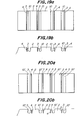
- the stepped zone 3 may be a composite type combining narrow grooves 4 and sipes or narrow cuts 4', such as a middle depressed type 9 shown in Figs. 18(a) and (b), a one side depressed type 10 or 10' as shown in Figs. 19(a) and (b) and Figs. 20(a) and (b), respectively.
- the axial width "w" of the radially innermost side of a stepped portion 3 is greater than that "x" of the radially outermost side thereof.
- the ratio of x/w is preferably in a range from 1.2 to 5.0. The reason is that if the ratio is less than 1.2, the stepped zone 3 cannot sufficiently prevent uneven wear of the land portions for the wear latter period during wearing of the stepped zone 3. On the other hand, if the ratio of x/w is more than 5.0, the axial width "x" of the radially outermost side of the stepped zone is so small that uneven wearing cannot be prevented even in the initial wear stage or that the ground contact area of the entire tread during the initial running stage is so small that wear resistance itself lowers.
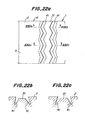
- Figs. 22(a), (b) and (c) illustrate a further modification of the present invention.
- a pair of circumferential grooves 41 are zigzag bent in a land, and a zigzag bent stepped zone 31 is formed between the circumferential grooves 41.
- the circumferential grooves 41 are inclined in the same directions as those of side faces of the stepped zone 31, and the width of the circumferential groove 41 at the deepest portion is made smaller than that at an opening end thereof.
- Figs. 23(a), (b) and (c) show a still further embodiment according to the present invention.
- the tire in this embodiment is the same as that in Figs. 22(a), (b) and (c) except that the distance between circumferential grooves 42 is made greater at the deepest portions than that at opening ends thereof.
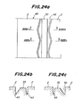
- Figs. 24(a), (b) and (c) illustrate a still further embodiment according to the present invention.
- the illustrated embodiment are formed a pair of circumferential grooves 43 in which far spaced side faces of lands are zigzag bent at the same phase, and their adjacent side faces are made linear.
- a straight stepped zone 33 is formed between these circumferential grooves 43. By so doing, the stepped zone periodically approaches the land portion 2.
- uneven wear can easily and appropriately be prevented during the entire tire use life by the action of the uneven wear-sacrificed portions locally formed on the tread without affecting any adverse affects upon tire performances.
Landscapes
- Engineering & Computer Science (AREA)
- Mechanical Engineering (AREA)
- Tires In General (AREA)
Abstract
Description
- The present invention relates to heavy duty pneumatic tires having excellent uneven wear resistance.
- Recently, radial carcass structure has come to mainly be employed in the case of heavy duty pneumatic tires. When tires of this structure are used in heavy vehicles such as trucks or buses particularly in driving wheels or in driven wheels, so-called uneven wearing often occurs far before the tires do not reach a complete wear life span, thereby causing poor appearance. Further, it is feared that when the tires are continuously used as they are, such a use leads to breakage of land portions called rib punches, thereby causing problems in tire performances.
- In order to reduce uneven wear resistance of treads, there have been many proposals on crown contour configurations and tread patterns, particularly on sipe arrangements. However, appropriate countermeasures for preventing uneven wearing have not been established yet.
- For reference, as typical known literatures, for example, there are available U.S. Patent 4,155,392 in which the crown contour configuration is varied, and U.S. Patent 3,550,665 in which sipes are provided on opposite side portions of each of a ribs.
- Further, as in the case of U.S. Patent 4,200,134, in order to prevent uneven wearing around grooves, a countermeasure is proposed to prevent stress concentration upon projections of land portions arranged corresponding to a zigzag groove by means of a stress-mitigating rib having the same surface level as that of the land portions of the tread while being spaced from the land portions via the groove. However, in such a countermeasure, the stress-mitigating rib itself comes to peel off. Thus, even if occurrence of uneven wearing can be retarded, it cannot ultimately be prevented.
- The above uneven wearing phenomenon occurring in the tires of this type as a matter of course depends upon running conditions, road surface conditions, etc. When tires are run on recently greatly consolidated highway roads exclusively for automobiles over an extended period of time, speed of wearing which changes the contour configuration of the tire varies depending upon external forces (forces inputted to the tire) exerted from the tread in the ground-contacting area of the tire. Under the circumstances, wearing is acceleratingly accumurated and promoted in the area at which the wearing is faster.
- To the contrary, there are conventionally techniques for increasing a ground-contact pressure at a portion at which uneven wearing is more likely to occur or techniques for reducing shearing forces (by notches or the like) so as to control or retard acceleratingly promoted wearing. In such techniques, even if accelerated wearing can be retarded, wearing cannot be prevented from appearing soon. Further, it was often observed that load sharing of the tire varies owing to the wearing, and that uneven wearing occurs.
- The present invention is to propose heavy duty pneumatic tires in which simple and appropriate countermeasures are taken against uneven wearing through fundamentally solving uneven wearing behavior in such tires.
- More particularly, the present invention is based on knowledge obtained by detailed experiments and examinations of movements and directions of forces inputted to tires, and is to establish countermeasures for effectively preventing uneven wearing by locally shutting uneven wearing inevitably occurring on the tread of the tire without adversely influencing tire performances.
- According to the present invention, there is a provision of a heavy duty pneumatic tire preventing uneven wearing, comprising main grooves continuously extending in a tread of the tire along a circumference thereof, land portions separated by the main grooves, and stepped zones each having a surface located radially inside of a contour line of the tread by a step as viewed sectionally, each of said stepped zones being separated from the adjacent land portions via a pair of circumferentially extending grooves or narrow cuts, whereby an uneven wear-sacrificed portion is formed by a surface of each of the stepped zones, said uneven wearing-sacrificing portion slide-contacting with the tread within the tread ground-contacting area for supporting the load exerted upon the tire.
- By so constructing, uneven wearing of the tire can easily and appropriately be prevented during the entire use life due to the action of the uneven wearing-sacrificing portions locally given to the tread without particularly influencing the tire performances.
- These and other objects, features, and advantages of the invention will be appreciated upon reading of the following description of the invention when taken in conjunction with the attached drawings, with the understanding that some modifications, variations and changes of the same could be made by the skilled person in the art to which the invention pertains without departing from the spirit of the invention or the scope of claims appended hereto.
- For a better understanding of the invention, reference is made to the attached drawings, wherein:
- Figs. 1 (a) and (b) are a developed view and a sectional view of a left half principal portion of a heavy duty pneumatic tire embodying the present invention, respectively;
- Fig. 2 is a developed view of a left half principal portion of another heavy duty pneumatic tire according to the present invention;
- Figs. 3(a) and (b) are a developed view and a sectional view of a left half principal portion of a modification of Fig. 2 according to the present invention, respectively;
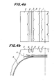
- Figs. 4(a) and (b) are a developed view and a sectional view of a left half principal portion of still another embodiment according to the present invention;
- Figs. 5(a) and (b) are a developed view and a sectional view of a left half principal portion of a further embodiment according to the present invention, respectively;
- Figs. 6 through 9 show still further embodiments according to the present invention;
- Figs. 10(a) and (b) are diagrams showing the relationship between .e'/.e and the tangential shearing forces and the relationship between the load ratio per the normal load W and the tangential shearing forces, respectively;
- Figs. 11 (a) and (b) are a developed view and a sectional view of a left half principal portion of a further embodiment according to the present invention, respectively;
- Figs. 12(a) and (b) are a developed view and a sectional view of a left half principal portion of a prior art tire;
- Fig. 13 illustrates a worn state of a tire tested; and
- Figs. 14 through 24 show still further embodiments according to the present invention.
- In the present invention, the tread pattern includes the main grooves continuously extending circumferentially along the tread as well as circumferential grooves and/or narrow cuts, and is not limited to tires in which the pattern looks like in parallel with the tire equator, so called circumferentially straightly extending grooves. The tread pattern may include well known zigzag grooves. Further, it is needless to say that the land portions separated by the above main grooves include ribs, blocks divided by lateral grooves and/or auxiliary grooves, and rib-block composite patterns including such ribs and blocks.
- The invention will be explained in more detail with reference to the attached drawings. In the drawings, same or similar reference numerals and characters denote same or similar parts.
- In Figs. 1 (a) and (b) are shown a developed view and a sectional view of a left half principal portion of a tread of a heavy duty pneumatic tire according to the present invention.
Reference numerals Reference numerals -
- Fig. 2 is a developed view of another embodiment according to the present invention, in which rows of
cuts 7 are provided in edges of each ofland portions 2 facing main grooves and narrow grooves to reduce shearing forces occurring at groove edges. - Figs. 3(a) and (b) illustrate a further embodiment according to the present invention, in which the number of cuts 7' is reduced as compared with that of the
cuts 7 in Fig. 2, and instead a scoopedportion 8 is formed at each of buttresses of the tire to reduce uneven wearing due to lateral forces exerted upon the tire. Although Figs. 1 through 3 illustrate the tires in which the land is divided into a center rib and an intermediate rib by thenarrow grooves 4 which define thestepped zone 3, Figs. 4(a) and (b) do an embodiment in which a land is divided into a side rib and an intermediate rib. - Figs. 5(a) and (b) illustrate an embodiment having a center main groove 1'. Instead of the
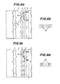
narrow grooves 4 in Fig. 1, astepped zone 3 is spaced from theland portions 2 by sipes 4' (narrow cuts). - Figs. 6(a) and (c) are developed views of still further embodiments according to the present invention, and Figs. 6(b) and (d) are sectional views of Figs. 6(a) and (c) along lines Vlb-Vlb and Vld-Vld, respectively. In Figs. 6(a) and (b), the
stepped zone 3 in Figs. 3(a) and (b) are divided bylateral sipes 8 in the tire circumferential direction. In Figs. 6(c) and (d), thestepped zone 3 of Figs. 3(a) and (b) is similarly divided by lateral grooves 8'. Thereby, shearing forces at thestepped zone 3 itself are reduced. - In Figs. 7(a) and (b) are shown developed views of a tire of Fig. 5 to which the countermeasure in Figs. 6(a) and (b) or that in Figs. 6(c) and (d) is applied, respectively.
- Next, functions of the above-mentioned embodiments according to the present invention will be explained.
- In general, when a tire rotates under application of a load, a tread is sheared in a tangential direction so that a shearing force occurs on the tread in the tangential direction. Fig. 8(a) shows the distribution of shearing forces at
land portions 2 of the tread in the tire axial direction. Solid lines denote the distribution of shearing forces in a conventional tire sectionally shown in Fig. 8(b). Broken lines denote the distribution of shearing forces in the case of a tire according to the present invention in Fig. 8(c) provided with stepped zones 3 (A lowered surface level "8" of each of the stepped zones is set at 2 mm). In Fig. 8(a), shearing forces on a driving side and on a braking side are given on positive and negative zones of the ordinate, respectively. - It was experimentally confirmed that uneven wearing mainly occurs on the negative shearing force zone of the tire, and that uneven wearing is likely to occur from a location of the tire at which the shearing force in the tangential direction is greater on the negative zone within the tread surface.
- As is clearly seen from comparison in the distribution of the shearing forces between the solid lines and the broken lines in Fig. 8(a), the shearing forces on the land portions of the tire according to the present invention having the stepped zones shift toward the positive zone than those in the conventional tire.
- That is, it is made clear that the
stepped zones 3 serve as uneven wear-sacrificed portions for undergoing uneven wear which should have occurred on theland portions 2 of the tread. - In order to exhibit the above effect, the
stepped zones 3 must contact with the ground so that uneven wear may not occur on theland portions 2. Further, the stepped zones must be radially stepped down by such a level that sufficient negative shearing forces may occur to make the stepped zones serve as the uneven wear-sacrificed portions. - Therefore, it is indispensable that the surfaces of the stepped zones contact with the ground within a ground-contacting area of the tread to support a load applied to the tire.
- In order to effectively produce negative shearing forces at the stepped
zones 3, it is preferable to set the ratio of ℓ'/ℓ [see foot prints of the tire treads in Figs. 9(a) and (b)] at less than 0.95 in which and ℓ' are the shorter one of circumferential ground contact lengths of theland potions 2 adjacent to the steppedzone 3, and the ground contact length of the steppedzone 3, respectively, when 200% of a normal load is applied to the tire. If the ratio of ℓ'/ℓ is less than 0.95, as shown in Fig. 10(a), the shearing forces occurring on the steppedzone 3 in the tangential direction rapidly increases in the negative direction, and the effect of the ratio of ℓ'/ℓ affecting uneven wear-sacrificed function at the steppedzone 3 increases as the ratio of ℓ'/ℓ becomes smaller. - Further, the lowered surface level "6" of the stepped zone 3 [see Fig. 1 (b), and Fig. 5(b)] is preferably set at such a value that the stepped
zone 3 may contact the ground under application of 500/0 to 2000/0 of the maximum load to the tire. [The maximum loads are specified for tires of various kinds. For example, see TRA (Tire and Rim Association, "Tire load limit", JATOMA (Japan Automobile Tire Organization Manufacturer Association), "Tire Maximum Loads" etc.] - Fig. 10(b) shows tangential shearing forces at the stepped zone having a lowered surface level limit under each of specified loading percentages. The lowered surface level limit is to bring the stepped zone into contact with the ground under the specified loading percentage. As is clear from Fig. 10(b), if the lowered surface level is so small that the stepped zones contact the ground under application of less than 50% of the maximum load, sufficient negative shearing forces cannot be obtained, while if the lowered surface level is so great that the stepped zones begin to contact the ground under application of more than 200% of the maximum load, the stepped zone will not contact the ground during practical use of the tire so that effective shearing forces cannot be obtained. In Fig. 10(b) are plotted tangential shearing forces via loading percentages with respect to a tire having a tread with a tread gauge h = 20 mm and elasticity E of a tread rubber being 53 kg/cm2. An actual tread contact area S of the tire was varied among So.s:143 cm2, So.5:191 cm2, Si.o:318 cm2, Si.5:398 cm2, S2.o:445 cm2 and S2.3:461 cm2 by variously changing the loading percentage of the normal load W (2,700 kg) upon the tread. The suffix to S denotes the loading times of the maximum load.
- According to Fig. 1 (b), lower and upper limits of the lowered surface level "8" with respect to the sectional contour line of the tread are determined by the following formulae, respectively.

- In order to sufficiently produce the negative shearing forces at the stepped zones, the
land portions 2 must not hinder the tangential shearing of the steppedzones 3. It is desired that the stepped zones will not contact the land portions when the former are sheared. - Next, if the total width of the stepped
zones 3 in the tire axial direction is less than 5% of the ground contacting width of the tread, no sufficient effect cannot be obtained, while if it is more than 250/o of the tread ground contacting width, wear resistance is conspicuously lowered to the contrary. Thus, the total width of the stepped zones is preferably in a range from 5 to 25% of the tread ground contacting width. - If the actually ground contacting area of the whole stepped
zones 3 exceeds 200/0 of that of the whole land portions, wear resistance is conspicuously lowered. Thus, the actually ground contacting area of the whole steppedzones 3 is preferably not more than 20% of that of the whole land portions. - Furthermore, in order to effectively produce the negative shearing forces at the stepped
zones 3, the deformation of the stepped zones must be not flexural deformation, but shearing. For this purpose, it is necessary to increase the rigidity of the stepped zones in the rotating direction. Since there is the limitation that if the stepped zone is made wider, wear resistance lowers, it is necessary that the rigidity of the stepped zone is made greater in the tangential direction by making the ground contact length ℓ' larger than the axial width "w" of the steppedzone 3. Sufficient effects can be obtained when the axial width "w" of the steppedzone 3 is not more than 1/2 of the axial width "b" of theland portion 2 adjacent thereto on each of the opposite sides thereof. - Next, specific examples are given in illustration of the present invention below.
- First, Reference Examples 1 and 2 which were the same as the tires illustrated in Figs. 12 and 1, respectively, except for the following were prepared. In Reference Example 1, no anti-wearing countermeasure was taken, while in Reference Example 2, the lowered surface level of the stepped zones was set at zero. On the other hand, tires each having a tread pattern shown in Fig. 1,2,3 or 4 with a lowered surface level "8" and a width "W" specified in the following Table 1 were separately prepared. All the tires had a tire size of 10.00 R 20. With respect to the above tires, the width and depth of uneven wearing were compared, and results are shown in Table 1.
- In tests, each of the tires was fitted to a front wheel of a 2 wheel-driven
type 4 wheel vehicle, and run completely over a running distance of 80,000 km. Comparison was made by taking the total width of broken portions occurring at edges of land portions at ① through ⑤ of a left half portion of the tire as shown in Fig. 13 as an uneven worn width, while the average depth of the broken portions at the portions ① through ⑤ being taken as the depth of the uneven wear.
- Test tires each having a tire size of 10.00 R 20 and a tread pattern shown in Fig. 4,11 or 12 were prepared. In Reference Example 3, the lowered surface level "5" was set at 0 mm, and in Reference Example 4, no anti-wearing countermeasure was taken as shown in Figs. 12(a) and (b). Various dimensions of these tires are given in the following Table 2.


- Each of the tires was fitted to a front wheel of a 2-wheel driven
type 4 wheel vehicle, and run completely over a running distance of 80,000 km under application of a normal load. - After the running over 80,000 km, with respect to each tire, the magnitude of uneven wearing at the land portions through was measured in the manner shown in Fig. 13, and comparisons were made with respect to the total width and the average depth of the uneven worn portions. Evaluation results are shown in Table 3.
- As is clear from the results in Table 3, uneven wear-sacrificed portions according to the present invention function to conspicuously reduce or effectively prevent uneven wearing accumulating during an almost entire wearing life of the tire.
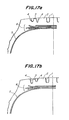
- Similar tests were carried out with respect to a tire having zigzag main grooves 1 as shown in Figs. 14(a) and (b), a tire having
lateral grooves 7 added as shown in Figs. 15(a) and (b), a tire having shoulders rounded as shown in Figs. 16(a) and (b), and a tire shown in Figs. 17(a) and (b) in which depths ofnarrow grooves 4 sandwiching a steppedzone 3 are varied. Consequently, results similar to those of the tire shown in Fig. 1 were obtained. - In addition to a platform shape occupying inside a wide main groove as illustrated in the above explanation and the attached drawings, the stepped
zone 3 may be a composite type combiningnarrow grooves 4 and sipes or narrow cuts 4', such as a middledepressed type 9 shown in Figs. 18(a) and (b), a one side depressedtype 10 or 10' as shown in Figs. 19(a) and (b) and Figs. 20(a) and (b), respectively. - Further, wearing is more conspicuously accumulated and promoted in pneumatic tires in a stage from a wearing middle period to a wearing latter period after running over a long distance as compared with a wearing initial stage. Therefore, if the axial width of the stepped zone is constant in a tire radial direction, wearing of land portions in the stage from wearing middle period to the wearing latter period exceeds wear-preventing ability of the stepped zones. In some cases, uneven wear of the land portions cannot assuredly be prevented. Thus, it is preferable that while the radially outer face of each of the stepped zones is located radially inside the sectional contour line of the tread, the axial width of the radially inner side of each of the stepped zones is greater than that of the radially outer side thereof.
- For instance, as shown in Fig. 21, the axial width "w" of the radially innermost side of a stepped
portion 3 is greater than that "x" of the radially outermost side thereof. The ratio of x/w is preferably in a range from 1.2 to 5.0. The reason is that if the ratio is less than 1.2, the steppedzone 3 cannot sufficiently prevent uneven wear of the land portions for the wear latter period during wearing of the steppedzone 3. On the other hand, if the ratio of x/w is more than 5.0, the axial width "x" of the radially outermost side of the stepped zone is so small that uneven wearing cannot be prevented even in the initial wear stage or that the ground contact area of the entire tread during the initial running stage is so small that wear resistance itself lowers. - Figs. 22(a), (b) and (c) illustrate a further modification of the present invention. In this embodiment, a pair of
circumferential grooves 41 are zigzag bent in a land, and a zigzag bent steppedzone 31 is formed between thecircumferential grooves 41. By so constructing, when the width of the steppedzone 31 is the same, the ground contact area becomes greater than in the case of a stepped zone of a straight rib shape, so that uneven wear can more effectively be reduced. Further, in this embodiment, thecircumferential grooves 41 are inclined in the same directions as those of side faces of the steppedzone 31, and the width of thecircumferential groove 41 at the deepest portion is made smaller than that at an opening end thereof. - Figs. 23(a), (b) and (c) show a still further embodiment according to the present invention. The tire in this embodiment is the same as that in Figs. 22(a), (b) and (c) except that the distance between
circumferential grooves 42 is made greater at the deepest portions than that at opening ends thereof. - Figs. 24(a), (b) and (c) illustrate a still further embodiment according to the present invention. In the illustrated embodiment are formed a pair of
circumferential grooves 43 in which far spaced side faces of lands are zigzag bent at the same phase, and their adjacent side faces are made linear. A straight steppedzone 33 is formed between thesecircumferential grooves 43. By so doing, the stepped zone periodically approaches theland portion 2. - As mentioned above, according to the present invention, uneven wear can easily and appropriately be prevented during the entire tire use life by the action of the uneven wear-sacrificed portions locally formed on the tread without affecting any adverse affects upon tire performances.
Claims (9)

in which:
Applications Claiming Priority (4)
| Application Number | Priority Date | Filing Date | Title |
|---|---|---|---|
| JP26601187 | 1987-10-20 | ||
| JP266011/87 | 1987-10-20 | ||
| JP26524887 | 1987-10-22 | ||
| JP265248/87 | 1987-10-22 |
Publications (3)
| Publication Number | Publication Date |
|---|---|
| EP0313361A2 true EP0313361A2 (en) | 1989-04-26 |
| EP0313361A3 EP0313361A3 (en) | 1990-01-10 |
| EP0313361B1 EP0313361B1 (en) | 1993-07-21 |
Family
ID=26546886
Family Applications (1)
| Application Number | Title | Priority Date | Filing Date |
|---|---|---|---|
| EP88309881A Expired - Lifetime EP0313361B1 (en) | 1987-10-20 | 1988-10-20 | Heavy duty pneumatic tires preventing uneven wearing |
Country Status (8)
| Country | Link |
|---|---|
| US (2) | US5131444A (en) |
| EP (1) | EP0313361B1 (en) |
| KR (1) | KR950008772B1 (en) |
| AU (1) | AU594000B2 (en) |
| BR (1) | BR8805397A (en) |
| CA (1) | CA1329356C (en) |
| DE (1) | DE3882483T2 (en) |
| ES (1) | ES2043841T3 (en) |
Cited By (10)
| Publication number | Priority date | Publication date | Assignee | Title |
|---|---|---|---|---|
| AT393247B (en) * | 1989-05-10 | 1991-09-10 | Semperit Ag | RADIAL TIRES FOR TRUCKS |
| US5180453A (en) * | 1989-03-24 | 1993-01-19 | Bridgestone Corporation | Heavy duty pneumatic tires |
| US5345988A (en) * | 1992-05-27 | 1994-09-13 | The Yokohama Rubber Co., Ltd. | Pneumatic radial tire for heavy loads |
| EP0659594A1 (en) * | 1993-12-27 | 1995-06-28 | Sumitomo Rubber Industries Limited | Pneumatic tyre for heavy load |
| EP0787602A1 (en) * | 1996-02-02 | 1997-08-06 | Bridgestone Corporation | Pneumatic radial tire |
| EP0816131A1 (en) * | 1996-07-04 | 1998-01-07 | Sumitomo Rubber Industries Limited | Heavy duty pneumatic tyre |
| US5720831A (en) * | 1989-10-23 | 1998-02-24 | Bridgestone Corporation | Tread of heavy duty pneumatic radial tire |
| EP2143572A1 (en) | 2008-07-09 | 2010-01-13 | Continental Reifen Deutschland GmbH | Pneumatic tyres for a vehicle |
| CN101311008B (en) * | 2007-05-23 | 2012-06-13 | 住友橡胶工业株式会社 | Tyre for heavy load |
| WO2019115036A1 (en) * | 2017-12-11 | 2019-06-20 | Continental Reifen Deutschland Gmbh | Utility vehicle tyre |
Families Citing this family (26)
| Publication number | Priority date | Publication date | Assignee | Title |
|---|---|---|---|---|
| US5247999A (en) * | 1991-09-25 | 1993-09-28 | Fowler John T | Oil wellhead fire extinguishing apparatus having adjustable support feet and labyrinth module |
| JP2905704B2 (en) * | 1994-09-28 | 1999-06-14 | 住友ゴム工業株式会社 | Heavy duty pneumatic tires |
| US5833780A (en) * | 1995-06-21 | 1998-11-10 | The Yokohama Rubber Co., Ltd. | Pneumatic radial tire for heavy loads |
| USD399460S (en) | 1997-06-02 | 1998-10-13 | The Goodyear Tire & Rubber Company | Tire tread |
| USD402238S (en) | 1997-10-15 | 1998-12-08 | The Goodyear Tire & Rubber Company | Tire tread |
| US7267148B2 (en) * | 1999-08-10 | 2007-09-11 | Michelin Recherche Et Technique S.A. | Measurement of adherence between a vehicle wheel and the roadway |
| JP4577929B2 (en) * | 1999-10-26 | 2010-11-10 | 株式会社ブリヂストン | Pneumatic tire |
| JP2002002223A (en) * | 2000-06-21 | 2002-01-08 | Yokohama Rubber Co Ltd:The | Pneumatic tire |
| US6631746B2 (en) | 2001-04-25 | 2003-10-14 | Bridgestone/Firestone North American Tire, Llc | Undercut tie bar for pneumatic tire |
| US6695024B2 (en) | 2001-08-03 | 2004-02-24 | Bridgestone/Firestone North American Tire, Llc | Pneumatic tire having tapered tie bars |
| US7090735B2 (en) | 2001-08-06 | 2006-08-15 | Bridgestone/Firestone North American Tire, Llc | Method of compensating for residual aligning torque (RAT) |
| US20040060628A1 (en) * | 2002-09-30 | 2004-04-01 | Grimm John H.W. | Heavy duty pneumatic tire |
| WO2005058617A1 (en) * | 2003-12-16 | 2005-06-30 | Bridgestone Corporation | Pneumatic tire for heavy load |
| DE602005020621D1 (en) * | 2004-06-23 | 2010-05-27 | Bridgestone Corp | TIRE |
| US7360568B2 (en) * | 2005-01-27 | 2008-04-22 | Bridgestone Firestone North American Tire, Llc | Tire having narrowing sipes |
| US20070068613A1 (en) * | 2005-09-28 | 2007-03-29 | Bridgestone Firestone North American Tire, Llc | Band for use on a tire |
| JP4866177B2 (en) * | 2006-08-28 | 2012-02-01 | 住友ゴム工業株式会社 | Heavy duty tire |
| EP2444257B1 (en) * | 2009-06-15 | 2017-01-04 | Bridgestone Corporation | Heavy duty tire |
| DE102009026384A1 (en) * | 2009-08-17 | 2011-02-24 | Continental Reifen Deutschland Gmbh | Vehicle tires |
| JP5099203B2 (en) * | 2010-10-04 | 2012-12-19 | 横浜ゴム株式会社 | Pneumatic tire |
| DE102011050712A1 (en) * | 2011-05-30 | 2012-12-06 | Continental Reifen Deutschland Gmbh | Tread pattern of a pneumatic vehicle tire for commercial vehicles |
| US8689843B2 (en) | 2011-12-14 | 2014-04-08 | Bridgestone Americas Tire Operations, Llc | Snow performance peaks |
| MX2015005332A (en) * | 2012-10-31 | 2015-07-23 | Michelin & Cie | Tire tread with improved tread element edge. |
| JP2017501082A (en) | 2013-12-26 | 2017-01-12 | ブリヂストン アメリカズ タイヤ オペレーションズ、 エルエルシー | Tire tread with flexible gate device |
| USD788025S1 (en) | 2016-03-02 | 2017-05-30 | Bridgestone Americas Tire Operations, Llc | Tire tread |
| DE102022213922A1 (en) | 2022-12-19 | 2024-06-20 | Continental Reifen Deutschland Gmbh | Commercial vehicle tires |
Family Cites Families (19)
| Publication number | Priority date | Publication date | Assignee | Title |
|---|---|---|---|---|
| BE384271A (en) * | 1930-11-20 | |||
| US2197662A (en) * | 1937-05-17 | 1940-04-16 | Hannah Lorig | Tire of the type adapted to be used on automobiles and various vehicles |
| US2260193A (en) * | 1938-07-25 | 1941-10-21 | M C O Corp | Nonskid tire |
| NL76758C (en) * | 1950-12-07 | |||
| GB903389A (en) * | 1957-09-30 | 1962-08-15 | Pirelli | Improvements in or relating to pneumatic tyres |
| NL243647A (en) * | 1958-09-23 | |||
| NL133932C (en) * | 1967-09-18 | |||
| FR2119263A5 (en) * | 1970-12-24 | 1972-08-04 | Michelin & Cie | |
| FR2128232B1 (en) * | 1971-03-12 | 1973-12-07 | Uniroyal | |
| FR2317112A1 (en) * | 1975-07-07 | 1977-02-04 | Michelin & Cie | Tyre tread with sloping tread crowns - to reduce peel damage due to local compression |
| JPS53128807A (en) * | 1977-04-18 | 1978-11-10 | Bridgestone Corp | Radial pneumatic tire for heavy loading |
| GB2018208B (en) * | 1978-04-08 | 1982-08-18 | Bridgestone Tire Co Ltd | Pneumatic radial tyre for heyvy vehicles |
| US4353402A (en) * | 1978-06-16 | 1982-10-12 | Bandag Incorporated | Slitted tire tread |
| JPS5522534A (en) * | 1978-08-04 | 1980-02-18 | Bridgestone Corp | Aircraft pneumatic tire having high durability |
| JPS5555005A (en) * | 1978-10-17 | 1980-04-22 | Bridgestone Corp | Radial tire for heavy vehicle restrained in wandering phenomenon |
| IT1101233B (en) * | 1978-12-22 | 1985-09-28 | Pirelli | TREAD DESIGN WITH SIDE GROOVES |
| US4480671A (en) * | 1982-04-26 | 1984-11-06 | Michelin Recherche Et Technique S.A. | Tread and heavy duty tire |
| DE3314775A1 (en) * | 1983-04-23 | 1984-10-25 | Continental Gummi-Werke Ag, 3000 Hannover | VEHICLE TIRES |
| US4936363A (en) * | 1988-08-15 | 1990-06-26 | The Goodyear Tire & Rubber Company | Tread for a pneumatic tire with circumferential slot to prevent the spread of river wear |
-
1988
- 1988-10-14 US US07/257,896 patent/US5131444A/en not_active Expired - Lifetime
- 1988-10-18 AU AU24013/88A patent/AU594000B2/en not_active Expired
- 1988-10-19 BR BR8805397A patent/BR8805397A/en not_active IP Right Cessation
- 1988-10-19 CA CA000580644A patent/CA1329356C/en not_active Expired - Lifetime
- 1988-10-20 DE DE88309881T patent/DE3882483T2/en not_active Expired - Lifetime
- 1988-10-20 KR KR1019880013710A patent/KR950008772B1/en not_active Expired - Lifetime
- 1988-10-20 ES ES88309881T patent/ES2043841T3/en not_active Expired - Lifetime
- 1988-10-20 EP EP88309881A patent/EP0313361B1/en not_active Expired - Lifetime
-
1993
- 1993-10-19 US US08/137,757 patent/US5445201A/en not_active Expired - Lifetime
Cited By (16)
| Publication number | Priority date | Publication date | Assignee | Title |
|---|---|---|---|---|
| US5180453A (en) * | 1989-03-24 | 1993-01-19 | Bridgestone Corporation | Heavy duty pneumatic tires |
| AT393247B (en) * | 1989-05-10 | 1991-09-10 | Semperit Ag | RADIAL TIRES FOR TRUCKS |
| US5720831A (en) * | 1989-10-23 | 1998-02-24 | Bridgestone Corporation | Tread of heavy duty pneumatic radial tire |
| US5345988A (en) * | 1992-05-27 | 1994-09-13 | The Yokohama Rubber Co., Ltd. | Pneumatic radial tire for heavy loads |
| US5753058A (en) * | 1993-12-27 | 1998-05-19 | Sumitomo Rubber Industries, Ltd. | Pneumatic tire for heavy load |
| EP0659594A1 (en) * | 1993-12-27 | 1995-06-28 | Sumitomo Rubber Industries Limited | Pneumatic tyre for heavy load |
| US5833781A (en) * | 1993-12-27 | 1998-11-10 | Sumitomo Rubber Industries, Ltd. | Pneumatic tire for heavy load |
| EP0787602A1 (en) * | 1996-02-02 | 1997-08-06 | Bridgestone Corporation | Pneumatic radial tire |
| US6006804A (en) * | 1996-02-02 | 1999-12-28 | Bridgestone Corporation | Pneumatic radial tire including vibration buffer wall |
| EP0816131A1 (en) * | 1996-07-04 | 1998-01-07 | Sumitomo Rubber Industries Limited | Heavy duty pneumatic tyre |
| US6112787A (en) * | 1996-07-04 | 2000-09-05 | Sumito Rubber Industries, Ltd. | Heavy duty pneumatic tire including narrow rib |
| CN101311008B (en) * | 2007-05-23 | 2012-06-13 | 住友橡胶工业株式会社 | Tyre for heavy load |
| EP2143572A1 (en) | 2008-07-09 | 2010-01-13 | Continental Reifen Deutschland GmbH | Pneumatic tyres for a vehicle |
| WO2019115036A1 (en) * | 2017-12-11 | 2019-06-20 | Continental Reifen Deutschland Gmbh | Utility vehicle tyre |
| CN111479706A (en) * | 2017-12-11 | 2020-07-31 | 大陆轮胎德国有限公司 | Utility Vehicle Tires |
| US11964512B2 (en) | 2017-12-11 | 2024-04-23 | Continental Reifen Deutschland Gmbh | Utility vehicle tire |
Also Published As
| Publication number | Publication date |
|---|---|
| BR8805397A (en) | 1989-06-20 |
| US5445201A (en) | 1995-08-29 |
| CA1329356C (en) | 1994-05-10 |
| EP0313361B1 (en) | 1993-07-21 |
| KR890006420A (en) | 1989-06-13 |
| DE3882483T2 (en) | 1993-12-09 |
| AU594000B2 (en) | 1990-02-22 |
| KR950008772B1 (en) | 1995-08-08 |
| ES2043841T3 (en) | 1994-01-01 |
| US5131444A (en) | 1992-07-21 |
| DE3882483D1 (en) | 1993-08-26 |
| EP0313361A3 (en) | 1990-01-10 |
| AU2401388A (en) | 1989-05-11 |
Similar Documents
| Publication | Publication Date | Title |
|---|---|---|
| EP0313361A2 (en) | Heavy duty pneumatic tires preventing uneven wearing | |
| EP0205233B1 (en) | Pneumatic tyre | |
| US5361815A (en) | Tread for a tire with blocks and ribs | |
| EP0841199B1 (en) | Pneumatic tyre | |
| CA1194770A (en) | Heavy duty pneumatic tires | |
| US6000450A (en) | Studless tire | |
| US3286756A (en) | Automobile tire | |
| US4724878A (en) | Heavy-duty pneumatic radial tire tread with narrow groove near shoulder | |
| KR0145071B1 (en) | Sole for a heavy duty tyre having central ribs provided with inclined incisions | |
| JP3533757B2 (en) | Pneumatic tire | |
| US5022448A (en) | Pneumatic tire including lateral tread grooves with a bridge thereacross | |
| CA1334373C (en) | Radial tire for heavy duty vehicles | |
| JPS626802A (en) | Pneumatic tire excellent in wettability | |
| JPH05178015A (en) | Pneumatic radial tire for heavy load | |
| JPH0253611A (en) | Pneumatic heavy-load radial tire | |
| JPH0288311A (en) | Pneumatic tire | |
| JPH0872508A (en) | Pneumatic tire for heavy load | |
| JP2698396B2 (en) | Pneumatic tires for trucks and buses | |
| JP2744612B2 (en) | Pneumatic tires for heavy loads that prevent uneven wear | |
| CA1313116C (en) | Pneumatic radial tire for heavy-duty vehicles | |
| JPH08118918A (en) | Pneumatic radial tire | |
| FI103334B (en) | Figure knob ring | |
| JPH02179506A (en) | Pneumatic tire | |
| JP2754228B2 (en) | Pneumatic tire | |
| JP2890020B2 (en) | Pneumatic tire |
Legal Events
| Date | Code | Title | Description |
|---|---|---|---|
| PUAI | Public reference made under article 153(3) epc to a published international application that has entered the european phase |
Free format text: ORIGINAL CODE: 0009012 |
|
| AK | Designated contracting states |
Kind code of ref document: A2 Designated state(s): BE DE ES FR GB IT LU NL |
|
| PUAL | Search report despatched |
Free format text: ORIGINAL CODE: 0009013 |
|
| AK | Designated contracting states |
Kind code of ref document: A3 Designated state(s): BE DE ES FR GB IT LU NL |
|
| 17P | Request for examination filed |
Effective date: 19900615 |
|
| 17Q | First examination report despatched |
Effective date: 19920309 |
|
| GRAA | (expected) grant |
Free format text: ORIGINAL CODE: 0009210 |
|
| AK | Designated contracting states |
Kind code of ref document: B1 Designated state(s): BE DE ES FR GB IT LU NL |
|
| ITF | It: translation for a ep patent filed | ||
| REF | Corresponds to: |
Ref document number: 3882483 Country of ref document: DE Date of ref document: 19930826 |
|
| ET | Fr: translation filed | ||
| EPTA | Lu: last paid annual fee | ||
| REG | Reference to a national code |
Ref country code: ES Ref legal event code: FG2A Ref document number: 2043841 Country of ref document: ES Kind code of ref document: T3 |
|
| PLBE | No opposition filed within time limit |
Free format text: ORIGINAL CODE: 0009261 |
|
| 26N | No opposition filed | ||
| REG | Reference to a national code |
Ref country code: GB Ref legal event code: IF02 |
|
| PGFP | Annual fee paid to national office [announced via postgrant information from national office to epo] |
Ref country code: DE Payment date: 20071018 Year of fee payment: 20 Ref country code: NL Payment date: 20071015 Year of fee payment: 20 Ref country code: LU Payment date: 20071025 Year of fee payment: 20 Ref country code: ES Payment date: 20071102 Year of fee payment: 20 |
|
| PGFP | Annual fee paid to national office [announced via postgrant information from national office to epo] |
Ref country code: IT Payment date: 20071026 Year of fee payment: 20 |
|
| PGFP | Annual fee paid to national office [announced via postgrant information from national office to epo] |
Ref country code: BE Payment date: 20071220 Year of fee payment: 20 |
|
| PGFP | Annual fee paid to national office [announced via postgrant information from national office to epo] |
Ref country code: FR Payment date: 20071009 Year of fee payment: 20 Ref country code: GB Payment date: 20071017 Year of fee payment: 20 |
|
| BE20 | Be: patent expired |
Owner name: *BRIDGESTONE CORP. Effective date: 20081020 |
|
| REG | Reference to a national code |
Ref country code: GB Ref legal event code: PE20 Expiry date: 20081019 |
|
| PG25 | Lapsed in a contracting state [announced via postgrant information from national office to epo] |
Ref country code: NL Free format text: LAPSE BECAUSE OF EXPIRATION OF PROTECTION Effective date: 20081020 |
|
| NLV7 | Nl: ceased due to reaching the maximum lifetime of a patent |
Effective date: 20081020 |
|
| REG | Reference to a national code |
Ref country code: ES Ref legal event code: FD2A Effective date: 20081021 |
|
| PG25 | Lapsed in a contracting state [announced via postgrant information from national office to epo] |
Ref country code: ES Free format text: LAPSE BECAUSE OF EXPIRATION OF PROTECTION Effective date: 20081021 |
|
| PG25 | Lapsed in a contracting state [announced via postgrant information from national office to epo] |
Ref country code: GB Free format text: LAPSE BECAUSE OF EXPIRATION OF PROTECTION Effective date: 20081019 |