EP0313246A2 - Richtungsgebung eines Gegenstandes - Google Patents
Richtungsgebung eines Gegenstandes Download PDFInfo
- Publication number
- EP0313246A2 EP0313246A2 EP19880309449 EP88309449A EP0313246A2 EP 0313246 A2 EP0313246 A2 EP 0313246A2 EP 19880309449 EP19880309449 EP 19880309449 EP 88309449 A EP88309449 A EP 88309449A EP 0313246 A2 EP0313246 A2 EP 0313246A2
- Authority
- EP
- European Patent Office
- Prior art keywords
- article
- detectors
- projectile
- orientation
- article according
- Prior art date
- Legal status (The legal status is an assumption and is not a legal conclusion. Google has not performed a legal analysis and makes no representation as to the accuracy of the status listed.)
- Withdrawn
Links
Images

Classifications
-
- F—MECHANICAL ENGINEERING; LIGHTING; HEATING; WEAPONS; BLASTING
- F41—WEAPONS
- F41G—WEAPON SIGHTS; AIMING
- F41G7/00—Direction control systems for self-propelled missiles
- F41G7/20—Direction control systems for self-propelled missiles based on continuous observation of target position
- F41G7/24—Beam riding guidance systems
- F41G7/26—Optical guidance systems
- F41G7/266—Optical guidance systems for spin-stabilized missiles
-
- F—MECHANICAL ENGINEERING; LIGHTING; HEATING; WEAPONS; BLASTING
- F41—WEAPONS
- F41G—WEAPON SIGHTS; AIMING
- F41G7/00—Direction control systems for self-propelled missiles
- F41G7/20—Direction control systems for self-propelled missiles based on continuous observation of target position
- F41G7/30—Command link guidance systems
- F41G7/301—Details
- F41G7/305—Details for spin-stabilized missiles
Definitions
- the present invention relates to determining the orientation of an article and relates particularly, but not exclusively, to determining the roll orientation of an article which rolls during flight.
- the present invention aims to solve the problem of providing an unambiguous vertical reference for an article which rolls during flight, such as a guided projectile.
- an article comprising at least three detectors for detecting a beam of electromagnetic radiation swept across the article wherein the detectors are so positioned as to enable calculation of the orientation of the article solely from the beam transit times between the detectors.
- the article comprises a plurality of detectors which are offset from a central axis of the article.
- the detectors are all positioned at the same radial distance from the central axis of the article. In that embodiment, the detectors are equiangularly spaced around the central axis of the article. Thus in the case of three detectors, the detectors are equiangularly spaced at 120°.
- the article comprises means for calculating its roll orientation.
- the invention may be applicable in a projectile housing electronics for utilising signals derived from the detectors to calculate roll orientation.
- calculation of roll orientation may be carried out remotely using signals from the detectors.
- the article may comprise means for sensing the order in which the beam impinges on the detectors. This is one way of overcoming a possible 180° ambiguity in the roll orientation calculated using signals from three detectors.
- a system for determining the orientation of an article as defined above comprising means for sweeping a beam of electromagnetic radiation across the article and means for calculating the orientation solely from the beam transit times between the detectors.
- the system comprises means for evaluating the order in which the beam impinges on the detectors.
- the system may comprise means for scanning a beam of electromagnetic radiation so as to define an information field.
- UK Patent No. 2133652B describes apparatus for generating a laser information field for guiding a projectile.
- a laser information field can be generated by scanning a laser beam, first horizontally and then vertically, over an angular segment of the sky.
- the horizontal scanning may take the form of scanning the beam along a horizontal line and then dropping the beam slightly and carrying out a return scan at the same speed to just below where the first scan commenced, dropping the beam again and scanning across and so on.
- the vertical scan may be carried out in the same manner.
- a projectile flying in the laser information field derives information regarding its position in the laser information field from the time which elapses between glimpses of the horizontally and vertically scanning laser beams as is fully explained in UK Patent No. 2133652B.
- the present invention may be implemented by supplementing a laser information field detector by two further detectors so that all three detectors are positioned at a fixed radius from the flight axis of the projectile.
- the laser information field detector may be positioned on the flight axis and three detectors located around it. Referencing is likely to take place at ranges of 1Km or more when the angle subtended by the projectile will be small. Therefore, the rate of angular scan of the laser is desirably adjusted from that of a standard laser information field scan by appropriate adaptation of the control electronics of the laser information field deflector which may be an acousto-optic deflector.
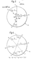
- a projectile is indicated at 10 and the flight axis is indicated at A.
- the projectile 10 may, for example, be a course corrected shell provided with fins (not shown) for implementing course corrections during flight.
- Three equiangularly spaced detectors 11, 12 and 13 are all positioned at a distance R from the flight axis A.
- the distance of each detector 11, 12 and 13 from the vertical axis V intersecting the flight axis A is designated r1, r2 and r3.
- a fourth detector 14 is positioned on the flight axis A and this is a laser information field detector.
- the detectors 11 to 14 are photodiodes having a suitable spectral response and have a fast response time - in the order of nano-seconds.
- a lens 15 is associated with each of the detectors so as to increase the light gathering area for that detector and there is an optical filter 16 aligned with the detector for filtering out background radiation.
- the projectile 10 rolls and it is important to know the roll orientation of the projectile when implementing course corrections.
- the laser information field generating apparatus can be used to implement the present invention.
- each detector, 11, 12 and 13, relative to the vertical axis may be described in terms of the angles ⁇ , ⁇ , ⁇ , and the distances r1, r2 and r3 as shown in Figure 1.
- Simple trigonometry gives the following set of relationships:
- the equiangular spacing of the detectors 11, 12 and 13 means that angles ⁇ , ⁇ and ⁇ are inter-related so that:
- the transit time t of the laser beam across a given distance ⁇ r on the projectile will be related to the projectile range D and the rate of angular scan as follows: where a is a function of angular scan rate and range.
- the ratio of separate time intervals can be used to give:
- the angle ⁇ and hence the roll orientation of the projectile, can be deduced by measuring the transit time of the scanned beam as it passes from one detector to another.
- the accuracy with which angle can be measured depends on the accuracy with which the times at which the detectors glimpse the laser beam can be measured.
- any errors are more critical and it may be advantageous to scan the beam a second or even third time across the projectile at a suitable time interval, e.g. 1 millisecond.
- Equation (3) indicates that the shorter the range the greater the pulse separation so that a measurement at short range will be more accurate than a longer range measurement. Therefore, one possibility is to use the present invention to calibrate a gyroscope on board a projectile so that the gyroscope can provide roll orientation information from a particular range onwards.
- the scanning rate of the laser beam will be in the order of one millisecond per sweep. Therefore the time taken for the beam to cross the projectile is likely to be in the order of microseconds.
- the roll rate of a course corrected projectile is not likely to exceed 1Khz.
- the laser information field detector may be positioned centrally and be supplemented by three circumferentially spaced roll reference detectors.
- a laser projector which simply sweeps a laser beam across the path of a projectile at predetermined time intervals may be all that is needed.
- other than laser beams e.g. light beams, radar beams or other electromagnetic radiation.
- the invention is not limited in its application to course corrected projectiles but may be applied to other forms of guided projectile or to any article which rotates during flight.
- flight is not intended to limit to airborne vehicles and the invention may have application to space vehicles as mentioned above or to water-borne vehicles.
- the invention has been described in terms of providing a vertical reference but may be used to provide any other reference plane as desired.
- the invention is also applicable to determining the orientation of non-rotating articles and may, for example, be used to assist in the docking of spacecraft.
Landscapes
- Engineering & Computer Science (AREA)
- Chemical & Material Sciences (AREA)
- Combustion & Propulsion (AREA)
- General Engineering & Computer Science (AREA)
- Optical Radar Systems And Details Thereof (AREA)
- Length Measuring Devices By Optical Means (AREA)
Applications Claiming Priority (2)
| Application Number | Priority Date | Filing Date | Title |
|---|---|---|---|
| GB8724077 | 1987-10-14 | ||
| GB878724077A GB8724077D0 (en) | 1987-10-14 | 1987-10-14 | Roll orientation |
Publications (2)
| Publication Number | Publication Date |
|---|---|
| EP0313246A2 true EP0313246A2 (de) | 1989-04-26 |
| EP0313246A3 EP0313246A3 (de) | 1990-08-16 |
Family
ID=10625298
Family Applications (1)
| Application Number | Title | Priority Date | Filing Date |
|---|---|---|---|
| EP88309449A Withdrawn EP0313246A3 (de) | 1987-10-14 | 1988-10-10 | Richtungsgebung eines Gegenstandes |
Country Status (3)
| Country | Link |
|---|---|
| US (1) | US4910410A (de) |
| EP (1) | EP0313246A3 (de) |
| GB (1) | GB8724077D0 (de) |
Cited By (4)
| Publication number | Priority date | Publication date | Assignee | Title |
|---|---|---|---|---|
| EP0653601A1 (de) * | 1993-11-15 | 1995-05-17 | State of Israel Ministry of Defence Raphael Armament Development Authority | System zur Messung des Rollwinkels sich bewegender Objekte |
| FR2722579A1 (fr) * | 1994-07-16 | 1996-01-19 | Rheinmetall Ind Gmbh | Dispositif de correction de trajectoire de missiles |
| FR2733326A1 (fr) * | 1995-04-24 | 1996-10-25 | Aerospatiale | Systeme pour determiner la position et l'angle de roulis d'un mobile |
| WO1997028416A1 (en) * | 1996-01-29 | 1997-08-07 | Hollandse Signaalapparaten B.V. | System for guiding a projectile |
Families Citing this family (7)
| Publication number | Priority date | Publication date | Assignee | Title |
|---|---|---|---|---|
| US5729475A (en) * | 1995-12-27 | 1998-03-17 | Romanik, Jr.; Carl J. | Optical system for accurate monitoring of the position and orientation of an object |
| US5936722A (en) * | 1996-08-15 | 1999-08-10 | Armstrong; Brian S. R. | Apparatus and method for determining the angular orientation of an object |
| US6384908B1 (en) | 1996-08-15 | 2002-05-07 | Go Sensors, Llc | Orientation dependent radiation source |
| NL1024644C2 (nl) | 2003-10-28 | 2005-05-02 | Thales Nederland Bv | Orientatiesignalerings- en -bepalingswerkwijze en -apparaat. |
| US8258999B2 (en) * | 2009-03-02 | 2012-09-04 | Omnitek Partners Llc | System and method for roll angle indication and measurement in flying objects |
| FR2979995B1 (fr) * | 2011-09-09 | 2013-10-11 | Thales Sa | Systeme de localisation d'un engin volant |
| JP6361446B2 (ja) * | 2014-10-15 | 2018-07-25 | 日油株式会社 | 砲腔内の弾丸の速度測定装置 |
Citations (5)
| Publication number | Priority date | Publication date | Assignee | Title |
|---|---|---|---|---|
| US3614025A (en) * | 1967-07-19 | 1971-10-19 | Comp Generale Electricite | Machine guiding system |
| DE1431217B2 (de) * | 1963-12-12 | 1973-01-25 | British Aircraft Corp. Ltd., London | Kurzstreckenflugkoerper mit flugwegsteuerung |
| US4408734A (en) * | 1980-01-29 | 1983-10-11 | Societe Anonyme De Telecommunications | System for guiding a missile by light beam |
| GB2133652A (en) * | 1982-11-13 | 1984-07-25 | British Aerospace | Beam riding missile guidance system |
| US4696441A (en) * | 1986-05-06 | 1987-09-29 | The United States Of America As Represented By The Secretary Of The Army | Missile referenced beamrider |
Family Cites Families (7)
| Publication number | Priority date | Publication date | Assignee | Title |
|---|---|---|---|---|
| FR2075850A1 (de) * | 1969-12-23 | 1971-10-15 | Michelin & Cie | |
| US4020339A (en) * | 1975-05-19 | 1977-04-26 | Aktiebolaget Bofars | System for determining the deviation of an object from a sight line |
| FR2442453A1 (fr) * | 1978-11-24 | 1980-06-20 | Thomson Csf | Systeme de detection optoelectrique et de localisation angulaire d'un objet lumineux |
| US4406949A (en) * | 1981-07-13 | 1983-09-27 | Mostek Corporation | Method and apparatus for aligning an integrated circuit |
| JPS5818922A (ja) * | 1981-07-27 | 1983-02-03 | Toshiba Corp | 半導体装置 |
| US4627724A (en) * | 1983-07-08 | 1986-12-09 | The United States Of America As Represented By The Secretary Of The Army | Radiation scanning and detection system |
| US4626100A (en) * | 1983-12-27 | 1986-12-02 | The United States Of America As Represented By The Secretary Of The Army | Wide field of view two-axis laser locator |
-
1987
- 1987-10-14 GB GB878724077A patent/GB8724077D0/en active Pending
-
1988
- 1988-10-06 US US07/254,102 patent/US4910410A/en not_active Expired - Fee Related
- 1988-10-10 EP EP88309449A patent/EP0313246A3/de not_active Withdrawn
Patent Citations (5)
| Publication number | Priority date | Publication date | Assignee | Title |
|---|---|---|---|---|
| DE1431217B2 (de) * | 1963-12-12 | 1973-01-25 | British Aircraft Corp. Ltd., London | Kurzstreckenflugkoerper mit flugwegsteuerung |
| US3614025A (en) * | 1967-07-19 | 1971-10-19 | Comp Generale Electricite | Machine guiding system |
| US4408734A (en) * | 1980-01-29 | 1983-10-11 | Societe Anonyme De Telecommunications | System for guiding a missile by light beam |
| GB2133652A (en) * | 1982-11-13 | 1984-07-25 | British Aerospace | Beam riding missile guidance system |
| US4696441A (en) * | 1986-05-06 | 1987-09-29 | The United States Of America As Represented By The Secretary Of The Army | Missile referenced beamrider |
Cited By (7)
| Publication number | Priority date | Publication date | Assignee | Title |
|---|---|---|---|---|
| EP0653601A1 (de) * | 1993-11-15 | 1995-05-17 | State of Israel Ministry of Defence Raphael Armament Development Authority | System zur Messung des Rollwinkels sich bewegender Objekte |
| FR2722579A1 (fr) * | 1994-07-16 | 1996-01-19 | Rheinmetall Ind Gmbh | Dispositif de correction de trajectoire de missiles |
| US5647559A (en) * | 1994-07-16 | 1997-07-15 | Rheinmetall Industrie Gmbh | Apparatus for flight path correction of flying bodies |
| FR2733326A1 (fr) * | 1995-04-24 | 1996-10-25 | Aerospatiale | Systeme pour determiner la position et l'angle de roulis d'un mobile |
| EP0740123A1 (de) * | 1995-04-24 | 1996-10-30 | Aerospatiale Societe Nationale Industrielle | System zur Bestimmung der Lage und des Rollwinkels eines sich bewegenden Objektes |
| US5708583A (en) * | 1995-04-24 | 1998-01-13 | Aerospatiale Societe Nationale Industrielle | System for determining the position and roll angle of a moving body |
| WO1997028416A1 (en) * | 1996-01-29 | 1997-08-07 | Hollandse Signaalapparaten B.V. | System for guiding a projectile |
Also Published As
| Publication number | Publication date |
|---|---|
| US4910410A (en) | 1990-03-20 |
| GB8724077D0 (en) | 1988-02-17 |
| EP0313246A3 (de) | 1990-08-16 |
Similar Documents
| Publication | Publication Date | Title |
|---|---|---|
| US4910674A (en) | Navigation of aircraft by correlation | |
| US3781111A (en) | Short range laser obstacle detector | |
| EP2366130B1 (de) | Messung einer schiffslandeplattform | |
| US4926050A (en) | Scanning laser based system and method for measurement of distance to a target | |
| GB2180117A (en) | Three-dimensional position measuring apparatus | |
| EP0313246A2 (de) | Richtungsgebung eines Gegenstandes | |
| EP0939905B1 (de) | Lenksystem mit lichtleitfasern für lasergelenkte flugkörper | |
| GB2071957A (en) | Panoramic locating apparatus | |
| US4482252A (en) | Calibration method and apparatus for optical scanners | |
| US4822171A (en) | Method and apparatus for measuring the wall thickness of transparent objects | |
| JP2740920B2 (ja) | 走査による天体観測並びに宇宙航空機の角速度の測定のための方法、それを実行するための観測装置およびその観測装置を備えた宇宙航空機 | |
| US4696441A (en) | Missile referenced beamrider | |
| EP0112021A2 (de) | Passiver Zieldetektor | |
| US5040891A (en) | Laser-warning method and apparatus | |
| GB2345952A (en) | Missile guidance | |
| US4153224A (en) | Laser command guidance system | |
| GB2174859A (en) | Optoelectronic range metering | |
| US5560567A (en) | Passive missile tracking and guidance system | |
| US4325066A (en) | Overwater radar navigation system | |
| US4978221A (en) | Laser distance and altitude measuring apparatus | |
| JPS5745406A (en) | Three-dimensional coordinate measuring device | |
| RU2018085C1 (ru) | Устройство для определения координат подвижного объекта | |
| US5040892A (en) | Method and apparatus for determining the direction to a laser beam source | |
| US5860619A (en) | Seeker head | |
| JP2620982B2 (ja) | 位置検出方法 |
Legal Events
| Date | Code | Title | Description |
|---|---|---|---|
| PUAI | Public reference made under article 153(3) epc to a published international application that has entered the european phase |
Free format text: ORIGINAL CODE: 0009012 |
|
| AK | Designated contracting states |
Kind code of ref document: A2 Designated state(s): AT BE CH DE ES FR GB IT LI NL SE |
|
| PUAL | Search report despatched |
Free format text: ORIGINAL CODE: 0009013 |
|
| AK | Designated contracting states |
Kind code of ref document: A3 Designated state(s): AT BE CH DE ES FR GB IT LI NL SE |
|
| 17P | Request for examination filed |
Effective date: 19910104 |
|
| 17Q | First examination report despatched |
Effective date: 19920513 |
|
| RAP3 | Party data changed (applicant data changed or rights of an application transferred) |
Owner name: BRITISH AEROSPACE PUBLIC LIMITED COMPANY |
|
| STAA | Information on the status of an ep patent application or granted ep patent |
Free format text: STATUS: THE APPLICATION IS DEEMED TO BE WITHDRAWN |
|
| 18D | Application deemed to be withdrawn |
Effective date: 19920924 |