EP0312079B1 - Vorrichtung zur vollständigen Wasserbehandlung für Getränkespender - Google Patents
Vorrichtung zur vollständigen Wasserbehandlung für Getränkespender Download PDFInfo
- Publication number
- EP0312079B1 EP0312079B1 EP88117097A EP88117097A EP0312079B1 EP 0312079 B1 EP0312079 B1 EP 0312079B1 EP 88117097 A EP88117097 A EP 88117097A EP 88117097 A EP88117097 A EP 88117097A EP 0312079 B1 EP0312079 B1 EP 0312079B1
- Authority
- EP
- European Patent Office
- Prior art keywords
- water
- section
- treatment apparatus
- cartridge
- recited
- Prior art date
- Legal status (The legal status is an assumption and is not a legal conclusion. Google has not performed a legal analysis and makes no representation as to the accuracy of the status listed.)
- Expired - Lifetime
Links
- XLYOFNOQVPJJNP-UHFFFAOYSA-N water Substances O XLYOFNOQVPJJNP-UHFFFAOYSA-N 0.000 title claims abstract description 189
- 235000014214 soft drink Nutrition 0.000 title description 6
- 238000010438 heat treatment Methods 0.000 claims abstract description 18
- OKTJSMMVPCPJKN-UHFFFAOYSA-N Carbon Chemical compound [C] OKTJSMMVPCPJKN-UHFFFAOYSA-N 0.000 claims abstract description 12
- 235000013361 beverage Nutrition 0.000 claims abstract description 11
- CURLTUGMZLYLDI-UHFFFAOYSA-N Carbon dioxide Chemical compound O=C=O CURLTUGMZLYLDI-UHFFFAOYSA-N 0.000 claims abstract description 8
- 239000004020 conductor Substances 0.000 claims abstract description 8
- 238000000746 purification Methods 0.000 claims abstract description 8
- BVKZGUZCCUSVTD-UHFFFAOYSA-M Bicarbonate Chemical compound OC([O-])=O BVKZGUZCCUSVTD-UHFFFAOYSA-M 0.000 claims abstract description 7
- 239000012535 impurity Substances 0.000 claims abstract description 7
- 239000007787 solid Substances 0.000 claims abstract description 7
- ZAMOUSCENKQFHK-UHFFFAOYSA-N Chlorine atom Chemical compound [Cl] ZAMOUSCENKQFHK-UHFFFAOYSA-N 0.000 claims abstract description 6
- 239000000460 chlorine Substances 0.000 claims abstract description 6
- 229910052801 chlorine Inorganic materials 0.000 claims abstract description 6
- NWUYHJFMYQTDRP-UHFFFAOYSA-N 1,2-bis(ethenyl)benzene;1-ethenyl-2-ethylbenzene;styrene Chemical compound C=CC1=CC=CC=C1.CCC1=CC=CC=C1C=C.C=CC1=CC=CC=C1C=C NWUYHJFMYQTDRP-UHFFFAOYSA-N 0.000 claims abstract description 4
- 229910002092 carbon dioxide Inorganic materials 0.000 claims abstract description 4
- 239000001569 carbon dioxide Substances 0.000 claims abstract description 4
- 239000003456 ion exchange resin Substances 0.000 claims abstract description 4
- 229920003303 ion-exchange polymer Polymers 0.000 claims abstract description 4
- VNWKTOKETHGBQD-UHFFFAOYSA-N methane Chemical compound C VNWKTOKETHGBQD-UHFFFAOYSA-N 0.000 claims abstract description 3
- 239000004576 sand Substances 0.000 claims abstract description 3
- 229910001415 sodium ion Inorganic materials 0.000 claims abstract description 3
- 229910002651 NO3 Inorganic materials 0.000 claims description 4
- NHNBFGGVMKEFGY-UHFFFAOYSA-N Nitrate Chemical compound [O-][N+]([O-])=O NHNBFGGVMKEFGY-UHFFFAOYSA-N 0.000 claims description 4
- 238000007599 discharging Methods 0.000 claims description 4
- 239000005446 dissolved organic matter Substances 0.000 claims description 4
- 239000011347 resin Substances 0.000 claims description 4
- 229920005989 resin Polymers 0.000 claims description 4
- QAOWNCQODCNURD-UHFFFAOYSA-L Sulfate Chemical compound [O-]S([O-])(=O)=O QAOWNCQODCNURD-UHFFFAOYSA-L 0.000 claims 1
- 238000012544 monitoring process Methods 0.000 claims 1
- 229910021653 sulphate ion Inorganic materials 0.000 claims 1
- 238000000034 method Methods 0.000 abstract description 6
- 238000001556 precipitation Methods 0.000 abstract description 4
- 150000002823 nitrates Chemical class 0.000 abstract description 3
- 150000003467 sulfuric acid derivatives Chemical class 0.000 abstract description 3
- 239000011368 organic material Substances 0.000 abstract description 2
- 230000001954 sterilising effect Effects 0.000 abstract description 2
- 238000004659 sterilization and disinfection Methods 0.000 abstract description 2
- KZBUYRJDOAKODT-UHFFFAOYSA-N Chlorine Chemical compound ClCl KZBUYRJDOAKODT-UHFFFAOYSA-N 0.000 abstract 1
- 239000007789 gas Substances 0.000 description 8
- 239000000203 mixture Substances 0.000 description 8
- 238000004519 manufacturing process Methods 0.000 description 5
- DGAQECJNVWCQMB-PUAWFVPOSA-M Ilexoside XXIX Chemical compound C[C@@H]1CC[C@@]2(CC[C@@]3(C(=CC[C@H]4[C@]3(CC[C@@H]5[C@@]4(CC[C@@H](C5(C)C)OS(=O)(=O)[O-])C)C)[C@@H]2[C@]1(C)O)C)C(=O)O[C@H]6[C@@H]([C@H]([C@@H]([C@H](O6)CO)O)O)O.[Na+] DGAQECJNVWCQMB-PUAWFVPOSA-M 0.000 description 4
- 230000036512 infertility Effects 0.000 description 4
- 238000012423 maintenance Methods 0.000 description 4
- 229910052708 sodium Inorganic materials 0.000 description 4
- 239000011734 sodium Substances 0.000 description 4
- 239000008187 granular material Substances 0.000 description 3
- 229910052751 metal Inorganic materials 0.000 description 3
- 239000002184 metal Substances 0.000 description 3
- 150000003839 salts Chemical class 0.000 description 3
- XEEYBQQBJWHFJM-UHFFFAOYSA-N Iron Chemical compound [Fe] XEEYBQQBJWHFJM-UHFFFAOYSA-N 0.000 description 2
- 238000011109 contamination Methods 0.000 description 2
- 238000005485 electric heating Methods 0.000 description 2
- 238000005342 ion exchange Methods 0.000 description 2
- 238000012986 modification Methods 0.000 description 2
- 230000004048 modification Effects 0.000 description 2
- 238000004886 process control Methods 0.000 description 2
- 239000006188 syrup Substances 0.000 description 2
- 235000020357 syrup Nutrition 0.000 description 2
- 239000008399 tap water Substances 0.000 description 2
- 235000020679 tap water Nutrition 0.000 description 2
- 230000001133 acceleration Effects 0.000 description 1
- 230000002411 adverse Effects 0.000 description 1
- 150000004649 carbonic acid derivatives Chemical class 0.000 description 1
- 238000006243 chemical reaction Methods 0.000 description 1
- 238000000354 decomposition reaction Methods 0.000 description 1
- 238000010586 diagram Methods 0.000 description 1
- 230000000694 effects Effects 0.000 description 1
- 238000005516 engineering process Methods 0.000 description 1
- 229910001385 heavy metal Inorganic materials 0.000 description 1
- 229930195733 hydrocarbon Natural products 0.000 description 1
- 150000002430 hydrocarbons Chemical class 0.000 description 1
- 239000004615 ingredient Substances 0.000 description 1
- 229910052742 iron Inorganic materials 0.000 description 1
- 239000000463 material Substances 0.000 description 1
- 239000002244 precipitate Substances 0.000 description 1
- 230000008929 regeneration Effects 0.000 description 1
- 238000011069 regeneration method Methods 0.000 description 1
- 238000001223 reverse osmosis Methods 0.000 description 1
Images

Classifications
-
- C—CHEMISTRY; METALLURGY
- C02—TREATMENT OF WATER, WASTE WATER, SEWAGE, OR SLUDGE
- C02F—TREATMENT OF WATER, WASTE WATER, SEWAGE, OR SLUDGE
- C02F5/00—Softening water; Preventing scale; Adding scale preventatives or scale removers to water, e.g. adding sequestering agents
- C02F5/02—Softening water by precipitation of the hardness
- C02F5/025—Hot-water softening devices
-
- C—CHEMISTRY; METALLURGY
- C02—TREATMENT OF WATER, WASTE WATER, SEWAGE, OR SLUDGE
- C02F—TREATMENT OF WATER, WASTE WATER, SEWAGE, OR SLUDGE
- C02F9/00—Multistage treatment of water, waste water or sewage
- C02F9/20—Portable or detachable small-scale multistage treatment devices, e.g. point of use or laboratory water purification systems
Definitions
- the present invention relates to a water treatment apparatus for use in a post-mix dispenser such as soft drink dispensing systems.
- This apparatus uses a disposable cartridge and can treat small quantities of water for beverage dispensing purposes.
- beverages are normally prepared using water which is treated to reduce hardness, ensure sterility, and remove suspended solids and dissolved organic matter. Precipitation methods are common and these can also reduce iron and heavy metal content of the water to some degree. Recent concerns regarding sodium and nitrate will also require additional treatment, where these components appear in the water to an unacceptable degree.
- water purification is an essential part of soft drink production in a bottling plant, since water is the major ingredient.
- Soft drink dispensing systems using syrup also require a water supply.
- the water used is often from the city water mains, but does not receive full treatment.
- Ion-exchange systems can be used in miniature form but these systems require regeneration, can be a source of micrological contamination, and only remove dissolved salts, whereas precipitation methods used in bottling plants have a much broader purification effect. More sophisticated methods, such as reverse osmosis, are also capable of application on a small-scale, but these are expensive and require considerable maintenance.
- This apparatus should be easy and inexpensive to operate as well as to manufacture.
- the apparatus should have the purification advantages of those found in bottling plants but should be appropriate for use in smaller dispensers.
- the water treating apparatus should reduce hardness, ensure sterility and remove suspended solids and dissolved organic matter from the water.
- the device should remove sodium and nitrate from the water as well as dissolved salts. This apparatus should avoid micrological contamination and should be inexpensive and require little maintenance.
- Another object of the present invention is to provide a water treatment apparatus which is simple, inexpensive to manufacture and requires little maintenance.
- Yet another object of the present invention is to provide a water treatment apparatus which uses a reaction chamber made of simple, inexpensive materials which are disposable when spent.
- a dispenser 30 is shown.
- This dispenser may be suitable for post-mix beverage dispensing or the like. It is contemplated that this dispenser 30 may be used for dispensing soft drinks which require both syrup and water.
- the water tank and water treatment module of the present invention may be located on a portion of dispenser 30 such that they may be easily accessed by an operator.
- the disposable two-part cartridge of the present invention includes a first section or reactor part 1 and a second section or filter part 2.
- the first section or reactor part 1 has a hollow metal core and an annular section therearound. This annular section is packed with either sand or carbon granules or any other partially or fully heat-conducting material.
- the second section or filter part 2 comprises a normal filter section and an activated carbon screen.
- This disposable cartridge 40 may be inserted into the nondisposable water treatment device as shown in Figure 3. While the device has been referred to as a water treatment apparatus, it should be noted that the disposable cartridge along with the nondisposable water treatment device together form the water treatment apparatus of the present invention.
- the nondisposable water treatment apparatus has a water storage tank 9. Water in this tank 9 is considered to be cold as it has not yet been heated. The water may be inserted into this tank 9 via the upper opening 50. This water tank 9 also has a bottom outlet (not labeled).
- Water may be driven be pump 11 from this cold water tank 9 through the bottom outlet of this tank 9 to the heat exchanger 3.
- water may be drawn into the system through water mains 52.
- conventional tap water is introduced the system. While this water has been treated to some extent (as is conventional with tap water), it has not yet been fully treated as it would have been in a bottling plant. As water purification is an important part of the soft drink production, further water treatment is needed.
- the water treatment device of the present invention includes the disposable cartridge 40 which is shown with its two sections 1 and 2.
- This cartridge 40 may be inserted into the nondisposable portion of the water treatment apparatus and clamped into this space as indicated in Figure 3.
- a gasket 19 is provided in the bottom of the nondisposable unit such that the bottom end of the cartridge may be sealed.
- the nondisposable unit of the present invention also includes a heat exchanger 3 with an electrical heating element 4.
- This heat exchanger 3 and electrical heating element 4 fit into the inner metal core of the reactor portion 1 of the disposable cartridge.
- This heat exchanger and electrical heater are in thermal contact with the reactor portion of the cartridge.
- the cartridge is pressed downwardly by lid 5.
- This lid 5 seals the top end of the cartridge against the water channel 6 (which will be discussed in more detail hereinbelow).
- locating holes 7 are provided on the disposable cartridge 40. These locating holes 7 cooperate with the lid 5 to ensure the proper placement of the cartridge.
- the disposable cartridge 40 may be removed from the nondisposable unit simply by lifting the cartridge out of the unit.
- a locking bar 8 is provided in order to ensure closing of lid 5.
- water will be moved by pump 11 from water storage tank 9 or water main 52 to the base of the first section or reactor. Water will thus move through conduit 54 into the lower portion of the first section or reactor 1 of the disposable cartridge unit 40. As water moves up through this cartridge unit, it will first be heated by heat exchange coils 3 and then by the electric heating element 4 located above these coils 3. The water will travel through the first section of the disposable cartridge unit 40 and will exit this annular space through water channel 6. Accordingly, as water passes through the first section or reactor 1 of the disposable cartridge 40, its temperature is raised.
- the effective raise in the temperature is to permit the bicarbonate content of the water to be removed.
- the bicarbonate content of the water begins to decompose when the temperature rises and thereafter carbonates will be precipitated into the granules or other heat-conducting material contained in the first section or reactor 1.
- the process is accelerated and completed at the top section of the reactor where the granules are heated by the electric heating element 4. As precipitation occurs, other impurities are also removed by the fine precipitate and deposited onto the granules.
- the hot water exits the first section or reactor 1 of the disposable cartridge 40 it will travel through water channel 6 to a holding tank 10.
- This holding tank has an air head-space which is pressurized by the water pump 11 discharge.
- a gas release trap 12 is located in this air head-space.
- This gas-release trap 12 will capture carbon dioxide generated in the reactor and chlorine escaping from the heated water. These gases are collected in the head space and are intermittently released by the gas trap 12.
- the air head-space can be maintained at atmospheric pressure by introducing a pump 13 after the hot water tank.
- This pump 13 is optional and it may act to control the level of the water in the tank 10. This arrangement may permit a lower pressure to be maintained in the air head-space such that acceleration of the decomposition of bicarbonate and the removal of carbon dioxide can be achieved.
- the water may then be drawn from the second section or filter 2 by conduit 58 and then pass through the heat-exchange section 3 of the first section or reactor core.
- This water will therefore be cooled by the water which is incoming through conduit 54 into the first section or reactor of the disposable cartridge 40. Accordingly, the water drawn in through conduit 58 to the heat exchange coils 3 may then be discharged through conduit 60.
- This water will have been cooled and may flow from the water treatment apparatus to a downstream dispensing portion 62 for the dispenser 30.
- This dispensing portion 62 has merely been indicated as a block diagram arrangement in the Figure 3 arrangement. It should be clear to one of ordinary skill in the art that various dispensing arrangements may be incorporated into the dispenser 30.
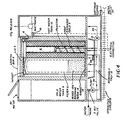
- the Figure 4 embodiment may be used.
- This Figure 4 embodiment differs from the Figure 3 embodiment in that water removed from the water holding tank 10 will first travel through conduit 64 to the heat exchange coils 3.
- This arrangement again allows the water to be cooled to a temperature such that downstream operations of the water treatment apparatus will not be adversely affected. From the heat exchange coils 3, the water may travel through conduit 66 to the second section or filter 2 of the disposable cartridge 40.
- This second section or filter 2 of the disposable cartridge 40 has a mixed ion-exchange resin 14 contained therein.
- This resin 14 will partially remove nitrates, sulfates and sodium ions from the water. As the water first passes through the heat exchange coils and is cooled in temperature before contacting this resin 14, damage to the resin is avoided. After water passes through the second section or filter 2, it will be discharged through conduit 68. As the water travels through this conduit, it will pass through an air-cooled section 15. This air-cooled section 15 further reduces the temperature of the water prior to feeding it to the downstream dispensing portion.
- the water treatment apparatus of the present invention removes hardness and some metal impurities from the water.
- the bulk of any chlorine is also stripped and removed in the holding tank 10.
- the holding tank 10 ensures sterilization of the water.
- the second section or filter 2 of the disposable cartridge 40 provides for removal of suspended solids and dissolved hydrocarbons in the water.
- limited ion exchange for sulfates, nitrates and sodium can be included in the water treatment apparatus of the instant invention as shown in the Figure 4 embodiment.
- a mixed ion exchange resin 14 is needed in such an arrangement as these components cannot be removed by a less sophisticated means.
- Heat recuperation in the instant device ensures a reasonable energy utilization of the device.
- the electrical heating element 4 of the instant invention is set by a control 16 such that an adequate temperature may be maintained in the head-space above the first section or reactor 1 of the disposable cartridge 40.
- a timer 17 may be provided in the device of the instant invention. This timer 17 is actuated by operation of the dispenser valves (not shown) and will measure actual dispensing hours or amount of water dispensed. If actual dispensing hours are measured, the timer may then determine the volume of water treated. After a predetermined amount of water has been dispensed by this device, the timer will provide a warning signal so that a user will be notified that the disposable cartridge 40 should be replaced. After a critical time has elapsed, the timer 17 will provide for cutting-off the operation of water pump 11 such that the water treatment apparatus is inoperable. The apparatus may be reactuated by replacement of the spent cartridge 40 with a new cartridge.
- the apparatus of the present invention will reduce water hardness while ensuring water sterility and removing water impurities which are not normally removed by conventional post-mix dispensers. Such purification of water has heretobefore only been attainable in bottling plant arrangements.
- the device of the instant invention avoids the use of large and complicated arrangements which have been used in bottling plant arrangements and thus may be used in small dispensing devices.
- the device of the instant invention requires no process control apart from a thermostat and thus is relatively simple to maintain and operate. Further, as the disposable cartridge 40 is relatively simple and as the nondisposable components of the apparatus require little maintenance, the device is relatively inexpensive to manufacture and to maintain but will permit desired treatment of water. Accordingly, this device can economically treat small quantities of water for beverage dispensing purposes without entailing high capital expenditures. This device will be effective for a wide range of water quality without requiring adjustments thereto.
Landscapes
- Organic Chemistry (AREA)
- Chemical & Material Sciences (AREA)
- Life Sciences & Earth Sciences (AREA)
- Hydrology & Water Resources (AREA)
- Engineering & Computer Science (AREA)
- Environmental & Geological Engineering (AREA)
- Water Supply & Treatment (AREA)
- Clinical Laboratory Science (AREA)
- Health & Medical Sciences (AREA)
- Water Treatment By Sorption (AREA)
- Physical Water Treatments (AREA)
- Separation Using Semi-Permeable Membranes (AREA)
- Non-Alcoholic Beverages (AREA)
- Treatment Of Water By Ion Exchange (AREA)
- Heat Treatment Of Water, Waste Water Or Sewage (AREA)
- Devices For Dispensing Beverages (AREA)
Claims (11)
Priority Applications (1)
| Application Number | Priority Date | Filing Date | Title |
|---|---|---|---|
| AT88117097T ATE64361T1 (de) | 1987-10-15 | 1988-10-14 | Vorrichtung zur vollstaendigen wasserbehandlung fuer getraenkespender. |
Applications Claiming Priority (2)
| Application Number | Priority Date | Filing Date | Title |
|---|---|---|---|
| US07/108,703 US4844796A (en) | 1987-10-15 | 1987-10-15 | Full water treatment apparatus for use in soft drink dispensing system |
| US108703 | 1987-10-15 |
Publications (3)
| Publication Number | Publication Date |
|---|---|
| EP0312079A2 EP0312079A2 (de) | 1989-04-19 |
| EP0312079A3 EP0312079A3 (en) | 1989-11-29 |
| EP0312079B1 true EP0312079B1 (de) | 1991-06-12 |
Family
ID=22323616
Family Applications (1)
| Application Number | Title | Priority Date | Filing Date |
|---|---|---|---|
| EP88117097A Expired - Lifetime EP0312079B1 (de) | 1987-10-15 | 1988-10-14 | Vorrichtung zur vollständigen Wasserbehandlung für Getränkespender |
Country Status (8)
| Country | Link |
|---|---|
| US (1) | US4844796A (de) |
| EP (1) | EP0312079B1 (de) |
| JP (1) | JPH0636912B2 (de) |
| CN (1) | CN1017521B (de) |
| AT (1) | ATE64361T1 (de) |
| AU (1) | AU600605B2 (de) |
| CA (1) | CA1313503C (de) |
| DE (1) | DE3863267D1 (de) |
Families Citing this family (28)
| Publication number | Priority date | Publication date | Assignee | Title |
|---|---|---|---|---|
| FR2687660B1 (fr) * | 1992-02-24 | 1994-09-16 | Cogia | Procede et dispositif de demineralisation de l'eau. |
| US5531908A (en) * | 1993-08-20 | 1996-07-02 | Suntory Limited | Germ-free liquid dispenser |
| US5776333A (en) * | 1995-03-31 | 1998-07-07 | The Coca-Cola Company | On premise water treatment apparatus |
| US5858248A (en) * | 1995-03-31 | 1999-01-12 | The Coca-Cola Company | On premise water treatment method for use in a post-mix beverage dispenser |
| US5611937A (en) * | 1995-05-12 | 1997-03-18 | The Coca-Cola Company | Water Treating apparatus and method |
| IL121885A0 (en) | 1997-10-05 | 1998-03-10 | Soda Club Holdings Nv | Water purifying and dispensing apparatus |
| US6312589B1 (en) | 1997-12-23 | 2001-11-06 | The Coca-Cola Company | Apparatus arranged to provide controllable water treatment customized to the conditions of water supplied to a beverage dispenser |
| US6183637B1 (en) | 1998-07-23 | 2001-02-06 | Seh America, Inc. | Resin trap device for use in ultrapure water systems and method of purifying water using same |
| AU6503500A (en) * | 1999-07-28 | 2001-02-19 | Juzer Jangbarwala | Dealkalization method and apparatus for use with point-of-purchase carbonated beverage dispensers |
| US6264830B1 (en) | 1999-08-13 | 2001-07-24 | The Coca-Cola Company | On premise water treatment system and method |
| GB9921659D0 (en) * | 1999-09-14 | 1999-11-17 | Imi Cornelius Uk Ltd | Water treatment |
| US6495049B1 (en) | 1999-10-21 | 2002-12-17 | The Coca-Cola Company | On premise water treatment system with temperature control water release and method |
| WO2002042220A1 (de) * | 2000-11-23 | 2002-05-30 | Watercryst Chemiefreie Wasserbehandlung Gmbh | Einrichtung zur behandlung von trinkwasser |
| AT409261B (de) * | 2000-11-23 | 2002-07-25 | Leiter Klaus Dr | Einrichtung zur physikalischen behandlung von trinkwasser |
| US6610210B2 (en) * | 2001-06-22 | 2003-08-26 | The Coca-Cola Company | Disposable cartridge for on-premises water treatment system |
| GB0201351D0 (en) * | 2002-01-22 | 2002-03-13 | Imi Cornelius Uk Ltd | Liquid purification method and apparatus |
| BR0215691A (pt) * | 2002-05-07 | 2005-02-01 | Coca Cola Co | Aparelho para tratamento de água, e, método para esterilizar o mesmo |
| US6915924B1 (en) | 2003-11-10 | 2005-07-12 | Robert J. Noiseux | Bottled water source to soft drink dispenser machine |
| WO2006097791A1 (en) * | 2004-10-21 | 2006-09-21 | Diageo North America, Inc. | Purified beverage products and processes for making the same |
| CN100441519C (zh) * | 2005-05-26 | 2008-12-10 | 北京化工大学 | 一种去除水体中含氯有机物的方法及脱氯材料 |
| WO2013151618A2 (en) * | 2012-04-02 | 2013-10-10 | Hydronovation, Inc. | Hybrid softener |
| KR101770481B1 (ko) * | 2015-11-30 | 2017-09-05 | 엘지전자 주식회사 | 정수기 |
| KR102539477B1 (ko) * | 2016-05-04 | 2023-06-05 | 엘지전자 주식회사 | 정수기 |
| CN106495418A (zh) * | 2016-12-30 | 2017-03-15 | 桂林市逸仙中学 | 一种生活污水处理系统 |
| KR101948726B1 (ko) * | 2017-07-13 | 2019-02-18 | 엘지전자 주식회사 | 정수기 |
| KR102095026B1 (ko) * | 2017-07-20 | 2020-03-30 | 엘지전자 주식회사 | 정수기 |
| DE102018112362A1 (de) * | 2018-05-23 | 2019-11-28 | Grohe Ag | Vorrichtung und Verfahren zur Reinigung einer Trinkwasseraufbereitungsanlage |
| US20250196031A1 (en) * | 2023-12-19 | 2025-06-19 | Hydration Labs, Inc. | Filter life detection via dynamic pressure measurement |
Family Cites Families (10)
| Publication number | Priority date | Publication date | Assignee | Title |
|---|---|---|---|---|
| US3873445A (en) * | 1972-12-05 | 1975-03-25 | Altair Ind | Apparatus for reducing toilet effluents to useable liquids |
| US3974075A (en) * | 1975-07-03 | 1976-08-10 | General American Transportation Corporation | Toilet system |
| US4066550A (en) * | 1975-08-11 | 1978-01-03 | Stanley Beaumont | Apparatus for sewage treatment with countercurrent heat transfer means |
| US4120787A (en) * | 1976-12-29 | 1978-10-17 | United Technologies Corporation | Fuel cell water conditioning process and system and deaerator for use therein |
| US4483769A (en) * | 1983-01-13 | 1984-11-20 | Aquaria, Inc. | Filter cartridge |
| US4606823A (en) * | 1983-11-03 | 1986-08-19 | Lucas Iii Charles E | Water filtering apparatus |
| US4518503A (en) * | 1984-03-29 | 1985-05-21 | Intercontinental Water Corp. | Water purification method and device |
| US4541926A (en) * | 1984-07-20 | 1985-09-17 | Stanley Bedford F | Portable water conditioner having separate containers for different conditioning materials |
| US4759474A (en) * | 1985-06-24 | 1988-07-26 | Everpure, Inc. | Beverage dispensing system and filter cartridge therefor |
| DE3535677A1 (de) * | 1985-10-05 | 1987-04-16 | Erich Alhaeuser | Patrone fuer ein drucklos arbeitendes geraet zur verbesserung der qualitaet von trinkwasser |
-
1987
- 1987-10-15 US US07/108,703 patent/US4844796A/en not_active Expired - Fee Related
-
1988
- 1988-10-13 AU AU23739/88A patent/AU600605B2/en not_active Ceased
- 1988-10-14 AT AT88117097T patent/ATE64361T1/de not_active IP Right Cessation
- 1988-10-14 EP EP88117097A patent/EP0312079B1/de not_active Expired - Lifetime
- 1988-10-14 CN CN88107085A patent/CN1017521B/zh not_active Expired
- 1988-10-14 CA CA000580184A patent/CA1313503C/en not_active Expired - Fee Related
- 1988-10-14 DE DE8888117097T patent/DE3863267D1/de not_active Expired - Lifetime
- 1988-10-14 JP JP63257385A patent/JPH0636912B2/ja not_active Expired - Fee Related
Also Published As
| Publication number | Publication date |
|---|---|
| CN1017521B (zh) | 1992-07-22 |
| CN1032773A (zh) | 1989-05-10 |
| JPH01139185A (ja) | 1989-05-31 |
| EP0312079A3 (en) | 1989-11-29 |
| US4844796A (en) | 1989-07-04 |
| CA1313503C (en) | 1993-02-09 |
| ATE64361T1 (de) | 1991-06-15 |
| AU600605B2 (en) | 1990-08-16 |
| DE3863267D1 (de) | 1991-07-18 |
| JPH0636912B2 (ja) | 1994-05-18 |
| EP0312079A2 (de) | 1989-04-19 |
| AU2373988A (en) | 1989-04-20 |
Similar Documents
| Publication | Publication Date | Title |
|---|---|---|
| EP0312079B1 (de) | Vorrichtung zur vollständigen Wasserbehandlung für Getränkespender | |
| US6451211B1 (en) | On premise water treatment method for use in a post mix beverage dispenser | |
| US6416673B2 (en) | On premise water treatment system and method | |
| US5776333A (en) | On premise water treatment apparatus | |
| US4957624A (en) | Method of and arrangement for purifying contaminated water | |
| EP1228003B1 (de) | Verfahren und vorrichtung zur lokalen wasserbehandlung mit temperaturgesteuerter wasserabgabe | |
| US5039402A (en) | Water purifier | |
| WO1996030309A9 (en) | On premise water treatment method | |
| US20050247609A1 (en) | Fluid treatment system | |
| US6251172B1 (en) | Portable water recovery and dispensing apparatus | |
| EP1086046A1 (de) | Vorrichtung zur behandlung von wasser | |
| KR19980069541A (ko) | 물분배기의 살균장치 | |
| JPS60248284A (ja) | 水の浄化殺菌装置 | |
| JPH01310787A (ja) | 冷熱水の生成システム | |
| RU2289546C2 (ru) | Самодезинфицирующееся устройство для обработки воды с резервуаром для очищенной воды, включающим нагревательный элемент | |
| KR200333468Y1 (ko) | 냉온 정수기 구조 | |
| ZA200202224B (en) | On premise water treatment system with temperature control water release and method. | |
| KR19980069530A (ko) | 물분배기의 취수가변장치 | |
| KR19980069542A (ko) | 물분배기의 취수장치 | |
| KR19990005673A (ko) | 물분배기 | |
| KR19980069518A (ko) | 물분배기용 살균램프의 보호장치 |
Legal Events
| Date | Code | Title | Description |
|---|---|---|---|
| PUAI | Public reference made under article 153(3) epc to a published international application that has entered the european phase |
Free format text: ORIGINAL CODE: 0009012 |
|
| AK | Designated contracting states |
Kind code of ref document: A2 Designated state(s): AT CH DE FR GB IT LI LU SE |
|
| PUAL | Search report despatched |
Free format text: ORIGINAL CODE: 0009013 |
|
| AK | Designated contracting states |
Kind code of ref document: A3 Designated state(s): AT CH DE FR GB IT LI LU SE |
|
| 17P | Request for examination filed |
Effective date: 19891117 |
|
| 17Q | First examination report despatched |
Effective date: 19900713 |
|
| GRAA | (expected) grant |
Free format text: ORIGINAL CODE: 0009210 |
|
| AK | Designated contracting states |
Kind code of ref document: B1 Designated state(s): AT CH DE FR GB IT LI LU SE |
|
| REF | Corresponds to: |
Ref document number: 64361 Country of ref document: AT Date of ref document: 19910615 Kind code of ref document: T |
|
| ITF | It: translation for a ep patent filed | ||
| REF | Corresponds to: |
Ref document number: 3863267 Country of ref document: DE Date of ref document: 19910718 |
|
| ET | Fr: translation filed | ||
| PLBE | No opposition filed within time limit |
Free format text: ORIGINAL CODE: 0009261 |
|
| STAA | Information on the status of an ep patent application or granted ep patent |
Free format text: STATUS: NO OPPOSITION FILED WITHIN TIME LIMIT |
|
| 26N | No opposition filed | ||
| EPTA | Lu: last paid annual fee | ||
| EAL | Se: european patent in force in sweden |
Ref document number: 88117097.1 |
|
| PGFP | Annual fee paid to national office [announced via postgrant information from national office to epo] |
Ref country code: LU Payment date: 19950901 Year of fee payment: 8 |
|
| PGFP | Annual fee paid to national office [announced via postgrant information from national office to epo] |
Ref country code: SE Payment date: 19950918 Year of fee payment: 8 |
|
| PG25 | Lapsed in a contracting state [announced via postgrant information from national office to epo] |
Ref country code: LU Free format text: LAPSE BECAUSE OF NON-PAYMENT OF DUE FEES Effective date: 19961014 |
|
| PG25 | Lapsed in a contracting state [announced via postgrant information from national office to epo] |
Ref country code: SE Effective date: 19961015 |
|
| EUG | Se: european patent has lapsed |
Ref document number: 88117097.1 |
|
| PGFP | Annual fee paid to national office [announced via postgrant information from national office to epo] |
Ref country code: CH Payment date: 20010917 Year of fee payment: 14 |
|
| PGFP | Annual fee paid to national office [announced via postgrant information from national office to epo] |
Ref country code: AT Payment date: 20010925 Year of fee payment: 14 |
|
| PGFP | Annual fee paid to national office [announced via postgrant information from national office to epo] |
Ref country code: FR Payment date: 20011011 Year of fee payment: 14 |
|
| REG | Reference to a national code |
Ref country code: GB Ref legal event code: IF02 |
|
| PGFP | Annual fee paid to national office [announced via postgrant information from national office to epo] |
Ref country code: GB Payment date: 20020925 Year of fee payment: 15 |
|
| PG25 | Lapsed in a contracting state [announced via postgrant information from national office to epo] |
Ref country code: AT Free format text: LAPSE BECAUSE OF NON-PAYMENT OF DUE FEES Effective date: 20021014 |
|
| PGFP | Annual fee paid to national office [announced via postgrant information from national office to epo] |
Ref country code: DE Payment date: 20021017 Year of fee payment: 15 |
|
| PG25 | Lapsed in a contracting state [announced via postgrant information from national office to epo] |
Ref country code: LI Free format text: LAPSE BECAUSE OF NON-PAYMENT OF DUE FEES Effective date: 20021031 Ref country code: CH Free format text: LAPSE BECAUSE OF NON-PAYMENT OF DUE FEES Effective date: 20021031 |
|
| REG | Reference to a national code |
Ref country code: CH Ref legal event code: PL |
|
| PG25 | Lapsed in a contracting state [announced via postgrant information from national office to epo] |
Ref country code: FR Free format text: LAPSE BECAUSE OF NON-PAYMENT OF DUE FEES Effective date: 20030630 |
|
| REG | Reference to a national code |
Ref country code: FR Ref legal event code: ST |
|
| PG25 | Lapsed in a contracting state [announced via postgrant information from national office to epo] |
Ref country code: GB Free format text: LAPSE BECAUSE OF NON-PAYMENT OF DUE FEES Effective date: 20031014 |
|
| PG25 | Lapsed in a contracting state [announced via postgrant information from national office to epo] |
Ref country code: DE Free format text: LAPSE BECAUSE OF NON-PAYMENT OF DUE FEES Effective date: 20040501 |
|
| GBPC | Gb: european patent ceased through non-payment of renewal fee |
Effective date: 20031014 |
|
| PG25 | Lapsed in a contracting state [announced via postgrant information from national office to epo] |
Ref country code: IT Free format text: LAPSE BECAUSE OF NON-PAYMENT OF DUE FEES;WARNING: LAPSES OF ITALIAN PATENTS WITH EFFECTIVE DATE BEFORE 2007 MAY HAVE OCCURRED AT ANY TIME BEFORE 2007. THE CORRECT EFFECTIVE DATE MAY BE DIFFERENT FROM THE ONE RECORDED. Effective date: 20051014 |