EP0311992B1 - Verfahren und Vorrichtung zur Russoxidation in Dieselmotoren - Google Patents
Verfahren und Vorrichtung zur Russoxidation in Dieselmotoren Download PDFInfo
- Publication number
- EP0311992B1 EP0311992B1 EP88116890A EP88116890A EP0311992B1 EP 0311992 B1 EP0311992 B1 EP 0311992B1 EP 88116890 A EP88116890 A EP 88116890A EP 88116890 A EP88116890 A EP 88116890A EP 0311992 B1 EP0311992 B1 EP 0311992B1
- Authority
- EP
- European Patent Office
- Prior art keywords
- exhaust gas
- reactor
- heat
- catalytic
- transport gas
- Prior art date
- Legal status (The legal status is an assumption and is not a legal conclusion. Google has not performed a legal analysis and makes no representation as to the accuracy of the status listed.)
- Expired - Lifetime
Links
Images


Classifications
-
- F—MECHANICAL ENGINEERING; LIGHTING; HEATING; WEAPONS; BLASTING
- F01—MACHINES OR ENGINES IN GENERAL; ENGINE PLANTS IN GENERAL; STEAM ENGINES
- F01N—GAS-FLOW SILENCERS OR EXHAUST APPARATUS FOR MACHINES OR ENGINES IN GENERAL; GAS-FLOW SILENCERS OR EXHAUST APPARATUS FOR INTERNAL-COMBUSTION ENGINES
- F01N3/00—Exhaust or silencing apparatus having means for purifying, rendering innocuous, or otherwise treating exhaust
- F01N3/08—Exhaust or silencing apparatus having means for purifying, rendering innocuous, or otherwise treating exhaust for rendering innocuous
-
- F—MECHANICAL ENGINEERING; LIGHTING; HEATING; WEAPONS; BLASTING
- F01—MACHINES OR ENGINES IN GENERAL; ENGINE PLANTS IN GENERAL; STEAM ENGINES
- F01N—GAS-FLOW SILENCERS OR EXHAUST APPARATUS FOR MACHINES OR ENGINES IN GENERAL; GAS-FLOW SILENCERS OR EXHAUST APPARATUS FOR INTERNAL-COMBUSTION ENGINES
- F01N3/00—Exhaust or silencing apparatus having means for purifying, rendering innocuous, or otherwise treating exhaust
- F01N3/02—Exhaust or silencing apparatus having means for purifying, rendering innocuous, or otherwise treating exhaust for cooling, or for removing solid constituents of, exhaust
- F01N3/021—Exhaust or silencing apparatus having means for purifying, rendering innocuous, or otherwise treating exhaust for cooling, or for removing solid constituents of, exhaust by means of filters
- F01N3/023—Exhaust or silencing apparatus having means for purifying, rendering innocuous, or otherwise treating exhaust for cooling, or for removing solid constituents of, exhaust by means of filters using means for regenerating the filters, e.g. by burning trapped particles
- F01N3/0233—Exhaust or silencing apparatus having means for purifying, rendering innocuous, or otherwise treating exhaust for cooling, or for removing solid constituents of, exhaust by means of filters using means for regenerating the filters, e.g. by burning trapped particles periodically cleaning filter by blowing a gas through the filter in a direction opposite to exhaust flow, e.g. exposing filter to engine air intake
-
- F—MECHANICAL ENGINEERING; LIGHTING; HEATING; WEAPONS; BLASTING
- F01—MACHINES OR ENGINES IN GENERAL; ENGINE PLANTS IN GENERAL; STEAM ENGINES
- F01N—GAS-FLOW SILENCERS OR EXHAUST APPARATUS FOR MACHINES OR ENGINES IN GENERAL; GAS-FLOW SILENCERS OR EXHAUST APPARATUS FOR INTERNAL-COMBUSTION ENGINES
- F01N13/00—Exhaust or silencing apparatus characterised by constructional features
- F01N13/009—Exhaust or silencing apparatus characterised by constructional features having two or more separate purifying devices arranged in series
-
- F—MECHANICAL ENGINEERING; LIGHTING; HEATING; WEAPONS; BLASTING
- F01—MACHINES OR ENGINES IN GENERAL; ENGINE PLANTS IN GENERAL; STEAM ENGINES
- F01N—GAS-FLOW SILENCERS OR EXHAUST APPARATUS FOR MACHINES OR ENGINES IN GENERAL; GAS-FLOW SILENCERS OR EXHAUST APPARATUS FOR INTERNAL-COMBUSTION ENGINES
- F01N3/00—Exhaust or silencing apparatus having means for purifying, rendering innocuous, or otherwise treating exhaust
- F01N3/02—Exhaust or silencing apparatus having means for purifying, rendering innocuous, or otherwise treating exhaust for cooling, or for removing solid constituents of, exhaust
- F01N3/021—Exhaust or silencing apparatus having means for purifying, rendering innocuous, or otherwise treating exhaust for cooling, or for removing solid constituents of, exhaust by means of filters
- F01N3/023—Exhaust or silencing apparatus having means for purifying, rendering innocuous, or otherwise treating exhaust for cooling, or for removing solid constituents of, exhaust by means of filters using means for regenerating the filters, e.g. by burning trapped particles
-
- F—MECHANICAL ENGINEERING; LIGHTING; HEATING; WEAPONS; BLASTING
- F01—MACHINES OR ENGINES IN GENERAL; ENGINE PLANTS IN GENERAL; STEAM ENGINES
- F01N—GAS-FLOW SILENCERS OR EXHAUST APPARATUS FOR MACHINES OR ENGINES IN GENERAL; GAS-FLOW SILENCERS OR EXHAUST APPARATUS FOR INTERNAL-COMBUSTION ENGINES
- F01N3/00—Exhaust or silencing apparatus having means for purifying, rendering innocuous, or otherwise treating exhaust
- F01N3/02—Exhaust or silencing apparatus having means for purifying, rendering innocuous, or otherwise treating exhaust for cooling, or for removing solid constituents of, exhaust
- F01N3/021—Exhaust or silencing apparatus having means for purifying, rendering innocuous, or otherwise treating exhaust for cooling, or for removing solid constituents of, exhaust by means of filters
- F01N3/023—Exhaust or silencing apparatus having means for purifying, rendering innocuous, or otherwise treating exhaust for cooling, or for removing solid constituents of, exhaust by means of filters using means for regenerating the filters, e.g. by burning trapped particles
- F01N3/0234—Exhaust or silencing apparatus having means for purifying, rendering innocuous, or otherwise treating exhaust for cooling, or for removing solid constituents of, exhaust by means of filters using means for regenerating the filters, e.g. by burning trapped particles using heat exchange means in the exhaust line
-
- F—MECHANICAL ENGINEERING; LIGHTING; HEATING; WEAPONS; BLASTING
- F01—MACHINES OR ENGINES IN GENERAL; ENGINE PLANTS IN GENERAL; STEAM ENGINES
- F01N—GAS-FLOW SILENCERS OR EXHAUST APPARATUS FOR MACHINES OR ENGINES IN GENERAL; GAS-FLOW SILENCERS OR EXHAUST APPARATUS FOR INTERNAL-COMBUSTION ENGINES
- F01N3/00—Exhaust or silencing apparatus having means for purifying, rendering innocuous, or otherwise treating exhaust
- F01N3/02—Exhaust or silencing apparatus having means for purifying, rendering innocuous, or otherwise treating exhaust for cooling, or for removing solid constituents of, exhaust
- F01N3/021—Exhaust or silencing apparatus having means for purifying, rendering innocuous, or otherwise treating exhaust for cooling, or for removing solid constituents of, exhaust by means of filters
- F01N3/023—Exhaust or silencing apparatus having means for purifying, rendering innocuous, or otherwise treating exhaust for cooling, or for removing solid constituents of, exhaust by means of filters using means for regenerating the filters, e.g. by burning trapped particles
- F01N3/025—Exhaust or silencing apparatus having means for purifying, rendering innocuous, or otherwise treating exhaust for cooling, or for removing solid constituents of, exhaust by means of filters using means for regenerating the filters, e.g. by burning trapped particles using fuel burner or by adding fuel to exhaust
-
- F—MECHANICAL ENGINEERING; LIGHTING; HEATING; WEAPONS; BLASTING
- F01—MACHINES OR ENGINES IN GENERAL; ENGINE PLANTS IN GENERAL; STEAM ENGINES
- F01N—GAS-FLOW SILENCERS OR EXHAUST APPARATUS FOR MACHINES OR ENGINES IN GENERAL; GAS-FLOW SILENCERS OR EXHAUST APPARATUS FOR INTERNAL-COMBUSTION ENGINES
- F01N3/00—Exhaust or silencing apparatus having means for purifying, rendering innocuous, or otherwise treating exhaust
- F01N3/02—Exhaust or silencing apparatus having means for purifying, rendering innocuous, or otherwise treating exhaust for cooling, or for removing solid constituents of, exhaust
- F01N3/021—Exhaust or silencing apparatus having means for purifying, rendering innocuous, or otherwise treating exhaust for cooling, or for removing solid constituents of, exhaust by means of filters
- F01N3/023—Exhaust or silencing apparatus having means for purifying, rendering innocuous, or otherwise treating exhaust for cooling, or for removing solid constituents of, exhaust by means of filters using means for regenerating the filters, e.g. by burning trapped particles
- F01N3/029—Exhaust or silencing apparatus having means for purifying, rendering innocuous, or otherwise treating exhaust for cooling, or for removing solid constituents of, exhaust by means of filters using means for regenerating the filters, e.g. by burning trapped particles by adding non-fuel substances to exhaust
-
- F—MECHANICAL ENGINEERING; LIGHTING; HEATING; WEAPONS; BLASTING
- F01—MACHINES OR ENGINES IN GENERAL; ENGINE PLANTS IN GENERAL; STEAM ENGINES
- F01N—GAS-FLOW SILENCERS OR EXHAUST APPARATUS FOR MACHINES OR ENGINES IN GENERAL; GAS-FLOW SILENCERS OR EXHAUST APPARATUS FOR INTERNAL-COMBUSTION ENGINES
- F01N5/00—Exhaust or silencing apparatus combined or associated with devices profiting by exhaust energy
- F01N5/04—Exhaust or silencing apparatus combined or associated with devices profiting by exhaust energy the devices using kinetic energy
-
- F—MECHANICAL ENGINEERING; LIGHTING; HEATING; WEAPONS; BLASTING
- F02—COMBUSTION ENGINES; HOT-GAS OR COMBUSTION-PRODUCT ENGINE PLANTS
- F02G—HOT GAS OR COMBUSTION-PRODUCT POSITIVE-DISPLACEMENT ENGINE PLANTS; USE OF WASTE HEAT OF COMBUSTION ENGINES; NOT OTHERWISE PROVIDED FOR
- F02G5/00—Profiting from waste heat of combustion engines, not otherwise provided for
- F02G5/02—Profiting from waste heat of exhaust gases
-
- F—MECHANICAL ENGINEERING; LIGHTING; HEATING; WEAPONS; BLASTING
- F01—MACHINES OR ENGINES IN GENERAL; ENGINE PLANTS IN GENERAL; STEAM ENGINES
- F01N—GAS-FLOW SILENCERS OR EXHAUST APPARATUS FOR MACHINES OR ENGINES IN GENERAL; GAS-FLOW SILENCERS OR EXHAUST APPARATUS FOR INTERNAL-COMBUSTION ENGINES
- F01N2430/00—Influencing exhaust purification, e.g. starting of catalytic reaction, filter regeneration, or the like, by controlling engine operating characteristics
-
- F—MECHANICAL ENGINEERING; LIGHTING; HEATING; WEAPONS; BLASTING
- F01—MACHINES OR ENGINES IN GENERAL; ENGINE PLANTS IN GENERAL; STEAM ENGINES
- F01N—GAS-FLOW SILENCERS OR EXHAUST APPARATUS FOR MACHINES OR ENGINES IN GENERAL; GAS-FLOW SILENCERS OR EXHAUST APPARATUS FOR INTERNAL-COMBUSTION ENGINES
- F01N2510/00—Surface coverings
-
- F—MECHANICAL ENGINEERING; LIGHTING; HEATING; WEAPONS; BLASTING
- F01—MACHINES OR ENGINES IN GENERAL; ENGINE PLANTS IN GENERAL; STEAM ENGINES
- F01N—GAS-FLOW SILENCERS OR EXHAUST APPARATUS FOR MACHINES OR ENGINES IN GENERAL; GAS-FLOW SILENCERS OR EXHAUST APPARATUS FOR INTERNAL-COMBUSTION ENGINES
- F01N3/00—Exhaust or silencing apparatus having means for purifying, rendering innocuous, or otherwise treating exhaust
- F01N3/02—Exhaust or silencing apparatus having means for purifying, rendering innocuous, or otherwise treating exhaust for cooling, or for removing solid constituents of, exhaust
- F01N3/021—Exhaust or silencing apparatus having means for purifying, rendering innocuous, or otherwise treating exhaust for cooling, or for removing solid constituents of, exhaust by means of filters
- F01N3/022—Exhaust or silencing apparatus having means for purifying, rendering innocuous, or otherwise treating exhaust for cooling, or for removing solid constituents of, exhaust by means of filters characterised by specially adapted filtering structure, e.g. honeycomb, mesh or fibrous
-
- F—MECHANICAL ENGINEERING; LIGHTING; HEATING; WEAPONS; BLASTING
- F01—MACHINES OR ENGINES IN GENERAL; ENGINE PLANTS IN GENERAL; STEAM ENGINES
- F01N—GAS-FLOW SILENCERS OR EXHAUST APPARATUS FOR MACHINES OR ENGINES IN GENERAL; GAS-FLOW SILENCERS OR EXHAUST APPARATUS FOR INTERNAL-COMBUSTION ENGINES
- F01N9/00—Electrical control of exhaust gas treating apparatus
-
- F—MECHANICAL ENGINEERING; LIGHTING; HEATING; WEAPONS; BLASTING
- F02—COMBUSTION ENGINES; HOT-GAS OR COMBUSTION-PRODUCT ENGINE PLANTS
- F02B—INTERNAL-COMBUSTION PISTON ENGINES; COMBUSTION ENGINES IN GENERAL
- F02B3/00—Engines characterised by air compression and subsequent fuel addition
- F02B3/06—Engines characterised by air compression and subsequent fuel addition with compression ignition
-
- Y—GENERAL TAGGING OF NEW TECHNOLOGICAL DEVELOPMENTS; GENERAL TAGGING OF CROSS-SECTIONAL TECHNOLOGIES SPANNING OVER SEVERAL SECTIONS OF THE IPC; TECHNICAL SUBJECTS COVERED BY FORMER USPC CROSS-REFERENCE ART COLLECTIONS [XRACs] AND DIGESTS
- Y02—TECHNOLOGIES OR APPLICATIONS FOR MITIGATION OR ADAPTATION AGAINST CLIMATE CHANGE
- Y02T—CLIMATE CHANGE MITIGATION TECHNOLOGIES RELATED TO TRANSPORTATION
- Y02T10/00—Road transport of goods or passengers
- Y02T10/10—Internal combustion engine [ICE] based vehicles
- Y02T10/12—Improving ICE efficiencies
Definitions
- the invention relates to a method according to the preamble of claim 1 and a device according to the preamble of claim 5.
- EP-A-0 158 625 describes a method of this kind for an internal combustion engine. There, heat is extracted from the exhaust gas both before and after the catalytic cleaning in order to maintain the optimal catalyst temperature. The respective heat extraction is controlled according to the driving conditions. In diesel engines, the exhaust gas is too low in some driving conditions to allow soot oxidation. As a result, this known method for soot oxidation in diesel engines is not suitable. A similar process is known from JP-A-60 93 110.
- a diesel engine produces significant amounts of soot.
- Soot is removed using mechanical filters that contain either a wire mesh or a ceramic structure. Soot particles separate on these filters. The problem with these filters is cleaning, since the soot particles gradually clog the filter so that the exhaust gas back pressure takes on impermissibly high values.
- the object of the invention is to ensure complete and continuous soot oxidation in the exhaust gas of a diesel engine in all driving conditions.
- This method differs from the prior art in that the heat removed from the exhaust gas is brought to a higher level and is supplied to the exhaust gas before the oxidation so as to increase the exhaust gas temperature to an optimal oxidation value.
- a cycle of the transport gas is made possible in that energy is removed from the transport gas by relaxation after the heat has been given off.
- the energy released during relaxation provides part of the energy required for compression.
- a closed circuit is made possible in that the expanded transport gas is returned to the circuit.
- the temperature control of the catalytic process is improved in that air is temporarily sucked in and compressed as a transport gas directly from the atmosphere and is released after the absorption of heat from the exhaust gas stream before the location of the catalytic reaction - in particular behind the turbomachine to relax the transport gas.
- overheating of the catalytic converter can thereby be ruled out by introducing cold atmospheric air into the circuit at a high exhaust gas temperature.
- a device according to the invention is characterized by the characterizing features of claim 5.
- This device differs from the prior art in that the exhaust gas through a heat recovery process before the reak Tor is heated to the catalytically reduced soot oxidation temperature.
- the heat recovery process provides that a transport gas takes heat from the exhaust gas following the reactor. This transport gas is compressed so that its enthalpy is increased. The compressed transport gas gives off heat to the relatively cold exhaust gas coming from the engine in a heat exchanger, so that this exhaust gas is heated to the reaction temperature for oxidation. The cooled transport gas is expanded in an expansion device and returned to the circuit. This cycle of the transport gas requires only a small mechanical energy, since the expansion device largely supplies the energy required for the compressor. The additional residual energy can be provided by a turbo machine with a bypass in the exhaust gas stream.
- the action of the catalytic material is ensured in that the catalytic material is applied as a coating on the reactor body.
- the mounting of the catalytic material is improved in that the catalytic material is provided in or on a carrier material.
- an additional burner device for heating the exhaust gas is arranged in front of the reactor.
- an existing, motor-independent heating device is additionally provided for heating the exhaust gas flow.
- the existing burner device e.g. external heating can also be used.
- a separate burner device could be saved.
- the invention provides that one or more screens of different mesh sizes and with a catalytic coating are arranged between the heat exchanger and the reactor in the exhaust gas stream. Preoxidation, especially large soot particles, also occurs here. This improves the effectiveness of the device.
- a high oxidation effect is achieved in that the reactor is filled with at least one element made of metallic material which is structured on the inside like a honeycomb and which is catalytically coated.
- the reactor is filled with at least one element made of non-metallic material which is structured on the inside like a honeycomb and which is catalytically coated.
- This non-metallic material can be ceramic.
- a large effective surface is achieved by filling the reactor with a catalytically coated wool made of a metallic or non-metallic material.
- the oxidation path for the exhaust gas stream can be enlarged in that at least one heat exchanger is catalytically coated on the exhaust gas-carrying side.
- the life of the device is increased in that the catalytic coating consists of precious metals.
- Another solution provides that the catalytic coating consists of rare earth metals.
- a high catalytic efficiency is achieved if the internal structures of the reactor have components or deformations to increase the turbulence of the exhaust gas flow.
- the catalytic effect within the turbulent agbas flow is increased due to the increased possibility of contacting.
- the heat balance of the device is improved in that the reactor is thermally insulated from the environment.
- a further improvement is achieved in that the reactor body is thermally insulated from the housing of the reactor.
- Heat losses can be further reduced in that the heat exchangers are thermally insulated from the environment.
- a further reduction in heat losses is achieved in that the inner structures of the heat exchangers are thermally insulated from the housing.
- the heat exchange is intensified by the fact that structures separating the flow boundary layer are built into the heat exchanger. In this way, a turbulent exhaust gas flow can also be achieved within the heat exchanger and thus a more intensive heat exchange.
- One proposal of the invention provides that the heat exchangers are designed as countercurrent heat exchangers.
- the heat exchangers are designed as micro-structural heat exchangers.
- a valve is installed in the pipes, which opens the circuit of the transport gas to the environment.
- cold air can be introduced into the circuit in order to bring about a cooling effect. This prevents damage to the catalytic converter.
- the additional energy for the compression can be provided in that a turbomachine with a regulated bypass, which draws drive energy for the compressor from the exhaust gas flow, is arranged in the exhaust pipe.
- the power consumption of the turbomachine can be controlled in the usual way via the bypass.
- valve which is arranged after the expansion device, is connected to the exhaust pipe via a pipe.
- thermocouples, pressure sensors and / or other sensors are provided for control signal acquisition.
- the control of the oxidation device can be connected to the motor control or integrated into it. Control interventions in the engine control are possible on the part of the oxidation device and vice versa. When the exhaust gas temperature drops, the engine output can be increased in order to eliminate unfavorable exhaust gas temperatures.
- valves Different controls of the valves are possible in that an electrical, mechanical, pneumatic or hydraulic actuation of the valves and the bypass valve of the turbomachine is provided.
- control / regulating device providing output variables for regulating the drive motor. So you can also in transient operating states ensure optimal oxidation.
- the exhaust manifold 1 of a diesel engine M is shown.
- a plurality of exhaust manifolds can also be present, which are then each equipped with a soot oxidation device.
- a first heat exchanger W1 is installed in the exhaust manifold.
- a reactor 2 for soot oxidation is connected to the same.
- a second heat exchanger W2 then follows, from which the exhaust gases are removed in a line 3.
- the reactor 2 contains a catalytic material which is applied as a layer on the reactor body and optionally mixed with a carrier substance.
- the catalytic material lowers the combustion temperature of the soot to around 300 ° C or even less.
- the honeycomb structure of the reactor body 21 can be seen. It can be a metallic, non-metallic, in particular ceramic, an ordered or more or less disordered structure. This structure is coated with the catalyst or the catalyst is incorporated into this structure. The structure has such a configuration that it removes the boundary layer from the exhaust gas flow.
- the heat exchangers W1 and W2 are connected to one another via lines 4, 5 and a conveying device 6.
- the conveyor normally includes a compressor and an expansion device.
- the expansion device can be designed as a turbine and sit with the compressor on a common shaft driven by an exhaust gas turbine or a motor.
- an additional burner device 8 is provided.
- a heating device that is available for other purposes, such as external heating, can also be provided as the burner device.
- a chemical heat accumulator 14 can also be provided. The oxidation process can thus be initiated in any case.
- the heat exchanger W2 makes it possible to extract so much heat from the exhaust gas that the temperature in line 3 drops to approximately 160.degree.
- the exchange medium or transport gas is then heated by adiabatic compression to such an extent that the heat exchanger W1 raises the temperature of the exhaust gas to a value of approximately 350 ° C.
- the oxidation can thus start reliably.
- the transport gas must be expanded in the return line, which is expediently carried out via a turbine which is coupled to the compressor. As a result, the drive power for the compressor can be kept small.
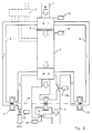
- Fig. 2 shows a modified embodiment of the invention.
- a catalytically coated screen 9 is arranged for pre-oxidation of the largest soot particles occurring.
- the size of the soot particles entering the reactor can be determined by the mesh size of the sieve 9 such that these particles are completely oxidized on the way through the reactor.
- particles such as larger metal debris, which are harmful to the reactor can be retained at this point.
- This screen can be cleaned as part of normal vehicle inspection.
- valve 10a which opens into the atmosphere or which is connected to the exhaust line 3 via a line.
- a valve 10 is located on the inlet side of the compressor 7 and also enables the circuit to be opened to the atmosphere.
- a flow machine 12 with a bypass 15 is located within the exhaust line 3.
- the compressor 7, the flow machine 12 and the expansion device 13 can be arranged on a common shaft 16 or can be coupled in some other way. The mechanical energy released in the expansion device 13 can thus be used directly to drive the compressor 7. Only the necessary Additional energy is provided by the fluid machine 12.
- a control device 17 receives input signals from probes for temperature, pressure and other operating parameters. This control device is used to control the oxidation device. But it can also give control signals to the engine control. So the engine can be controlled depending on the state of the oxidizer. You can change the engine power to ensure an optimal exhaust gas temperature.
- valve 10 If excessively hot exhaust gases occur in certain driving conditions, cold atmospheric air can be introduced through the valve 10.
- the circuit can thus be used to cool the exhaust gas flow.
- the heated air is exhausted through the valve 10a after expansion.
- the recirculation into the exhaust gas line 3 rules out interfering effects of this heated air.
- the valves 10 and 10a can be controlled depending on the respective operating state.
Landscapes
- Engineering & Computer Science (AREA)
- Chemical & Material Sciences (AREA)
- Combustion & Propulsion (AREA)
- Mechanical Engineering (AREA)
- General Engineering & Computer Science (AREA)
- Exhaust Gas After Treatment (AREA)
- Physical Or Chemical Processes And Apparatus (AREA)
- Processes For Solid Components From Exhaust (AREA)
- Chimneys And Flues (AREA)
- Catalysts (AREA)
- Exhaust Gas Treatment By Means Of Catalyst (AREA)
Description
- Die Erfindung betrifft ein Verfahren nach dem Oberbegriff des Anspruchs 1 und eine Vorrichtung nach dem Oberbegriff des Anspruchs 5.
- Die EP-A-0 158 625 beschreibt ein Verfahren dieser Art für einen Verbrennungsmotor. Dort wird dem Abgas sowohl vor als auch nach der katalytischen Reinigung Wärme entzogen, um die optimale Katalysatortemperatur zu erhalten. Der jeweilige Wärmeentzug wird entsprechend den Fahrzuständen gesteuert. Bei Dieselmotoren hat das Abgas in manchen Fahrzuständen eine zu niedrige Temperatur, um ein Rußoxidation zuzulassen. Infolgedessen ist dieses bekannte Verfahren zur Rußoxidation bei Dieselmotoren nicht geeignet. Ein ähnliches Verfahren ist aus der JP-A-60 93 110 bekannt.
- Ein Dieselmotor produziert erhebliche Rußmengen. Für den Gehalt dieser Rußmengen im Abgas bestehen bekanntlich Vorschriften. Es ist zu erwarten, daß diese Vorschriften aus Umweltgründen immer strenger werden, so daß die zulässigen Rußwerte im Abgas noch weiter abgesenkt werden müssen.
- Das Ausscheiden von Ruß erfolgt mit Hilfe mechanischer Filter, die entweder ein Drahtgeflecht oder eine keramische Struktur enthalten. An diesen Filtern scheiden sich Rußpartikel ab. Das Problem dieser Filter ist die Reinigung, da die Rußpartikel das Filter allmählich zusetzen, so daß der Abgasgegendruck unzulässig hohe Werte annimmt.
- Ein einfaches Verbrennen der Rußpartikel ist erst bei Temperaturen oberhalb 650 °C möglich. Die Abgastemperatur eines Dieselmotors erreicht nur in bestimmten Fahrzuständen diesen Wert. In vielen Fahrzuständen beträgt die Abgastemperatur nur 200 °C und liegt also wesentlich unter der Verbrennungstemperatur der Rußpartikel. Infolgedessen ist dieser einfache Weg nicht möglich.
- Es ist bereits bekannt, die Verbrennungstemperatur der Rußteilchen durch Einspritzen von Oxidationsmitteln herabzusetzen. Hierbei kann die Verbrennungstemperatur auf Werte unter 300 °C gesenkt werden. Jedoch auch dann gibt es noch Fahrzustände, in denen die Abgastemperatur niedriger ist. Außerdem erzeugen die Oxidattionshilfsmittel umweltschädliche Rückstände, insbesondere Schwermetallrückstände, so daß dieses Verfahren keine wirksame Abhilfe verspricht.
- Bekannt ist auch das Aufheizen der Abgase durch Brenner. Dieses Verfahren ist sehr energieaufwendig.
- Aufgabe der Erfindung ist die Sicherstellung einer vollständigen und kontinuierliche Rußoxidation im Abgas eines Dieselmotors bei allen Fahrzuständen.
- Diese Aufgabe wird nach der Erfindung durch die kennzeichnenden Merkmale der Ansprüche 1 und 5 gelöst.
- Dieses Verfahren unterscheidet sich insofern vom Stand der Technik, als die dem Abgas entnommene Wärme auf ein höheres Niveau gebracht und dem Abgas vor der Oxidation zugeführt wird, um so die Abgastemperatur auf einen optimalen Oxidationswert zu erhöhen.
- Ein Kreislauf des Transportgases wird dadurch ermöglicht, daß dem Transportgas nach der Wärmeabgabe Energie durch Entspannung entzogen wird. Die bei der Enspannung freiwerdende Energie liefert einen Teil der für die Verdichtung notwendigen Energie.
- Ein geschlossener Kreislauf wird dadurch ermöglicht, daß das entpannte Transportgas in den Kreislauf zurückgeführt wird.
- Die Temperaturführung des katalytischen Prozesses wird dadurch verbessert, daß zeitweise Luft als Transportgas unmittelbar aus der Atmosphäre angesaugt und verdichtet wird und nach einer Wärmeaufnahme aus dem Abgasstrom vor dem Ort der katalytischen Reaktion - insbesondere hinter der Strömungsmaschine zur Entspannung des Transportgases freigesetzt wird. Dadurch läßt sich insbesondere eine Überhitzung des Katalysators ausschließen, indem bei hoher Abgastemperatur kalte atmosphärische Luft in den Kreislauf eingeleitet wird.
- Eine Vorrichtung nach der Erfindung zeichnet sich durch die kennzeichnenden Merkmale des Anspruchs 5 aus.
- Diese Vorrichtung unterscheidet sich insofern vom Stand der Technik, als das Abgas durch einen Wärmerückgewinnungsprozeß vor dem Reak tor auf die katalytisch erniedrigte Rußoxidationstemperatur erhitzt wird. Der Wärmerückgewinnungsprozeß sieht vor, daß ein Transportgas im Anschluß an den Reaktor Wärme aus dem Abgas entnimmt. Dieses Transportgas wird verdichtet, so daß seine Enthalpie erhöht wird. Das komprimierte Transportgas gibt in einem Wärmetauscher Wärme an das relativ kalte Abgas, das aus dem Motor kommt, ab, so daß dieses Abgas auf die Reaktonstemperatur für die Oxidation erwärmt wird. Das abgekühlte Transportgas wird in einer Expansionsvorrichtung entspannt und in den Kreislauf zurückgeführt. Dieser Kreislauf des Transportgases erfordert nur eine geringe mechanische Energie, da die Entspannungsvorrichtung weitgehend die für den Kompressor erforderliche Energie liefert. Die zusätzliche Restenergie kann von einer Strömungsmaschine mit Bypass im Abgasstrom bereitgestellt werden.
- Die Einwirkung des katalytischen Werkstoffs wird dadurch sichergestellt, daß der katalytische Werkstoff als Beschichtung auf den Reaktorkörper aufgetragen ist.
- Die Halterung des katalytischen Werkstoffs ist dadurch verbessert, daß der katalytische Werkstoff in oder auf einem Trägerwerkstoff vorgesehen ist.
- Zur Einleitung der Rußverbrennung beim Kaltstart oder im Anfahrbetrieb ist vorgesehen, daß vor dem Reaktor eine zusätzliche Brennereinrichtung zur Erhitzung des Abgases angeordnet ist.
- Im Rahmen der Erfinding ist auch vorgesehen, daß eine bereits vorhandene, motorunabhängige Heizeinrichtung zusätzlich zur Erwärmung des Abgasstromes vorgesehen ist. Dadurch kann die vorhandene Brennereinrichtung, z.B. eine Fremdheizung zusätzlich genutzt werden. Eine gesonderte Brennereinrichtung könnte eingespart werden.
- Eine andere Einleitung der Verbrennung ist dadurch möglich, daß ein chemischer Wärmespeicher vor dem Reaktor mit dem Abgasstrom gekoppelt ist.
- Zur Abtrennung störender Partikel aus dem Abgasstrom sieht die Erfindung vor, daß zwischen dem Wärmetauscher und dem Reaktor im Abgasstrom ein oder mehrere Siebe unterschiedlicher Maschenweite und mit katalytischer Beschichtung angeordnet sind. Hier erfolgt auch eine Voroxidation, insbesondere großer Rußteilchen. Hierdurch wird die Wirkung der Vorrichtung verbessert.
- Eine hohe Oxidationswirkung erzielt man dadurch, daß der Reaktor mit mindestens einem, innen wabenähnlich strukturierten Element aus metallischem Werkstoff gefüllt ist, das katalytisch beschichtet ist.
- In anderer Weise ist vorgesehen, daß der Reaktor mit mindestens einem, innen wabenähnlich strukturierten Element aus nichtmetallischem Werkstoff gefüllt ist, das katalytisch beschichtet ist. Dieser nichtmetallische Werkstoff kann Keramik sein.
- Eine große wirksame Oberfläche erzielt man dadurch, daß der Reaktor mit einer katalytisch beschichteten Wolle aus einem metallischen oder nichtmetallischen Werkstoff gefüllt ist.
- Die Oxidationsstrecke für den Abgasstrom läßt sich dadurch vergroßern, daß mindestens ein Wärmetauscher auf der abgasführenden Seite katalytisch beschichtet ist.
- Die Lebensdauer der Vorrchtung ist dadurch erhöht, daß die katalytische Beschichtung aus Edelmetallen besteht.
- Eine andere Lösung sieht vor, daß die katalytische Beschichtung aus seltenen Erdmetallen besteht.
- Einen hohen katalytischen Wirkungsgrad erzielt man dadurch, daß die inneren Strukturen des Reaktors Bauteile oder Deformierungen zur Erhöhung der Turbulenz des Abgasstromes aufweisen. Innerhalb der turbulenten Agbasströmung wird die katalytische Wirkung infolge der erhöhten Kontaktierungsmöglichkeit erhöht.
- Der Wärmehaushalt der Vorrichtung wird dadurch verbessert, daß der Reaktor gegen die Umgebung wärmeisoliert ist.
- Eine weitere Verbesserung erzielt man dadurch, daß der Reaktorkörper gegen das Gehäuse des Reaktors wärmeisoliert ist.
- Wärmeverluste lassen sich weiter dadurch verringern, daß die Wärmetauscher gegen die Umgebung wärmeisoliert sind.
- Eine weitere Verringerung der Wärmeverluste erzielt man dadurch, daß inneren Strukturen der Wärmetauscher gegen das Gehäuse wärmeisoliert sind.
- Der Wärmeaustausch wird dadurch intensiviert, daß in die Wärmetauscher strömungsgrenzschichtablösende Strukturen eingebaut sind. So erzielt man einen turbulenten Abgasstrom auch innerhalb der Wärmetauscher und damit einen intensivereren Wärmeaustausch.
- Ein Erfindungsvorschlag sieht vor, daß die Wärmetauscher als Gegenstromwärmetauscher ausgeführt sind.
- Zur Vergrößerung der Wärmeaustauschfläche ist vorgsehen, daß die Wärmetauscher als Micro-Strukturwärmetauscher ausgebildet sind.
- Zusätzliche Möglichkeiten zur Steuerung des Wärmehaushalts der Vorrichtung erhält man dadurch, daß in die Rohrleitungen je ein Ventil eingebaut ist, das eine Öffnung des Kreislaufs des Transportgases zur Umgebung ermöglicht. Man kann so in bestimmten Betriebzustände, insbesondere bei hoher Abgastemperatur, kalte Luft in den Kreislauf einleiten, um einen Kühleffekt zu bewirken. So lassen sich Schädigungen des Katalysator vermeiden.
- Eine wirksame Energierückgewinnung bei der Enspannnung ist dadurch sichergestellt, daß die Expansionsvorrichtung als Strömungsmaschine ausgebildet ist.
- Die Zusatzenergie für die Verdichtung läßt sich dadurch bereitstellen, daß im Abgasrohr eine Strömungsmaschine mit einem geregelten Bypass, die dem Abgasstrom Antriebsenergie für den Kompressor entnimmt, angeordnet ist. Über den Bypass läßt sich in üblicher Weise die Leistungsaufnahme der Strömungsmaschine steuern.
- Eine umfassende Regelung ist dadurch möglich, daß die Regelung des Bypass sowohl von Betriebszustandgrößen des Abgasstromes als auch von denen des Tranportgases abhängig ist.
- Geringe Energieverluste lassen sich dadurch sicherstellen, daß Kompressor, Strömungsmaschine und Expansionsvorrichtung mit einer geeinsamen Welle koppelbar sind.
- Zur schadlosen Ableitung der erhitzten Frischluft ist vorgesehen, daß das Ventil, das im Anschluß an die Expansionsvorrichtung angeordnet ist, mit dem Abgasrohr über eine Rohrleitung verbunden ist.
- Eine umfangreiche Steuerung ist dadurch möglich, daß zur Steuersignalgewinnung Thermoelemente, Drucksensoren und/oder andere Sensoren vorgesehen sind. Die Steuerung der Oxidationsvorrichtung kann mit der Motorsteuerung verbunden oder in dieselbe integriert sein. Es sind vonseiten der Oxidationsvorrichtung Steuereingriffe in die Motorsteuerung möglich und umgekehrt. Man kann etwa bei absinkender Abgastemperatur die Motorleistung erhöhen, um so ungünstige Abgastemperaturen auszuschalten.
- Es sind unterschiedliche Ansteuerungen der Ventile dadurch möglich, daß eine elektrische, mechanische, pneumatische oder hydraulische Betätigung der Ventile und des Bypass-Ventils der Strömungsmaschine vorgesehen ist.
- Geringe Wärmeverluste erreicht man dadurch, daß die gesamte Vorrichtung isoliert in ein Gehäuse aus metallischem oder nichtmetallischem Werkstoff eingebaut ist.
- Eine weitere Verbesserung des Betriebsverhaltens erreicht man dadurch, die Steuer/Regeleinrichtung Ausgangsgrößen zur Regelung des Antriebsmotors liefert. So kann man auch in instationären Betriebszuständen eine optimale Oxidation sicherstellen.
- Ausführungsformen der Erfindung werden im folgenden unter Bezugnahme auf die anliegenden Zeichnungen erläutert, in denen darstellen:
- Fig. 1
- eine Schemazeichnung einer ersten Ausführungsform der Erfindung,
- Fig. 2
- eine Schemazeichnung einer erweiterten Ausführungsform der Erfindung und
- Fig. 3
- einen schematischen Schnitt durch den Reaktor.
- In der Zeichnung ist die Abgassammelleitung 1 eines Dieselmotors M dargestellt. Bei einem Motor mit einer großen Zylinderzahl können auch mehrere Abgassammelleitungen vorhanden sein, die dann jeweils mit einer Rußoxidationsvorrichtung bestückt werden. In die Abgassammelleitung ist ein erster Wärmetauscher W1 eingebaut. An denselben schließt sich ein Reaktor 2 zur Rußoxidation an. Sodann folgt ein zweiter Wärmetauscher W2, von dem die Abgase in einer Leitung 3 abgeführt werden.
- Der Reaktor 2 enthält einen katalytischen Werkstoff, der als Schicht auf dem Reaktorkörper aufgebracht und gegebenenfalls mit einer Trägersubstanz vermischt ist. Der katalytische Werkstoff bewirkt eine Senkung der Verbrennungstemperatur des Rußes auf einen wert von etwa 300° C oder noch weniger.
- Im Einzelnen zeigt Fig. 3 einen Schnitt durch den Reaktor 2. Man erkennt die wabenförmige Struktur des Reaktorkörpers 21. Es kann sich um eine metallische, nichtmetallische, insbesondere keramische, eine geordnete oder mehr oder weniger ungeordnete Struktur handeln. Diese Struktur ist mit dem Katalysator beschichtet, oder der Katalysator ist in diese Struktur eingearbeitet. Die Struktur hat eine solche Konfiguration, daß sie grenzschichtablösend auf den Abgasstrom wirkt.
- Die Wärmetauscher W1 und W2 sind über Leitungen 4, 5 und eine Fördervorrichtung 6 miteinander verbunden. Die Fördervorrichtung enthält normalerweise einen Kompressor und eine Expansionsvorrichtung. Die Expansionvorrichtung kann als Turbine ausgebildet sein und mit dem Kompressor auf einer gemeinsamen, von einer Abgasturbine oder einem Motor angetriebenen Welle sitzen.
- Um den Oxidationssprozeß auch in einem kalten Betriebszustand, insbesondere beim Start einleiten zu können, ist eine zusätzliche Brennereinrichtung 8 vorgesehen. Als Brennereinrichtung läßt sich auch eine für andere Zwecke vorhande Heizeinrichtung, etwa eine Fremdheizung, vorsehen. Man kann auch einen chemischen Wärmespeicher 14 bereitstellen. Damit kann der Oxidationsprozeß in jedem Fall eingeleitet werden.
- Betrachtet man die Temperaturverhältnisse ohne Wärmetauscher im Teillastbetrieb des Dieselmotors, so stehen am Ausgang der Abgassammelleitung 1 etwa 200 °C an. Diese Temperatur sinkt durch Strahlungsverluste und dergleichen bis zur Leitung 3 auf etwa 180 °C ab. Damit eine kontinuierliche Rußoxidation möglich ist. muß jedoch die Temperatur im Bereich des Reaktors etwa 300 °C betragen.
- Durch den Wärmetauscher W2 ist es möglich, dem Abgas so viel Wärme zu entziehen, daß die Temperatur in der Leitung 3 auf etwa 160 °C absinkt. Das Austauschmedium bzw. Transportgas wird dann durch adiabatische Kompression soweit erhitzt, daß der Wärmetauscher W1 die Temperatur des Abgases auf einen Wert von etwa 350 °C anhebt. Damit kann die Oxidation sicher anspringen.
- Das Transportgas muß in Rücklauf entspannt werden, was zweckmäßigerweise über eine Turbine erfolgt, die mit dem Kompressor gekoppelt ist. Infolgedessen kann die Antriebsleistung für den Kompressor klein gehalten werden.
- Fig. 2 zeigt eine abgewandelte Ausführungsform der Erfindung. Zwischen dem Wärmetauscher W1 und dem Reaktor 2 ist ein katalytisch beschichtetes Sieb 9 zur Voroxidation der größten vorkommenden Rußpartikel angeordnet. Durch die Maschenweite des Siebes 9 kann die Größe der in den Reaktor gelangenden Rußpartikel so festgelegt werden, daß diese Partikel auf dem Weg durch den Reaktor vollständig oxidiert weren. Zudem können an dieser Stell Partikel wie größere Metallabriebe festgehalten werden, die für den Reaktor schädlich sind. Im Rahmen der normalen Fahrzeuginspektion kann dieses Sieb gereinigt werden.
- In der Zeichnung ist im einzelnen der Kompressor 7 und eine Entspannungsturbine 13 dargestellt. Im Anschluß an die Entspannungsturbine 13 is ein Ventil 10a vorgesehen, das in die Atmosphäre mündet oder das über eine Leitung mit der Abgasleitung 3 verbunden ist. Ein Ventil 10 befindet sich auf der Eintrittsseite des Kompressors 7 und ermöglicht ebenfalls eine Öffnung des Kreislaufes zur Atmosphäre. Innerhalb der Abgasleitung 3 befindet sich eine Strömungsmaschine 12 mit Bypass 15. Der Kompressor 7, die Strömungsmaschine 12 und die Expansionsvorrichtung 13 können auf einer gemeinsamen Welle 16 angeordnet oder in anderer Weise gekoppelt sein. So kann die in der Expansionsvorrichtung 13 freiwerdende mechanische Energie unmittelbar zum Antrieb des Kompressors 7 verwendet werden. Lediglich die notwendige Zusatzenergie wird von der Strömungsmaschine 12 bereitgestellt.
- Eine Steuer/Regeleinrichtung 17 erhält von Sonden für Temperatur, Druck und andere Betriebsparameter Eingangssignale. Diese Steuer/Regeleinrichtung dient zur Steuerung der Oxidationsvorrichtung. Sie kann aber auch Steuersignale an die Motorsteuerung abgeben. So kann der Motor in Abhängigkeit von dem Zusatnd der Oxidationsvorrichtung gesteuert werden. Man kann etwa die Motorleistung ändern, um eine optimale Abgastemperatur sicherzustellen.
- Wenn in bestimmten Fahrzuständen übermäßig heiße Abgase auftreten, kann durch das Ventil 10 kalte atmosphärische Luft eingeleitet werden. So kann der Kreislauf zur Kühlung des Abgasstromes genutzt werden. Die erwärmte Luft wird nach der Expansion über das Ventil 10a abgelassen. Die Rückführung in die Abgasleitung 3 schließt störende Einwirkungen dieser erwärmten Luft aus. Die Ventile 10 und 10a können in Abhängigkeit von dem jeweiligen Betriebzustand gesteuert werden.
Claims (35)
- Verfahren zur Reinigung der Abgase von Verbrennungsmotoren, wonach das Abgas kontinuierlich katalytisch gereinigt wird und auf der Eintrittsseite und der Austrittsseite des Katalysators ein Wärmeaustausch erfolgt, dadurch gekennzeichnet, daß zur Rußoxidation der Abgase von Dieselmotoren im Anschluß an die katalytische Oxidation vom Abgasstrom Wärme auf ein Transportgas übertragen wird, daß die Enthalpie des Transportgases durch Verdichtung erhöht wird und daß das Transportgas vor dem Ort der katalytischen Oxidation Wärme an den Abgasstrom abgibt.
- Verfahren nach Anspruch 1, dadurch gekennzeichnet, daß dem Transportgas nach der Wärmeabgabe Energie durch Entspannung entzogen wird.
- Verfahren nach Anspruch 2, dadurch gekennzeichnet, daß das entspannte Transportgas in den Kreislauf zurückgeführt wird.
- Verfahren nach einem der Ansprüche 1 bis 3, dadurch gekennzeichnet, daß zeitweise Luft als Transportgas unmittelbar aus der Atmosphäre angesaugt und verdichtet wird und nach einer Wärmeaufnahme aus dem Abgasstrom vor dem Ort der katalytischen Reaktion - insbesondere hinter der Strömungsmaschine zur Entspannung des Transportgases - freigesetzt wird.
- Vorrichtung zur Durchführung des Verfahrens nach einem der Ansprüche 1 bis 4 mit einem einen katalytischen Werkstoff enthaltenden Reaktor im Abgaszweig und mit je einem Wärmetauscher auf der Eintrittsseite und auf der Austrittsseite des Reaktors, dadurch gekennzeichnet, daß der Wärmetauscher (W2) auf der Austrittsseite im Sinne eines Wärmeentzugs aus dem Abgas ausgebildet ist, daß ein Kompressor (7) zur adiabatischen Kompression des Transportgases vorgesehen ist, daß der Wärmetauscher (W1) auf der Eintrittsseite im Sinne einer Abgabe von Wärmeenergie des komprimierten Transportgases an das Abgas ausgebildet ist und daß eine Expansionsvorrichtung (13) zur Expansion des komprimierten Transportgases hinter dem Wärmetauscher (W1) auf der Eintritts seite vorgesehen ist.
- Vorrichtung nach Anspruch 5, dadurch gekennzeichnet, daß der katalytische Werkstoff als Beschichtung auf den Reaktorkörper aufgebracht ist.
- Vorrichtung nach Anspruch 5 oder 6, dadurch gekennzeichnet, daß der katalytische Werkstoff in oder auf einem Trägerwerkstoff vorgesehen ist.
- Vorrichtung nach einem der Ansprüche 5 bis 7, dadurch gekennzeichnet, daß vor dem Reaktor (2) eine zusätzliche Brennereinrichtung (8) zur Erhitzung des Abgases angeordnet ist.
- Vorrichtung nach Anspruch 8, dadurch gekennzeichnet, daß eine bereits vorhandene, motorunabhängige Heizeinrichtung zusätzlich zur Erwärmung des Abgasstromes vorgesehen ist.
- Vorrichtung nach einem der Ansprüche 5 bis 9, dadurch gekennzeichnet, daß ein chemischer Wärmespeicher (14) vor dem Reaktor mit dem Abgasstrom gekoppelt ist.
- Vorrichtung nach einem der Ansprüche 5 bis 10, dadurch gekennezichnet, daß zwischen dem Wärmetauscher (W1) und dem Reaktor (2) im Abgasstrom ein oder mehrere Siebe (9) unterschiedlicher Maschenweite und mit katalytischer Beschichtung angeordnet sind.
- Vorrchtung nach einem der Ansrpüche 5 bis 11, dadurch gekennzeichnet, daß der Reaktor (2) mit mindestens einem, innen wabenähnlich strukturierten Element aus metallischem Werkstoff gefüllt ist, das katalytisch beschichtet ist.
- Vorrichtung nach einem der Ansprüche 5 bis 12, dadurch gekennzeichnet, daß der Reaktor (2) mit mindestens einem, innen wabenähnlich strukturierten Element aus nichtmetallischem Werkstoff gefüllt ist, das katalytisch beschichtet ist.
- Vorrichtung nach einem der Ansprüche 5 bis 12, dadurch gekennzeichnet, daß der Reaktor (2) mit einer katalytisch beschichteten Wolle aus einem metallischen oder nichtmetallischen Werkstoff gefüllt ist.
- Vorrichtung nach einem der Ansprüche 5 bis 14, dadurch gekennzeichnet, daß mindestens ein Wärmetauscher (W1 oder W2) auf der abgasführenden Seite katalytisch beschichtet ist.
- Vorrichtung nach einem der Ansprüche 5 bis 15, dadurch gekennzeichnet, daß die katalytische Beschichtung aus Edelmetallen besteht.
- Vorrichtung nach einem der Ansprüche 5 bis 15, dadurch gekennzeichnet, daß die katalytische Beschichtung aus seltenen Erdmetallen besteht.
- Vorrichtung nach einem der Ansprüche 5 bis 17, dadurch gekennzeichnet, daß die inneren Strukturen des Reaktors Bauteile oder Deformierungen zur Erhöhung der Turbulenz des Abgasstromes aufweisen.
- Vorrichtung nach einem der Ansprüche 5 bis 18, dadurch gekennzeichnet, daß der Reaktor (2) gegen die Umgebung wärmeisoliert ist.
- Vorrichtung nach einem der Ansprüche 5 bis 19, dadurch gekennzeichnet, daß der Reaktorkörper gegen das Gehäuse des Reaktors wärmeisoliert ist.
- Vorrichtung nach einem der Ansprüche 5 bis 20, dadurch gekennzeichnet, daß die Wärmetauscher gegen die Umgebung wärmeisoliert sind.
- Vorrichtung nach einem der Ansprüche 5 bis 21, dadurch gekennzeichnet, daß inneren Strukturen der Wärmetauscher gegen das Gehäuse wärmeisoliert sind.
- Vorrichtung nach einem der Ansprüche 5 bis 22, dadurch gekennzeichnet, daß in die Wärmetauscher strömungsgrenzschichtablösende Strukturen eingebaut sind.
- Vorrichtung nach einem der Ansprüche 5 bis 23, dadurch gekennzeichnet, daß die Wärmetauscher (W1, W2) als Gegenstromwärmetauscher ausgeführt sind.
- Vorrichtung nach einem der Ansprüche 5 bis 23, dadurch gekennzeichnet, daß die Wärmetauscher (W1, W2) als Micro-Strukturwärmetauscher ausgebildet sind.
- Vorrichtung nach einem der Ansprüche 5 bis 25, dadurch gekennzeichnet, daß in die Rohrleitungen (4, 5) je ein Ventil (10, 10a) eingebaut ist, das eine Öffnung des Kreislaufs des Transportgases zur Umgebung ermöglicht.
- Vorrichtung nach einem der Ansprüche 5 bis 26, dadurch gekennzeichnet, daß die Expansionsvorrichtung (13) als Strömungsmaschine ausgebildet ist.
- Vorrichtung nach einem der Ansprüche 5 bis 27, dadurch gekennzeichnet, daß im Abgasrohr (3) eine Strömungsmaschine (12) mit einem geregelten Bypass (15), die dem Abgasstrom Antriebsenergie für den Kompressor (7) entnimmt, angeordnet ist.
- Vorrichtung nach einem der Ansprüche 5 bis 27, dadurch gekennzeichnet, daß die Regelung des Bypass (15) sowohl von Betriebszustandgrößen des Abgasstromes als auch von denen des Tranportgases abhängig ist.
- Vorrichtung nach einem der Ansprüche 5 bis 29, dadurch gekennzeichnet, daß Kompressor (7) Strömungsmaschine (12) und Expansionsvorrichtung (13) mit einer gemeinsamen Welle (16) koppelbar sind.
- Vorrichtung nach einem der Ansprüche 5 bis 30, dadurch gekennzeichnet, daß das Ventil (10a), das im Anschluß an die Expansionsvorrichtung (13) angeordnet ist, mit dem Abgasrohr (3) über eine Rohrleitung verbunden ist.
- Vorrichtung nach einem der Ansprüche 5 bis 20, dadurch gekennzeichnet, daß zur Steuersignalgewinnung Thermoelemente, Drucksensoren und/oder andere Sensoren vorgesehen sind.
- Vorrichtung nach einem der Ansprüche 5 bis 32, dadurch gekennzeichnet, daß eine elektrische, mechanische, pneumatische oder hydraulische Betätigung der Ventile (10, 10a) und des Bypass-Ventils (15) der Strömungsmaschine (12) vorgesehen ist.
- Vorrichtung nach einem der Ansprüche 5 bis 33, dadurch gekennzeichnet, daß die gesamte Vorrichtung isoliert in ein Gehäuse aus metallischem oder nichtmetallischem Werkstoff eingebaut ist.
- Vorrichtung nach einem der Ansprüche 5 bis 34, dadurch gekennzeichnet, daß die Steuer/Regeleinrichtung (17) Ausgangsgrößen zur Regelung des Antriebsmotors leifert.
Priority Applications (1)
| Application Number | Priority Date | Filing Date | Title |
|---|---|---|---|
| AT88116890T ATE91323T1 (de) | 1987-10-16 | 1988-10-11 | Verfahren und vorrichtung zur russoxidation in dieselmotoren. |
Applications Claiming Priority (2)
| Application Number | Priority Date | Filing Date | Title |
|---|---|---|---|
| DE3735084 | 1987-10-16 | ||
| DE3735084 | 1987-10-16 |
Publications (2)
| Publication Number | Publication Date |
|---|---|
| EP0311992A1 EP0311992A1 (de) | 1989-04-19 |
| EP0311992B1 true EP0311992B1 (de) | 1993-07-07 |
Family
ID=6338478
Family Applications (1)
| Application Number | Title | Priority Date | Filing Date |
|---|---|---|---|
| EP88116890A Expired - Lifetime EP0311992B1 (de) | 1987-10-16 | 1988-10-11 | Verfahren und Vorrichtung zur Russoxidation in Dieselmotoren |
Country Status (6)
| Country | Link |
|---|---|
| EP (1) | EP0311992B1 (de) |
| JP (1) | JPH02112609A (de) |
| KR (1) | KR890006958A (de) |
| AT (1) | ATE91323T1 (de) |
| BR (1) | BR8805335A (de) |
| DE (1) | DE3882195D1 (de) |
Families Citing this family (3)
| Publication number | Priority date | Publication date | Assignee | Title |
|---|---|---|---|---|
| CN101825039A (zh) * | 2010-05-10 | 2010-09-08 | 中联煤层气有限责任公司 | 用于煤层气压缩机的燃气发动机的烟气余热回收装置 |
| CN103566920B (zh) | 2012-08-01 | 2016-05-25 | 通用电气公司 | 物质和使用其的排气装置及方法 |
| US10196949B2 (en) * | 2015-03-23 | 2019-02-05 | Haldor Topsoe A/S | Method and system for the removal of particulate matter from engine exhaust gas or process equipment |
Citations (1)
| Publication number | Priority date | Publication date | Assignee | Title |
|---|---|---|---|---|
| EP0158625A1 (de) * | 1984-03-15 | 1985-10-16 | Jenbacher Werke AG | Schalldämpfend ausgebildete katalytische Reinigungsvorrichtung für die Abgase von Brennkraftmaschinen |
Family Cites Families (7)
| Publication number | Priority date | Publication date | Assignee | Title |
|---|---|---|---|---|
| FR1333941A (fr) * | 1961-06-28 | 1963-08-02 | Eberspaecher J | équipement pour purifier les gaz d'échappement et les rendre non toxiques, s'appliquant en particulier aux moteurs à combustion interne |
| US3581490A (en) * | 1968-04-25 | 1971-06-01 | Charles W Morris | Internal combustion engine exhaust gas treatment apparatus and method |
| FR2136872A1 (en) * | 1971-05-07 | 1972-12-29 | Peugeot & Renault | Temperature control system - for catalytic exhaust purification reactor on internal combustion engines |
| FR2280039A1 (fr) * | 1974-07-24 | 1976-02-20 | Alsthom Cgee | Machine thermodynamique fonctionnant en pompe de chaleur |
| DE2951621A1 (de) * | 1979-12-21 | 1981-07-02 | Volkswagenwerk Ag, 3180 Wolfsburg | Verfahren und vorrichtung zur regeneration von abgasreinigungsvorrichtungen |
| US4345431A (en) * | 1980-03-25 | 1982-08-24 | Shimizu Construction Co. Ltd. | Exhaust gas cleaning system for diesel engines |
| GB2161397A (en) * | 1984-07-11 | 1986-01-15 | Michael George Berry | Exhaust catalytic combustor |
-
1988
- 1988-10-11 DE DE8888116890T patent/DE3882195D1/de not_active Expired - Fee Related
- 1988-10-11 AT AT88116890T patent/ATE91323T1/de not_active IP Right Cessation
- 1988-10-11 EP EP88116890A patent/EP0311992B1/de not_active Expired - Lifetime
- 1988-10-14 BR BR8805335A patent/BR8805335A/pt unknown
- 1988-10-15 KR KR1019880013480A patent/KR890006958A/ko not_active Withdrawn
- 1988-10-17 JP JP63261270A patent/JPH02112609A/ja active Pending
Patent Citations (1)
| Publication number | Priority date | Publication date | Assignee | Title |
|---|---|---|---|---|
| EP0158625A1 (de) * | 1984-03-15 | 1985-10-16 | Jenbacher Werke AG | Schalldämpfend ausgebildete katalytische Reinigungsvorrichtung für die Abgase von Brennkraftmaschinen |
Also Published As
| Publication number | Publication date |
|---|---|
| EP0311992A1 (de) | 1989-04-19 |
| BR8805335A (pt) | 1989-05-30 |
| JPH02112609A (ja) | 1990-04-25 |
| ATE91323T1 (de) | 1993-07-15 |
| DE3882195D1 (de) | 1993-08-12 |
| KR890006958A (ko) | 1989-06-17 |
Similar Documents
| Publication | Publication Date | Title |
|---|---|---|
| EP1332277B1 (de) | Verfahren zur reinigung eines partikelfilters | |
| EP1405995B1 (de) | Motorsystem mit Abgasturbolader und Abgasrückführung sowie Verfahren zu dessen Betrieb | |
| EP0072059A1 (de) | Aufgeladene Brennkraftmaschine mit Abgaspartikelfilter | |
| DE10358979A1 (de) | Filtersystem für Vorbeiblasgase im Kurbelgehäuse | |
| DE102005040526A1 (de) | Kurbelgehäuseventilationssystem | |
| DE102019201048A1 (de) | System und Verfahren zur Abgasnachbehandlung | |
| WO2015197330A1 (de) | Vorrichtung und verfahren zur erzeugung von ammoniak zur abgasnachbehandlung | |
| DE102006021834A1 (de) | Abgasbehandlungssystem | |
| DE102006000785A1 (de) | Filterservicesystem und -verfahren | |
| DE3834499C2 (de) | ||
| DE102009051027B4 (de) | Antriebsaggregat mit einer Dieselbrennkraftmaschine und Abgasrückführung sowie Verfahren zum Betreiben eines solchen Antriebsaggregats | |
| DE102014017456A1 (de) | System und verfahren zur steuerung der abgastemperatur | |
| EP0311992A1 (de) | Verfahren und Vorrichtung zur Russoxidation in Dieselmotoren | |
| DE102022201570A1 (de) | Verfahren und Vorrichtung zur Behandlung von Primärgas aus einem metallurgischen Gefäß | |
| DE102021004587A1 (de) | Abgasstranganordnung für einen Verbrennungsmotor zur Steigerung der Effizienz einer Abgasnachbehandlungskomponente bei einem Kaltstart des Verbrennungsmotors | |
| DE102005062398A1 (de) | Regenerieren eines Partikelfilters mit einer oxidationskatalytischen Beschichtung | |
| DE102009051028B4 (de) | Antriebsaggregat sowie Verfahren zum Betreiben eines Antriebsaggregats | |
| DE19756060C1 (de) | Brennkraftmaschine mit Abgasturbolader und Abgas-Rückführungsvorrichtung | |
| EP1431529B1 (de) | Verfahren zur Anhebung oder Absenkung der Abgastemperatur bei Dieselmotoren | |
| DE102020004717B4 (de) | Verbrennungskraftmaschine mit einem Rezirkulationskreislauf zum Beheizen eines Abgastrakts für ein Kraftfahrzeug sowie Kraftfahrzeug | |
| DE102010042035A1 (de) | Verfahren zur Ascheabreinigung von Partikelfiltern | |
| EP0693621B1 (de) | Einrichtung zur Rückführung von gekühltem Abgas | |
| DE10120973A1 (de) | Abgasreinigungsanlage mit Partikelfiltermitteln und Regenerationsverfahren für Partikelfiltermittel | |
| DE69908074T2 (de) | Methode zur abgasbehandlung einer brennkraftmaschine und zugehörige auspuffleitung | |
| DE10062270A1 (de) | Verfahren zur Partikelfilterregeneration |
Legal Events
| Date | Code | Title | Description |
|---|---|---|---|
| PUAI | Public reference made under article 153(3) epc to a published international application that has entered the european phase |
Free format text: ORIGINAL CODE: 0009012 |
|
| AK | Designated contracting states |
Kind code of ref document: A1 Designated state(s): AT BE CH DE ES FR GB IT LI NL SE |
|
| 17P | Request for examination filed |
Effective date: 19891017 |
|
| 17Q | First examination report despatched |
Effective date: 19901018 |
|
| RAP1 | Party data changed (applicant data changed or rights of an application transferred) |
Owner name: ATLAS FAHRZEUGTECHNIK GMBH |
|
| 18D | Application deemed to be withdrawn |
Effective date: 19910430 |
|
| 18RA | Request filed for re-establishment of rights before grant | ||
| 18RR | Decision to grant the request for re-establishment of rights before grant |
Free format text: 921113 ANGENOMMEN |
|
| D18D | Application deemed to be withdrawn (deleted) | ||
| REG | Reference to a national code |
Ref country code: DE Ref legal event code: 8570 |
|
| GRAA | (expected) grant |
Free format text: ORIGINAL CODE: 0009210 |
|
| AK | Designated contracting states |
Kind code of ref document: B1 Designated state(s): AT BE CH DE ES FR GB IT LI NL SE |
|
| PG25 | Lapsed in a contracting state [announced via postgrant information from national office to epo] |
Ref country code: IT Free format text: LAPSE BECAUSE OF FAILURE TO SUBMIT A TRANSLATION OF THE DESCRIPTION OR TO PAY THE FEE WITHIN THE PRE;WARNING: LAPSES OF ITALIAN PATENTS WITH EFFECTIVE DATE BEFORE 2007 MAY HAVE OCCURRED AT ANY TIME BEFORE 2007. THE CORRECT EFFECTIVE DATE MAY BE DIFFERENT FROM THE ONE RECORDED.SCRIBED TIME-LIMIT Effective date: 19930707 Ref country code: NL Effective date: 19930707 Ref country code: SE Effective date: 19930707 Ref country code: ES Free format text: THE PATENT HAS BEEN ANNULLED BY A DECISION OF A NATIONAL AUTHORITY Effective date: 19930707 |
|
| REF | Corresponds to: |
Ref document number: 91323 Country of ref document: AT Date of ref document: 19930715 Kind code of ref document: T |
|
| REF | Corresponds to: |
Ref document number: 3882195 Country of ref document: DE Date of ref document: 19930812 |
|
| GBT | Gb: translation of ep patent filed (gb section 77(6)(a)/1977) |
Effective date: 19930716 |
|
| ET | Fr: translation filed | ||
| PG25 | Lapsed in a contracting state [announced via postgrant information from national office to epo] |
Ref country code: AT Effective date: 19931011 Ref country code: GB Effective date: 19931011 |
|
| PG25 | Lapsed in a contracting state [announced via postgrant information from national office to epo] |
Ref country code: BE Effective date: 19931031 Ref country code: CH Effective date: 19931031 Ref country code: LI Effective date: 19931031 |
|
| NLV1 | Nl: lapsed or annulled due to failure to fulfill the requirements of art. 29p and 29m of the patents act | ||
| BERE | Be: lapsed |
Owner name: ATLAS FAHRZEUGTECHNIK G.M.B.H. Effective date: 19931031 |
|
| PLBE | No opposition filed within time limit |
Free format text: ORIGINAL CODE: 0009261 |
|
| STAA | Information on the status of an ep patent application or granted ep patent |
Free format text: STATUS: NO OPPOSITION FILED WITHIN TIME LIMIT |
|
| GBPC | Gb: european patent ceased through non-payment of renewal fee |
Effective date: 19931011 |
|
| 26N | No opposition filed | ||
| PG25 | Lapsed in a contracting state [announced via postgrant information from national office to epo] |
Ref country code: FR Effective date: 19940630 |
|
| REG | Reference to a national code |
Ref country code: CH Ref legal event code: PL |
|
| PG25 | Lapsed in a contracting state [announced via postgrant information from national office to epo] |
Ref country code: DE Effective date: 19940701 |
|
| REG | Reference to a national code |
Ref country code: FR Ref legal event code: ST |