EP0310296A2 - Rotary pouring nozzle for a vessel for holding molten metal - Google Patents
Rotary pouring nozzle for a vessel for holding molten metal Download PDFInfo
- Publication number
- EP0310296A2 EP0310296A2 EP88308787A EP88308787A EP0310296A2 EP 0310296 A2 EP0310296 A2 EP 0310296A2 EP 88308787 A EP88308787 A EP 88308787A EP 88308787 A EP88308787 A EP 88308787A EP 0310296 A2 EP0310296 A2 EP 0310296A2
- Authority
- EP
- European Patent Office
- Prior art keywords
- component
- rotatable
- stationary
- stationary component
- rotatable component
- Prior art date
- Legal status (The legal status is an assumption and is not a legal conclusion. Google has not performed a legal analysis and makes no representation as to the accuracy of the status listed.)
- Granted
Links
Images


Classifications
-
- B—PERFORMING OPERATIONS; TRANSPORTING
- B22—CASTING; POWDER METALLURGY
- B22D—CASTING OF METALS; CASTING OF OTHER SUBSTANCES BY THE SAME PROCESSES OR DEVICES
- B22D11/00—Continuous casting of metals, i.e. casting in indefinite lengths
- B22D11/10—Supplying or treating molten metal
-
- B—PERFORMING OPERATIONS; TRANSPORTING
- B22—CASTING; POWDER METALLURGY
- B22D—CASTING OF METALS; CASTING OF OTHER SUBSTANCES BY THE SAME PROCESSES OR DEVICES
- B22D41/00—Casting melt-holding vessels, e.g. ladles, tundishes, cups or the like
- B22D41/14—Closures
Definitions
- This invention relates to a rotary pouring nozzle for a vessel, such as a ladle or tundish, for holding molten metal.
- Rotary pouring nozzles generally comprise an assembly of a stationary component which sealingly secures in an opening in the bottom of a vessel for holding molten metal, and a rotatable component which is rotatably mounted in sealing engagement with the stationary component, the components being provided respectively with a flow aperture and a pouring outlet which by rotation of the rotatable component can be brought into register for molten metal to be poured from the vessel, and moved out of register to stop flow from the vessel.
- the rotatable component is usually operated from the underside of the vessel.
- the stationary component is disc-shaped and is located in sealing engagement with an upper end face of a cylindrical rotatable component co-axial with the stationary component.
- the stationary component is fixed to, and the rotatable component is rotatable in an axial bore of, a frusto-conical brick wedged in an opening in the bottom of the vessel and held by a retaining plate retained to the underside of the vessel by bolts, keys or clamps.
- a thrust plate secured by tension bolts to the retaining plate urges the upper end face of the rotatable component into sealing, sliding, contact with the under face of the stationary component.
- a pouring outlet which extends through the rotatable component, opens co-axially through the bottom of the component but is cranked within the component so that its upper end is off-set from the rotational axis of the rotatable component.
- the rotatable component is retained in the stationary component by an annular plate secured to the underside of the stationary component in overlapping engagement with the bottom end of the rotatable component around the outlet end of the through-passage. Springs acting between the annular plate and the rotatable component urge the latter upwards into bearing contact at its upper end with the closed top of the stationary component which closes off the top end of the through-passage.
- the rotatable component is rotated by means of a lever threadably attached at an inner end radially to the rotatable component and projecting out through a slot in the circumferential wall of the stationary component for operation, the slot permitting sufficient angular movement of the lever and rotatable component to move the channels into and out of register with the flow apertures.
- a further disadvantage is that the slot in the stationary component for the lever introduces a potential point of weakness into that component. It is desirable, therefore, for the slot to be short to reduce its weakening effect on the stationary components, and that restricts the range of rotary movement available for the rotatable component. Furthermore the attachment of the lever at a threaded hole in the rotatable component which concentrates the torque on the component at that single point when the lever is turned introduces a shear stress in the rotatable component which, being of a refractory material, is liable to fail at the high operating temperatures of the nozzle.
- a rotary pouring nozzle for a vessel for holding molten metal comprising a stationary component and a rotatable component sealingly engaged rotatably in the stationary component, in which the stationary component has at least one flow aperture directed laterally of the rotational axis of the rotatable component and the rotatable component has a nozzle outlet which can be moved into and out of communicating register with the flow aperture by rotation of the rotatable component relative to the stationary component, and characterised in that the stationary component and the rotatable component have an interlocking connection inside the stationary component which retains the two components together in their working relationship.
- a first one of the components may be formed, and the second component may be formed subsequently in situ with respect to the first component. It is desirable that the interlocking connection between the two components should resist relative movement between them other than the required rotational movement of the rotatable component.
- the rotatable component may have an enlarged portion which is journalled and trapped within a complementary recessed portion of the stationary component to restrain the rotatable component from movement longitudinally of its rotational axis.
- the rotatable component may have a recessed portion or portions into which one or more portions of, or parts retained in, the stationary component project to interlock the components.
- the stationary component may be upwardly tapered externally and be located in a complementally tapered opening in the vessel, being inserted in the opening from the outside of the vessel. It may be bolted, clamped or otherwise suitably secured rigidly to the exterior.
- the component may alternatively be arranged to be located in the opening in the vessel from the inside of the vessel.
- the component may have an oval or other non-circular external circumferential shape to engage in an opening of corresponding shape in the vessel. An oval shape is preferred because then the pouring nozzle can only be located in either one of two alternative positions which facilitates indexing of the rotatable component between registering and non-registering of the nozzle outlet with the flow aperture or apertures.
- a gas-permeable ring may be located between the two components which provides for gas-film lubrication to prevent the rotatable component from binding in the stationary component.
- Such a ring releases pressurised gas, normally an inert gas such as argon, between the interfaces of the components to provide the lubrication.
- the gas pressurisation between the interfaces may also assist in providing resistance to ingress of metal from the vessel between the components.
- Such a ring is also desirable when, as is useful in the casting of high aluminium content steels, inert gas may be fed to the metal stream as it flows through the nozzle to prevent, or delay, the onset of alumina depositions, which may ultimately block the nozzle.
- a lubricant material such as finely powdered graphite, may be applied, between the interfaces.
- the lubricant material may be applied to the interfaces in the course of manufacture or assembly of the nozzle, or it may be applied, for example by pumping it under pressure, and possibly in combination with an inert gas, during use of the nozzle.
- the rotatable component is closed above the level of the flow aperture or apertures so that metal having entered the nozzle outlet cannot find its way to the interfaces of the components and give rise to binding of the rotatable component.
- the stationary and rotatable components may be made of refractory materials which may be the same or dissimilar. Suitable binding systems such as are well known in the ceramic industry may be combined with the refractory materials to provide ceramic bonding of the material when fired at high temperature.
- the minimum required firing temperature of the components may vary with the refractory and binding system used but it is desirable always for it to be above the maximum potential operational temperature of the nozzle in use.
- the components may be formed in various ways. For example, they may be cast or moulded, or be pressure formed, as for example by linear or isostatic pressure forming, and the two components may be formed by the same or different methods. It may be convenient in some embodiments of the invention, for example, for the rotatable component to be made of a high density refractory material by pressure forming, and for the stationary component to be made of a castable or mouldable refractory material.
- the one component may be formed into or around the other component, as the case may be.
- a method which makes use of the feature of castable or mouldable refractory materials that they shrink slightly upon firing one of the components is cast or moulded first and fired at a lower temperature than that required subsequently for the assembled nozzle, the temperature being high enough to give only reversible linear thermal expansion so that no hysteresis occurs.
- a suitable parting agent which may be a parting compound, a varnish or a separate membrane, is applied to the fired component.
- Varnish which is lost in the full firing of the assembled components, produces smooth contact surfaces on the components which is essential for free rotation of the rotatable component in the stationary component.
- the other component is then cast or moulded inside or around the fired component, as the case may be, and the assembly is fired at a higher temperature which results in permanent linear shrinkage of both components and maintains a clearance between them which leaves the rotatable component able to rotate freely in the stationary component.
- a diamond or other suitable grinding paste may be used to assist in securing a good fit between the components.
- refractory materials are available for optimisation of the performance of the components, as castable, mouldable or high-fired, pre-formed items, and with or without pitch impregnation.
- refractory materials which may be used are alumina, mullite, corundum, andalusite, calcined magnesite (MgO), zircon, zirconia, fused silica, graphitised alumina, refractory silicates, silicon carbide, silicon nitride and boron nitride. These may be used alone or as mixtures.
- the component which is cast or moulded first is subjected to an initial firing temperature in the range 900-1100°C, say 1000°C, and when the other component has been cast or moulded the assembly is fired at the higher temperature in the range 1550-1750°C, say 1650°C.
- More than one flow aperture may be provided in the stationary component for registering with the nozzle outlet.
- the flow apertures may be of differing cross-sectional sizes and be selectively registered with the nozzle by rotation of the rotatable component.
- This facility can provide a more reliable start in a casting operation.
- the larger starting aperture may be used to assist rapid filling of a tundish to its working level so as to minimise heat loss.
- Similar variability may be achieved by providing the nozzle outlet with two or more feeder entries of differing cross-sectional sizes which may be selectively registered with one or more flow apertures in the stationary component.
- the likelihood is reduced of a vortex being formed in the metal in the vessel to which the nozzle is applied.
- the likelihood is further reduced by having the flow apertures in one or more pairs, the apertures of the or each pair being radially opposed about the rotational axis of the rotatable component and being simultaneously registrable with a pair of feeder entries of the nozzle outlet, so that metal can flow into the nozzle from opposite directions.
- the rotatable component may be adapted to be rotated manually, or it may have associated power-driven means for rotating it between operative and inoperative positions.
- the rotatable component projects at one end from the stationary component and an annular drive transmitting element or part is engaged about that projecting end, for example with a non-circular or keyed interconnection, such that the torque on the rotatable component from the driving forces is distributed around the rotational axis of the component and risk of fracture of the component is thereby considerably reduced.
- Power-driven means for rotating the rotatable component may be adapted for automatic control of pouring from the vessel to which the nozzle is applied.
- power-driven means may be controlled, for example, by signals from a mould-level device or other sensor, or sensors, so that pouring from the vessel can be automatically started and stopped.
- the nozzle comprises a stationary component 1 and a rotatable component 2. Both components are made in one-piece from refractory materials. They are interlocked so that whilst the rotatable component 2 can be rotated relative to the stationary component 1 they are restrained from relative movement longitudinally and laterally of the rotational axis of the rotatable component, and are inseparable.
- the stationary component 1 is of a frusto-conical shape. It has a hollow interior 3 which opens through the bottom of the component.
- the top 4 of the component is closed.
- a major portion of the rotatable component 2 is contained within the stationary component 1. That portion is cylindrical with an enlarged diameter intermediate part 7.
- the interior 3 of the stationary component is shaped complementally to the portion of the rotatable component which it accommodates. There is a close fitting interconnection between the mating surfaces of the interior 3 at the rotatable component which permits rotation of the rotatable components but resists all other relative movement between the components, and also resists ingress of metal between the surfaces when the nozzle is in use.
- the interconnection at the enlarged intermediate part 7 of the rotatable component locks the two components together against separation.
- a lower end portion of the rotatable component is of square or other suitable non-circular cross-section, or is splined, to form an operating spigot 8 for engagement by a ringed end of a lever 9, Figures 3 and 4, for turning the component manually.
- a porous inert-gas ring 10 is fitted about the enlarged intermediate part 7 of the rotatable component and is engaged in a locating annular recess 11 in the interior 3 of the stationary component.
- a gas feed pipe 12 extends through the refractory material of the stationary component from its bottom face to the ring 10.
- inert gas for example argon
- the gas pressure in the gap also helps to provide further resistance to ingress of metal between the interfaces.
- the ring 10 may be made of a porous refractory material and be formed by a process using a sacrificial reticulated polyurethane foam impregnated with an aqueous slurry of refractory material and a binder. The impregnated foam is dried to remove water and fired to burn off the organic foam to produce a refractory foam replica.
- the ring may be a solid refractory ring which is rendered gas-permeable by drilling very fine bores to form gas conduits.
- a similar ring may be formed by the use of organic filaments which may be incorporated in the refractory ring during manufacture and which on subsequent heating are burnt off to leave fine interconnecting conduits.
- the rotatable component has an axial bore 13 which forms a nozzle outlet and extends through the component from the bottom end face of the operating spigot 8 to an upper end part 14 of the component, above the enlarged diameter intermediate part 7, where it divides into two feeder entries 15.
- the feeder entries 15 extend outwardly and upwardly and open through the circumferential surface of the upper end part 14 at diametrically opposite positions at the level of the flow apertures 6 in the stationary component.
- the feeder entries are of similar diameters to the flow apertures with which they can be moved into and out of register by rotation of the rotatable component relative to the stationary component.
- the division of the axial bore 13 into the feeder entries 15 leaves the upper end of the rotatable component completely closed and solid.
- FIG. 1 An alternative arrangement of the flow apertures in the stationary component and of the feeder entries in the rotatable component is indicated by chain-dot lines in Figure 1.
- running, flow aperture 6A is of smaller diameter than the other, starting, flow aperture 6, and one of the feeder entries, 15A, tapers to a diameter at its mouth, or is for its length of a reduced diameter, corresponding to that of the running flow aperture 6A.
- the flow apertures 6, 6A and feeder entries 15, 15A are so disposed that in one angular position of the rotatable component the starting flow aperture 6 and the feeder entry 15 of corresponding diameter are brought into register, which is a convenient mode of the nozzle for the start of pouring, and in another angular position the running flow aperture 6A and the tapering feeder entry 15A are brought into register instead for continuing the pouring.
- the two components are made from castable refractory materials containing binders. Suitable binders are those including phosphoric acid and an ethyl-silicate, but other binders may be used if preferred.
- the components are made by the preferred method described above. Firstly the rotatable component is produced using a polystyrene, or other appropriate high definition, core to define the axial bore 13 and feeder entries 15 of the component. After establishing green strength, the refractory component is partially fired at the recognised temperature for the binders to become effective but at a temperature which is not high enough for hysteresis to occur. The core is lost by pyrolysis in the course of the partial firing.
- the stationary component is then cast in a conic mould around the partially fired rotatable component, after having first applied a varnish to the latter component.
- the ring 10 is located in the mould prior to casting of the stationary component.
- the varnish is applied to a uniform thickness over the whole of the surface of the interior 3 which is to mate with the rotatable component.
- a non-active refractory, meltable wax or similar, parting compound may alternatively be used but varnish is convenient to use.
- Destructable inserts again conveniently made of polystyrene or other such material which are destructable upon firing, are provided to define the flow apertures 6 of the stationary component.
- the assembly of the two components is then fully cured and fired in the appropriate cycle of temperature and time, the temperature being higher than that at which the rotatable component had been partially fired.
- the rotatable component shrinks away from the stationary component in the course of this full firing.
- the varnish prevents the components from being bonded together during casting of the stationary component and is lost during the full firing of the assembly.
- the stationary component may be cast first using a destructable core to define its interior 3 and the flow apertures 6, and the rotatable component then cast inside it.
- the stationary component is a unitary casting. It may alternatively be of a composite construction.
- the stationary component may be made in two parts which connect together about the rotatable component to form the complete component.
- an upper part 16 formed with the flow apertures 6 and having an internally screw-threaded, co-axial, socket 17 in its bottom end, and a lower part 18 which contains the porous ring 10 and feed pipe 12 and has an axial, externally screw-threaded, spigot 19 which screws into the socket 17 and is surrounded by an annular shoulder 20 at its root.
- the two parts 16 and 18 together define the hollow interior 3 of the component in which the rotatable component 2 is located, its enlarged intermediate part 7 being partially accommodated in each of the two parts.
- the rotatable component is slightly modified in that its lower end portion is of the same circular cross-section as the rest of the component below the intermediate part 7 to aid assembly of the ring 10 and lower part 18 of the stationary component on the rotatable component.
- the upper and lower parts 16, 18 are made separately from one another and from the rotatable component.
- the lower part 18, containing the porous ring 10 is first fitted on to the lower portion of the rotatable component, and then the upper part 16 is slid over the upper portion of the rotatable component and screwed on to the spigot 19 of the lower part.
- the spigot 19 is slightly shorter than the socket 17.
- a collar may be fitted to the lower end portion of the rotatable component, below the lower part of the stationary component, for engagement by a lever, or other suitable implement, for turning the rotatable component manually relative to the stationary component.
- a refractory material from which either one or both of the components may be made is a graphitised alumina composition.
- the composition comprises by weight, 30-60% alumina and 5-30% graphite. This material is known for use in connection with steel and other molten metals.
- One or both of the components described may be made in other ways, as by moulding or a process of isostatic or high pressure linear pressing.
- the spigot 8, or the collar may be adapted for turning the rotatable component by power-driven means, if required.
- the spigot or collar may be connected for turning by a hydraulically-operated piston, or there may be a mechanical drive such as a rack and pinion in which the spigot is engaged with, or the collar may be, the pinion.
- the nozzle is mounted in the bottom of a vessel which is to hold molten metal for pouring.
- the vessel may, for example, be a foundry type ladle 21 as shown in Figure 3, or a tundish 22 as shown in Figure 4 for use in billet or bloom casting.
- the stationary component of the nozzle is engaged and sealed in a complementary frusto-conical opening 23 in the bottom of the vessel, and is secured by a retaining ring 24 held fast to the underside of the exterior of the vessel by pegs 25 fixed to the vessel and wedges 26.
- the upper end of the stationary component projects into the vessel to an extent such that the flow apertures 6 are above the level of the lining of the vessel.
- the stationary component may be readily disconnected from the vessel for repair or replacement of the nozzle.
- the lever 9 for turning the rotatable component is applied to the component below the retaining ring 24.
- the rotatable component can be turned relative to the stationary component between a pouring position in which the feeder entries 15 are in register with the flow apertures 6 and metal can flow out of the vessel through the nozzle outlet bore 13, and a closed position in which the feeder entries are out of register with the flow apertures.
- all residual metal in the feeder entries and nozzle outlet of the rotatable component drain out of the nozzle.
- the nozzle is self-draining which is particularly advantageous because there is no problem of metal solidifying in the nozzle, and hence the periods for which the nozzle can be left closed between pourings are not limited. Pouring will commence immediately upon turning the rotatable component to the pouring position.
- a submerged entry shroud 27 may be fitted to the rotatable component, for example, for feeding metal into a billet or bloom mould 28 or for shielded casting of steel in a continuous casting process.
- the submerged entry shroud 27 rotates with the rotatable component. It may be straight, as shown, or bifurcated.
- the stationary component 1 has an oval external circumferential shape.
- the stationary component is located and sealed in an opening of complementary oval shape in the bottom of the vessel to which the nozzle is fitted.
- the interengagement between the stationary component and the opening prevents rotatation of the stationary component with the rotatable component relative to the vessel.
- a lower portion 29 of the stationary component is of a constant cross-section, and an upper portion 30 of the component containing the flow apertures 6 tapers upwardly and merges into the closed top 4 of the component at a well-rounded radius.
- the rotatable component 2 has a cylindrical stem portion 31 and an enlarged, upwardly tapering, head portion 32 accommodated in the complementally shaped interior 3 of the stationary component. The taper of the head portion 32 similarly merges into the top of the head portion at a well-rounded radius.
- the close fitting interconnection between the mating surfaces of the interior 3 of the stationary component at the stem and head portion of the rotatable component permits rotation of the rotatable component in the stationary component but resists other relative movement between the components.
- the nozzle outlet in the rotatable component is again formed by an axial bore 13 from the upper end of which two oppositely directed feeder entries 15, of similar diameter of the inner ends of the flow apertures 6, extend outwardly and slightly upwardly to the tapering circumferential surface of the head portion 32 at the level of the inner ends of the flow apertures.
- a lower part of the stem portion 31 projects out of the bottom of the stationary component to form the operating spigot 8 of the rotatable component, which may be splined or otherwise suitably formed for engagement by a ringed end of a lever or by power-driven means.
- the stationary component 1 of the further modified form of the nozzle illustrated by Figure 7 is of a double frusto-conical external shape tapering towards its opposite ends from a short cylindrical central portion 33.
- a lower frusto-conical portion 34 locates in and is sealed in an opening 23 of complementary shape in the bottom of the vessel to which the nozzle is fitted for use. The location is made from inside the vessel, which is convenient when the vessel is a tundish or small ladle.
- An upper frusto-conical portion 35 contains the flow apertures 6 of which again there are two, being diametrically opposed and outwardly flared.
- the rotatable component 2 has an upwardly tapering head portion 36 within the upper frusto-conical portion 34 of the stationary component, and a stem portion 37 which for the greater part of its length from the head portion flares downwardly and terminates in a downwardly tapering frusto-conical lower end 38 spaced below the bottom of the stationary component.
- Adjacent the stem portion 37 the head portion 36 has a narrow bevelled annular undersurface 39.
- the interior 3 of the stationary component is shaped complementally to the head portion 36, the bevelled undersurface 39 and the adjoining part of the stem portion 37 of the rotatable component to permit rotation of the latter but no other relative movement between the two components.
- the nozzle outlet in the rotatable component is formed, as before, by an axial bore 13 extending down from the head portion, through the stem portion and the lower end 38 and having two oppositely directed feeder entries 15, of similar diameter to the inner ends of the flow apertures 6, extending to the tapering circumferential surface of the head portion at the level of the flow apertures. That part of the stem portion 37 projecting below the stationary component forms the spigot 8 of the rotatable component for turning the component. At the spigot 8, in the region where the flared part of the stem portion 37 and the frusto-conical lower end 38 meet, splines 40 are formed for engagement by a ringed end of a lever or by power-driven means.
- the lower end 38 of the stem portion 37 of the rotatable component can co-operate with a submerged entry shroud 27.
- lower and upper externally tapering portions 34 and 35 of the stationary component have been described as frusto-conical it will be understood that at least the lower portion may also be of tapering oval, or other non-circular, external circumferential shape for engagement with an opening of complementary shape in the bottom of the vessel to which the nozzle is fitted for use.
- the stationary and rotatable components may be interlocked in other ways from those described and illustrated.
- One or the other may be formed with an annular groove or recess with which a keying projection or projections on the other engage to allow the rotatable component to rotate in the stationary component and yet restrain other relative movement between the components.
- an annular groove may be formed in the circumference of the rotatable component, and angularly spaced orifices may be formed in the stationary component opposite the groove into which a castable refractory is injected to enter into the groove and be fixed to the stationary component in the orifices, thereby locking the rotatable component in the stationary component.
- the groove Prior to injecting the castable refractory the groove is coated with varnish or other suitable parting agent to prevent the refractory from bonding to the rotatable component.
- Another possibility is to form a groove in the circumference of the rotatable components and locate pre-formed segments, which may be made of refractory, in an adjacent recess or recesses in the stationary component to project into the groove.
- the segments may be urged into the groove by spring loading, for example provided by helical compression springs held against outer circumferential surfaces of the segments in the recess or recesses by a circumferential band or annulus fitted around the stationary component opposite the recess or recesses.
Landscapes
- Engineering & Computer Science (AREA)
- Mechanical Engineering (AREA)
- Casting Support Devices, Ladles, And Melt Control Thereby (AREA)
- Continuous Casting (AREA)
- Furnace Charging Or Discharging (AREA)
- Manufacture Of Alloys Or Alloy Compounds (AREA)
- Thermally Insulated Containers For Foods (AREA)
- Closures For Containers (AREA)
- Catching Or Destruction (AREA)
- Taps Or Cocks (AREA)
- Forging (AREA)
Abstract
Description
- This invention relates to a rotary pouring nozzle for a vessel, such as a ladle or tundish, for holding molten metal.
- Rotary pouring nozzles generally comprise an assembly of a stationary component which sealingly secures in an opening in the bottom of a vessel for holding molten metal, and a rotatable component which is rotatably mounted in sealing engagement with the stationary component, the components being provided respectively with a flow aperture and a pouring outlet which by rotation of the rotatable component can be brought into register for molten metal to be poured from the vessel, and moved out of register to stop flow from the vessel. The rotatable component is usually operated from the underside of the vessel.
- In one known rotary pouring nozzle, the subject of British Patent Specification No. 1 276 625, the stationary component is disc-shaped and is located in sealing engagement with an upper end face of a cylindrical rotatable component co-axial with the stationary component. The stationary component is fixed to, and the rotatable component is rotatable in an axial bore of, a frusto-conical brick wedged in an opening in the bottom of the vessel and held by a retaining plate retained to the underside of the vessel by bolts, keys or clamps. A thrust plate secured by tension bolts to the retaining plate urges the upper end face of the rotatable component into sealing, sliding, contact with the under face of the stationary component. There is an eccentrically positioned flow aperture in the stationary component, and a pouring outlet, which extends through the rotatable component, opens co-axially through the bottom of the component but is cranked within the component so that its upper end is off-set from the rotational axis of the rotatable component. By turning the rotatable component the upper end of the pouring outlet can be moved into and out of register with the flow aperture.
- With this known rotary pouring nozzle, accuracy of the wedging of the usually heavy frusto-conical brick in the bottom of the vessel is difficult to achieve but is critical to the correct performance of the nozzle. Misalignment of the brick could lead to a non-vertical pouring stream of metal from the vessel and/or leakage of metal at the connection. Entry into a hot vessel to make corrective jointing between the brick and the refractory lining of the vessel, if there has been misalignment, is impractical, and considerable time can be wasted waiting for the vessel to cool sufficiently for the jointing to be done. Furthermore, if there should be any parting of the slidingly engaged surfaces of the stationary and rotatable components, for example caused by flexing of the thrust plate, a breakdown of the assembly could occur. In addition, because the stationary component is confined between a retaining collar portion of the upper end of the brick, inside the vessel, and the rotatable component, if either the collar or the stationary component should become damaged metal could seep from the vessel. Wear and damage are likely to occur in the course of removing residual solid metal (skulls) from inside the vessel, and as a result of slag attack and solution/erosion of the brick due to molten metal forming a vortex above the nozzle, which the upwardly-directed flow aperture in the stationary component will induce.
- It is also known from U.S. Patent specification No. 3 651 998 to provide a rotary pouring nozzle having an annular stationary component with a closed top and a plurality of spaced flow apertures in its circumferential wall communicating with the central passageway in which a rotatable component is located. The rotatable component is tubular having an open-ended central through-passage and a plurality of spaced channels opening through its circumferential wall into the through-passage. By rotation of the rotatable component the channels can be moved into and out of register with the flow apertures of the stationary component respectively to allow and stop metal flow through the nozzle. The rotatable component is retained in the stationary component by an annular plate secured to the underside of the stationary component in overlapping engagement with the bottom end of the rotatable component around the outlet end of the through-passage. Springs acting between the annular plate and the rotatable component urge the latter upwards into bearing contact at its upper end with the closed top of the stationary component which closes off the top end of the through-passage. The rotatable component is rotated by means of a lever threadably attached at an inner end radially to the rotatable component and projecting out through a slot in the circumferential wall of the stationary component for operation, the slot permitting sufficient angular movement of the lever and rotatable component to move the channels into and out of register with the flow apertures.
- In this construction just described the correct securing of the annular plate and tensioning of the springs is relied upon to retain the rotatable component securely in the stationary component and in a proper operational relationship with the stationary component. This includes holding the top of the rotatable component in bearing contact with the closed top of the stationary member in order to seal off the top of the through-passage and prevent seepage of metal out of the top of the through-passage and between the interfaces of the two components. Since the springs are close to the through-passage they are inevitably subject to substantial thermal change which can cause the tensions of the springs to vary, thereby making it difficult to maintain an effective seal. Break-down of the springs under the high temperatures to which they are subjected is also likely. Prevention of metal penetration between the interfaces is essential. If penetration should occur the effectiveness of the nozzle would be reduced and turning of the rotatable component would be more difficult and may be prevented altogether by the metal when it solidifies. The spring- urged bearing contact of the top of the rotatable component with the closed top necessarily increases the friction between the two components which increases the effort required to be applied to the lever for turning the rotatable component.
- A further disadvantage is that the slot in the stationary component for the lever introduces a potential point of weakness into that component. It is desirable, therefore, for the slot to be short to reduce its weakening effect on the stationary components, and that restricts the range of rotary movement available for the rotatable component. Furthermore the attachment of the lever at a threaded hole in the rotatable component which concentrates the torque on the component at that single point when the lever is turned introduces a shear stress in the rotatable component which, being of a refractory material, is liable to fail at the high operating temperatures of the nozzle.
- According to the present invention there is provided a rotary pouring nozzle for a vessel for holding molten metal, comprising a stationary component and a rotatable component sealingly engaged rotatably in the stationary component, in which the stationary component has at least one flow aperture directed laterally of the rotational axis of the rotatable component and the rotatable component has a nozzle outlet which can be moved into and out of communicating register with the flow aperture by rotation of the rotatable component relative to the stationary component, and characterised in that the stationary component and the rotatable component have an interlocking connection inside the stationary component which retains the two components together in their working relationship.
- A first one of the components may be formed, and the second component may be formed subsequently in situ with respect to the first component. It is desirable that the interlocking connection between the two components should resist relative movement between them other than the required rotational movement of the rotatable component. The rotatable component may have an enlarged portion which is journalled and trapped within a complementary recessed portion of the stationary component to restrain the rotatable component from movement longitudinally of its rotational axis. Alternatively the rotatable component may have a recessed portion or portions into which one or more portions of, or parts retained in, the stationary component project to interlock the components.
- Interlocking the components facilitates the fitting of the nozzle. Since the rotatable component is already located with respect to the stationary component ready for service, the fitter has only to concern himself with the location and securing of the stationary component on the vessel.
- The stationary component may be upwardly tapered externally and be located in a complementally tapered opening in the vessel, being inserted in the opening from the outside of the vessel. It may be bolted, clamped or otherwise suitably secured rigidly to the exterior. The component may alternatively be arranged to be located in the opening in the vessel from the inside of the vessel. As an aid to location of the stationary component in the vessel, the component may have an oval or other non-circular external circumferential shape to engage in an opening of corresponding shape in the vessel. An oval shape is preferred because then the pouring nozzle can only be located in either one of two alternative positions which facilitates indexing of the rotatable component between registering and non-registering of the nozzle outlet with the flow aperture or apertures.
- A gas-permeable ring may be located between the two components which provides for gas-film lubrication to prevent the rotatable component from binding in the stationary component. Such a ring releases pressurised gas, normally an inert gas such as argon, between the interfaces of the components to provide the lubrication. The gas pressurisation between the interfaces may also assist in providing resistance to ingress of metal from the vessel between the components. Such a ring is also desirable when, as is useful in the casting of high aluminium content steels, inert gas may be fed to the metal stream as it flows through the nozzle to prevent, or delay, the onset of alumina depositions, which may ultimately block the nozzle.
- As a further, or alternative, means of providing lubrication between the components, a lubricant material, such as finely powdered graphite, may be applied, between the interfaces. The lubricant material may be applied to the interfaces in the course of manufacture or assembly of the nozzle, or it may be applied, for example by pumping it under pressure, and possibly in combination with an inert gas, during use of the nozzle.
- Preferably the rotatable component is closed above the level of the flow aperture or apertures so that metal having entered the nozzle outlet cannot find its way to the interfaces of the components and give rise to binding of the rotatable component.
- The stationary and rotatable components may be made of refractory materials which may be the same or dissimilar. Suitable binding systems such as are well known in the ceramic industry may be combined with the refractory materials to provide ceramic bonding of the material when fired at high temperature. The minimum required firing temperature of the components may vary with the refractory and binding system used but it is desirable always for it to be above the maximum potential operational temperature of the nozzle in use.
- The components may be formed in various ways. For example, they may be cast or moulded, or be pressure formed, as for example by linear or isostatic pressure forming, and the two components may be formed by the same or different methods. It may be convenient in some embodiments of the invention, for example, for the rotatable component to be made of a high density refractory material by pressure forming, and for the stationary component to be made of a castable or mouldable refractory material.
- The one component may be formed into or around the other component, as the case may be. There are known methods suitable for forming the one component from a refractory material in a manner which will permit free relative rotation between the interconnected components. In a method which makes use of the feature of castable or mouldable refractory materials that they shrink slightly upon firing, one of the components is cast or moulded first and fired at a lower temperature than that required subsequently for the assembled nozzle, the temperature being high enough to give only reversible linear thermal expansion so that no hysteresis occurs. A suitable parting agent, which may be a parting compound, a varnish or a separate membrane, is applied to the fired component. Varnish, which is lost in the full firing of the assembled components, produces smooth contact surfaces on the components which is essential for free rotation of the rotatable component in the stationary component. The other component is then cast or moulded inside or around the fired component, as the case may be, and the assembly is fired at a higher temperature which results in permanent linear shrinkage of both components and maintains a clearance between them which leaves the rotatable component able to rotate freely in the stationary component. A diamond or other suitable grinding paste may be used to assist in securing a good fit between the components.
- A wide variety of refractory materials is available for optimisation of the performance of the components, as castable, mouldable or high-fired, pre-formed items, and with or without pitch impregnation. By way of example, among the refractory materials which may be used are alumina, mullite, corundum, andalusite, calcined magnesite (MgO), zircon, zirconia, fused silica, graphitised alumina, refractory silicates, silicon carbide, silicon nitride and boron nitride. These may be used alone or as mixtures. In the method described above in which, for example, an ethyl-silicate-bonded mullite refractory system is used the component which is cast or moulded first is subjected to an initial firing temperature in the range 900-1100°C, say 1000°C, and when the other component has been cast or moulded the assembly is fired at the higher temperature in the range 1550-1750°C, say 1650°C.
- More than one flow aperture may be provided in the stationary component for registering with the nozzle outlet. The flow apertures may be of differing cross-sectional sizes and be selectively registered with the nozzle by rotation of the rotatable component. For example, there may a larger, starting, aperture for initial pouring from the nozzle, and one or more running apertures which can be brought into use for subsequent stages of pouring. This facility can provide a more reliable start in a casting operation. In a continuous casting process the larger starting aperture may be used to assist rapid filling of a tundish to its working level so as to minimise heat loss. Similar variability may be achieved by providing the nozzle outlet with two or more feeder entries of differing cross-sectional sizes which may be selectively registered with one or more flow apertures in the stationary component.
- As the or each flow aperture is directed laterally of the rotational axis of the rotatable component the likelihood is reduced of a vortex being formed in the metal in the vessel to which the nozzle is applied. The likelihood is further reduced by having the flow apertures in one or more pairs, the apertures of the or each pair being radially opposed about the rotational axis of the rotatable component and being simultaneously registrable with a pair of feeder entries of the nozzle outlet, so that metal can flow into the nozzle from opposite directions.
- The rotatable component may be adapted to be rotated manually, or it may have associated power-driven means for rotating it between operative and inoperative positions. Preferably for either manner of rotation the rotatable component projects at one end from the stationary component and an annular drive transmitting element or part is engaged about that projecting end, for example with a non-circular or keyed interconnection, such that the torque on the rotatable component from the driving forces is distributed around the rotational axis of the component and risk of fracture of the component is thereby considerably reduced. Power-driven means for rotating the rotatable component may be adapted for automatic control of pouring from the vessel to which the nozzle is applied. For continuous casting power-driven means may be controlled, for example, by signals from a mould-level device or other sensor, or sensors, so that pouring from the vessel can be automatically started and stopped.
- An embodiment of the invention will now be described by way of example only with reference to the accompanying drawings, in which:
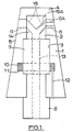
- Figure 1 is a diagrammatic vertical section through a rotary pouring nozzle according to the present invention,
- Figure 2 is a diagrammatic vertical section through a modified form of the pouring nozzle,
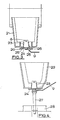
- Figures 3 and 4 show the nozzle fitted to vessels for holding molten metal,
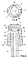
- Figures 5 and 6 show respectively an axial section through and a plan view of a further modified form of the pouring nozzle, and
- Figure 7 is a diagrammatic vertical section through yet another modified form of the pouring nozzle.
- Referring to Figure l of the drawings, the nozzle comprises a
stationary component 1 and arotatable component 2. Both components are made in one-piece from refractory materials. They are interlocked so that whilst therotatable component 2 can be rotated relative to thestationary component 1 they are restrained from relative movement longitudinally and laterally of the rotational axis of the rotatable component, and are inseparable. - The
stationary component 1 is of a frusto-conical shape. It has ahollow interior 3 which opens through the bottom of the component. Thetop 4 of the component is closed. In the tapering surface 5 of the stationary component, near theclosed top 4, are two diametricallyopposed flow apertures 6, of similar diameter, which extend radially into thehollow interior 3. - A major portion of the
rotatable component 2 is contained within thestationary component 1. That portion is cylindrical with an enlarged diameterintermediate part 7. Theinterior 3 of the stationary component is shaped complementally to the portion of the rotatable component which it accommodates. There is a close fitting interconnection between the mating surfaces of theinterior 3 at the rotatable component which permits rotation of the rotatable components but resists all other relative movement between the components, and also resists ingress of metal between the surfaces when the nozzle is in use. The interconnection at the enlargedintermediate part 7 of the rotatable component locks the two components together against separation. A lower end portion of the rotatable component is of square or other suitable non-circular cross-section, or is splined, to form anoperating spigot 8 for engagement by a ringed end of a lever 9, Figures 3 and 4, for turning the component manually. - A porous inert-
gas ring 10 is fitted about the enlargedintermediate part 7 of the rotatable component and is engaged in a locatingannular recess 11 in theinterior 3 of the stationary component. Agas feed pipe 12 extends through the refractory material of the stationary component from its bottom face to thering 10. When the nozzle is in use inert gas, for example argon, is supplied by thegas feed pipe 12 under pressure to thering 10 which releases the gas into the minimal gap between the interfaces of the two components so that gas-film lubrication is provided between the surfaces to prevent the rotatable component from binding or sticking in the stationary component. The gas pressure in the gap also helps to provide further resistance to ingress of metal between the interfaces. - The
ring 10 may be made of a porous refractory material and be formed by a process using a sacrificial reticulated polyurethane foam impregnated with an aqueous slurry of refractory material and a binder. The impregnated foam is dried to remove water and fired to burn off the organic foam to produce a refractory foam replica. Alternatively, the ring may be a solid refractory ring which is rendered gas-permeable by drilling very fine bores to form gas conduits. A similar ring may be formed by the use of organic filaments which may be incorporated in the refractory ring during manufacture and which on subsequent heating are burnt off to leave fine interconnecting conduits. - The rotatable component has an
axial bore 13 which forms a nozzle outlet and extends through the component from the bottom end face of theoperating spigot 8 to anupper end part 14 of the component, above the enlarged diameterintermediate part 7, where it divides into twofeeder entries 15. Thefeeder entries 15 extend outwardly and upwardly and open through the circumferential surface of theupper end part 14 at diametrically opposite positions at the level of theflow apertures 6 in the stationary component. The feeder entries are of similar diameters to the flow apertures with which they can be moved into and out of register by rotation of the rotatable component relative to the stationary component. The division of theaxial bore 13 into thefeeder entries 15 leaves the upper end of the rotatable component completely closed and solid. - An alternative arrangement of the flow apertures in the stationary component and of the feeder entries in the rotatable component is indicated by chain-dot lines in Figure 1. Here one, running, flow aperture 6A is of smaller diameter than the other, starting,
flow aperture 6, and one of the feeder entries, 15A, tapers to a diameter at its mouth, or is for its length of a reduced diameter, corresponding to that of the running flow aperture 6A. Theflow apertures 6, 6A andfeeder entries flow aperture 6 and thefeeder entry 15 of corresponding diameter are brought into register, which is a convenient mode of the nozzle for the start of pouring, and in another angular position the running flow aperture 6A and the taperingfeeder entry 15A are brought into register instead for continuing the pouring. - The two components are made from castable refractory materials containing binders. Suitable binders are those including phosphoric acid and an ethyl-silicate, but other binders may be used if preferred. The components are made by the preferred method described above. Firstly the rotatable component is produced using a polystyrene, or other appropriate high definition, core to define the
axial bore 13 andfeeder entries 15 of the component. After establishing green strength, the refractory component is partially fired at the recognised temperature for the binders to become effective but at a temperature which is not high enough for hysteresis to occur. The core is lost by pyrolysis in the course of the partial firing. The stationary component is then cast in a conic mould around the partially fired rotatable component, after having first applied a varnish to the latter component. Thering 10 is located in the mould prior to casting of the stationary component. The varnish is applied to a uniform thickness over the whole of the surface of theinterior 3 which is to mate with the rotatable component. A non-active refractory, meltable wax or similar, parting compound may alternatively be used but varnish is convenient to use. Destructable inserts, again conveniently made of polystyrene or other such material which are destructable upon firing, are provided to define theflow apertures 6 of the stationary component. Having cast the stationary component, the assembly of the two components is then fully cured and fired in the appropriate cycle of temperature and time, the temperature being higher than that at which the rotatable component had been partially fired. The rotatable component shrinks away from the stationary component in the course of this full firing. The varnish prevents the components from being bonded together during casting of the stationary component and is lost during the full firing of the assembly. - As an alternative the stationary component may be cast first using a destructable core to define its
interior 3 and theflow apertures 6, and the rotatable component then cast inside it. - In the form described and shown in Figure 1 the stationary component is a unitary casting. It may alternatively be of a composite construction. For example, as shown in Figure 2, the stationary component may be made in two parts which connect together about the rotatable component to form the complete component. Here there is an
upper part 16 formed with theflow apertures 6 and having an internally screw-threaded, co-axial,socket 17 in its bottom end, and alower part 18 which contains theporous ring 10 andfeed pipe 12 and has an axial, externally screw-threaded,spigot 19 which screws into thesocket 17 and is surrounded by anannular shoulder 20 at its root. The twoparts hollow interior 3 of the component in which therotatable component 2 is located, its enlargedintermediate part 7 being partially accommodated in each of the two parts. In this construction the rotatable component is slightly modified in that its lower end portion is of the same circular cross-section as the rest of the component below theintermediate part 7 to aid assembly of thering 10 andlower part 18 of the stationary component on the rotatable component. - The upper and
lower parts lower part 18, containing theporous ring 10, is first fitted on to the lower portion of the rotatable component, and then theupper part 16 is slid over the upper portion of the rotatable component and screwed on to thespigot 19 of the lower part. Thespigot 19 is slightly shorter than thesocket 17. Thus when the upper part is screwed fully on to the spigot a small gap remains between the spigot and the inner end of the socket and the bottom face of theupper part 16 is enabled to be seated tightly on theannular shoulder 20 of the lower part. The rotatable component is effectively locked, rotatably, in the stationary component in its operative relationship with that component. - A collar may be fitted to the lower end portion of the rotatable component, below the lower part of the stationary component, for engagement by a lever, or other suitable implement, for turning the rotatable component manually relative to the stationary component.
- As an example only, a refractory material from which either one or both of the components may be made, in the embodiment of Figure 1 or the modification of Figure 2, is a graphitised alumina composition. Typically the composition comprises by weight, 30-60% alumina and 5-30% graphite. This material is known for use in connection with steel and other molten metals.
- One or both of the components described may be made in other ways, as by moulding or a process of isostatic or high pressure linear pressing.
- In the embodiment and modification described the
spigot 8, or the collar, may be adapted for turning the rotatable component by power-driven means, if required. For example, the spigot or collar may be connected for turning by a hydraulically-operated piston, or there may be a mechanical drive such as a rack and pinion in which the spigot is engaged with, or the collar may be, the pinion. - For use the nozzle is mounted in the bottom of a vessel which is to hold molten metal for pouring. The vessel may, for example, be a
foundry type ladle 21 as shown in Figure 3, or atundish 22 as shown in Figure 4 for use in billet or bloom casting. For each of these applications the stationary component of the nozzle is engaged and sealed in a complementary frusto-conical opening 23 in the bottom of the vessel, and is secured by a retainingring 24 held fast to the underside of the exterior of the vessel bypegs 25 fixed to the vessel andwedges 26. As installed, the upper end of the stationary component projects into the vessel to an extent such that theflow apertures 6 are above the level of the lining of the vessel. - The stationary component may be readily disconnected from the vessel for repair or replacement of the nozzle.
- The lever 9 for turning the rotatable component is applied to the component below the retaining
ring 24. By means of the lever 9 the rotatable component can be turned relative to the stationary component between a pouring position in which thefeeder entries 15 are in register with theflow apertures 6 and metal can flow out of the vessel through the nozzle outlet bore 13, and a closed position in which the feeder entries are out of register with the flow apertures. Upon being turned to the closed position, all residual metal in the feeder entries and nozzle outlet of the rotatable component drain out of the nozzle. Thus the nozzle is self-draining which is particularly advantageous because there is no problem of metal solidifying in the nozzle, and hence the periods for which the nozzle can be left closed between pourings are not limited. Pouring will commence immediately upon turning the rotatable component to the pouring position. - As shown in Figure 4 a submerged
entry shroud 27 may be fitted to the rotatable component, for example, for feeding metal into a billet orbloom mould 28 or for shielded casting of steel in a continuous casting process. The submergedentry shroud 27 rotates with the rotatable component. It may be straight, as shown, or bifurcated. - Two further modified forms of the rotary pouring nozzle are illustrated by Figures 5, 6 and 7 of the accompanying drawings and will now be described. Parts corresponding to those of the embodiment described are identified by the same reference numerals. In each of these modified forms the
stationary component 1 and therotatable component 2 are each made in one piece of refractory material. They may be made by the method described above. - A particular feature of the modified form of the nozzle illustrated by Figures 5 and 6 is that the
stationary component 1 has an oval external circumferential shape. For mounting the nozzle for use the stationary component is located and sealed in an opening of complementary oval shape in the bottom of the vessel to which the nozzle is fitted. Thus the interengagement between the stationary component and the opening prevents rotatation of the stationary component with the rotatable component relative to the vessel. - In this modified form of the nozzle a
lower portion 29 of the stationary component is of a constant cross-section, and anupper portion 30 of the component containing theflow apertures 6 tapers upwardly and merges into theclosed top 4 of the component at a well-rounded radius. There are two diametricallyopposed flow apertures 6, which have an outward flare. Therotatable component 2 has acylindrical stem portion 31 and an enlarged, upwardly tapering,head portion 32 accommodated in the complementally shapedinterior 3 of the stationary component. The taper of thehead portion 32 similarly merges into the top of the head portion at a well-rounded radius. As before, the close fitting interconnection between the mating surfaces of theinterior 3 of the stationary component at the stem and head portion of the rotatable component permits rotation of the rotatable component in the stationary component but resists other relative movement between the components. The nozzle outlet in the rotatable component is again formed by anaxial bore 13 from the upper end of which two oppositely directedfeeder entries 15, of similar diameter of the inner ends of theflow apertures 6, extend outwardly and slightly upwardly to the tapering circumferential surface of thehead portion 32 at the level of the inner ends of the flow apertures. A lower part of thestem portion 31 projects out of the bottom of the stationary component to form theoperating spigot 8 of the rotatable component, which may be splined or otherwise suitably formed for engagement by a ringed end of a lever or by power-driven means. - The
stationary component 1 of the further modified form of the nozzle illustrated by Figure 7 is of a double frusto-conical external shape tapering towards its opposite ends from a short cylindricalcentral portion 33. A lower frusto-conical portion 34 locates in and is sealed in anopening 23 of complementary shape in the bottom of the vessel to which the nozzle is fitted for use. The location is made from inside the vessel, which is convenient when the vessel is a tundish or small ladle. An upper frusto-conical portion 35 contains theflow apertures 6 of which again there are two, being diametrically opposed and outwardly flared. In this modification therotatable component 2 has an upwardly taperinghead portion 36 within the upper frusto-conical portion 34 of the stationary component, and astem portion 37 which for the greater part of its length from the head portion flares downwardly and terminates in a downwardly tapering frusto-conicallower end 38 spaced below the bottom of the stationary component. Adjacent thestem portion 37 thehead portion 36 has a narrow bevelledannular undersurface 39. Theinterior 3 of the stationary component is shaped complementally to thehead portion 36, thebevelled undersurface 39 and the adjoining part of thestem portion 37 of the rotatable component to permit rotation of the latter but no other relative movement between the two components. The nozzle outlet in the rotatable component is formed, as before, by anaxial bore 13 extending down from the head portion, through the stem portion and thelower end 38 and having two oppositely directedfeeder entries 15, of similar diameter to the inner ends of theflow apertures 6, extending to the tapering circumferential surface of the head portion at the level of the flow apertures. That part of thestem portion 37 projecting below the stationary component forms thespigot 8 of the rotatable component for turning the component. At thespigot 8, in the region where the flared part of thestem portion 37 and the frusto-conicallower end 38 meet,splines 40 are formed for engagement by a ringed end of a lever or by power-driven means. - As shown in Figure 7, the
lower end 38 of thestem portion 37 of the rotatable component can co-operate with a submergedentry shroud 27. - Although the lower and upper externally tapering
portions - The stationary and rotatable components may be interlocked in other ways from those described and illustrated. One or the other may be formed with an annular groove or recess with which a keying projection or projections on the other engage to allow the rotatable component to rotate in the stationary component and yet restrain other relative movement between the components. For example, an annular groove may be formed in the circumference of the rotatable component, and angularly spaced orifices may be formed in the stationary component opposite the groove into which a castable refractory is injected to enter into the groove and be fixed to the stationary component in the orifices, thereby locking the rotatable component in the stationary component. Prior to injecting the castable refractory the groove is coated with varnish or other suitable parting agent to prevent the refractory from bonding to the rotatable component. Another possibility is to form a groove in the circumference of the rotatable components and locate pre-formed segments, which may be made of refractory, in an adjacent recess or recesses in the stationary component to project into the groove. The segments may be urged into the groove by spring loading, for example provided by helical compression springs held against outer circumferential surfaces of the segments in the recess or recesses by a circumferential band or annulus fitted around the stationary component opposite the recess or recesses.
Claims (15)
Priority Applications (1)
| Application Number | Priority Date | Filing Date | Title |
|---|---|---|---|
| AT88308787T ATE85249T1 (en) | 1987-10-01 | 1988-09-22 | ROTARY CASTING NOZZLE FOR A VESSEL FOR STORING MOLTEN METAL. |
Applications Claiming Priority (2)
| Application Number | Priority Date | Filing Date | Title |
|---|---|---|---|
| GB8723059 | 1987-10-01 | ||
| GB878723059A GB8723059D0 (en) | 1987-10-01 | 1987-10-01 | Rotary pouring nozzle |
Publications (3)
| Publication Number | Publication Date |
|---|---|
| EP0310296A2 true EP0310296A2 (en) | 1989-04-05 |
| EP0310296A3 EP0310296A3 (en) | 1990-05-16 |
| EP0310296B1 EP0310296B1 (en) | 1993-02-03 |
Family
ID=10624645
Family Applications (1)
| Application Number | Title | Priority Date | Filing Date |
|---|---|---|---|
| EP88308787A Expired - Lifetime EP0310296B1 (en) | 1987-10-01 | 1988-09-22 | Rotary pouring nozzle for a vessel for holding molten metal |
Country Status (11)
| Country | Link |
|---|---|
| US (1) | US4840295A (en) |
| EP (1) | EP0310296B1 (en) |
| JP (1) | JPH01107952A (en) |
| KR (1) | KR890006324A (en) |
| CN (1) | CN1041552A (en) |
| AT (1) | ATE85249T1 (en) |
| AU (1) | AU2270188A (en) |
| BR (1) | BR8805043A (en) |
| DE (1) | DE3878125T2 (en) |
| GB (1) | GB8723059D0 (en) |
| ZA (1) | ZA887363B (en) |
Cited By (4)
| Publication number | Priority date | Publication date | Assignee | Title |
|---|---|---|---|---|
| EP0423449A2 (en) * | 1989-10-17 | 1991-04-24 | Didier-Werke Ag | Shut-off and/or control element for a metallurgical container |
| EP0474863A1 (en) * | 1989-06-01 | 1992-03-18 | Shinagawa Refractories Co., Ltd. | Apparatus for controlling flow rate of molten metal |
| WO1992012815A1 (en) * | 1991-01-18 | 1992-08-06 | Foseco International Limited | Vessel outlet |
| GB2226263B (en) * | 1988-12-22 | 1992-11-04 | Steel Castings Res | Valve for vessel outlet |
Families Citing this family (10)
| Publication number | Priority date | Publication date | Assignee | Title |
|---|---|---|---|---|
| DE3731600A1 (en) * | 1987-09-19 | 1989-04-06 | Didier Werke Ag | TURNTABLE CLOSURE FOR A METALURIGAN TUBE AND ROTOR AND / OR STATOR FOR SUCH A TURNOVER |
| CH676811A5 (en) * | 1988-09-29 | 1991-03-15 | Stopinc Ag | |
| DE4001095A1 (en) * | 1990-01-17 | 1991-07-18 | Didier Werke Ag | LOCKING DEVICE FOR A MELTING VESSEL |
| CA2084845A1 (en) * | 1992-12-08 | 1994-06-09 | Roderick I.L. Guthrie | Flow control device for the suppression of vortices |
| US5916471A (en) * | 1998-11-10 | 1999-06-29 | North American Refractories Co. | Rotary socket taphole assembly |
| FI120385B (en) * | 2007-07-06 | 2009-10-15 | Indref Oy | Sealing mechanism for metering of metal melt and method for manufacturing a sealing mechanism |
| JP2010188398A (en) * | 2009-02-19 | 2010-09-02 | Kurosaki Harima Corp | Sliding nozzle apparatus |
| CN108247033B (en) * | 2018-01-17 | 2020-07-21 | 武汉科技大学 | Rotational flow water feeding port for continuous casting tundish |
| JP7133948B2 (en) * | 2018-03-06 | 2022-09-09 | 黒崎播磨株式会社 | Tuyere installation structure |
| CN109226734B (en) * | 2018-11-19 | 2023-08-25 | 泰州市旺鑫耐火材料有限公司 | Automatic flow control device for tundish nozzle |
Citations (6)
| Publication number | Priority date | Publication date | Assignee | Title |
|---|---|---|---|---|
| US3651998A (en) * | 1970-09-23 | 1972-03-28 | Metallurg Exoproducts Corp | Nozzle for a pouring ladle |
| GB1276625A (en) * | 1969-02-28 | 1972-06-07 | Martin Neitzel | Improvements in or relating to rotary pouring valves for vessels containing molten metal |
| DE2226173A1 (en) * | 1971-06-09 | 1972-12-21 | H Bieri | Closing device for outlet openings of pouring ladles |
| DE2836813A1 (en) * | 1977-09-16 | 1979-03-29 | Voest Ag | ROTARY SLIDER LATCH FOR VESSELS WITH A FIRE-RESISTANT LINING |
| DE3424254C1 (en) * | 1984-05-23 | 1985-07-11 | Stopinc Ag, Baar | Rotary slide lock |
| EP0196847A2 (en) * | 1985-03-26 | 1986-10-08 | British Steel plc | Improvements in or relating to outlet valves for melt containing vessels |
Family Cites Families (2)
| Publication number | Priority date | Publication date | Assignee | Title |
|---|---|---|---|---|
| US2698630A (en) * | 1951-04-19 | 1955-01-04 | Gen Motors Corp | Valve |
| NL162579B (en) * | 1969-02-22 | Didier Werke Ag | DEVICE FOR REGULATING AND CLOSING THE DISCHARGE OF MOLTEN METAL THROUGH A BOTTOM OPENING FROM A RESERVOIR. |
-
1987
- 1987-10-01 GB GB878723059A patent/GB8723059D0/en active Pending
-
1988
- 1988-09-19 US US07/246,313 patent/US4840295A/en not_active Expired - Fee Related
- 1988-09-22 EP EP88308787A patent/EP0310296B1/en not_active Expired - Lifetime
- 1988-09-22 AT AT88308787T patent/ATE85249T1/en not_active IP Right Cessation
- 1988-09-22 DE DE8888308787T patent/DE3878125T2/en not_active Expired - Fee Related
- 1988-09-22 AU AU22701/88A patent/AU2270188A/en not_active Abandoned
- 1988-09-28 JP JP63243732A patent/JPH01107952A/en active Pending
- 1988-09-30 ZA ZA887363A patent/ZA887363B/en unknown
- 1988-09-30 BR BR8805043A patent/BR8805043A/en unknown
- 1988-10-01 CN CN88109092A patent/CN1041552A/en active Pending
- 1988-10-04 KR KR1019880012946A patent/KR890006324A/en not_active Application Discontinuation
Patent Citations (6)
| Publication number | Priority date | Publication date | Assignee | Title |
|---|---|---|---|---|
| GB1276625A (en) * | 1969-02-28 | 1972-06-07 | Martin Neitzel | Improvements in or relating to rotary pouring valves for vessels containing molten metal |
| US3651998A (en) * | 1970-09-23 | 1972-03-28 | Metallurg Exoproducts Corp | Nozzle for a pouring ladle |
| DE2226173A1 (en) * | 1971-06-09 | 1972-12-21 | H Bieri | Closing device for outlet openings of pouring ladles |
| DE2836813A1 (en) * | 1977-09-16 | 1979-03-29 | Voest Ag | ROTARY SLIDER LATCH FOR VESSELS WITH A FIRE-RESISTANT LINING |
| DE3424254C1 (en) * | 1984-05-23 | 1985-07-11 | Stopinc Ag, Baar | Rotary slide lock |
| EP0196847A2 (en) * | 1985-03-26 | 1986-10-08 | British Steel plc | Improvements in or relating to outlet valves for melt containing vessels |
Cited By (9)
| Publication number | Priority date | Publication date | Assignee | Title |
|---|---|---|---|---|
| GB2226263B (en) * | 1988-12-22 | 1992-11-04 | Steel Castings Res | Valve for vessel outlet |
| EP0474863A1 (en) * | 1989-06-01 | 1992-03-18 | Shinagawa Refractories Co., Ltd. | Apparatus for controlling flow rate of molten metal |
| EP0474863A4 (en) * | 1989-06-01 | 1992-05-06 | Shinagawa Refractories Co., Ltd. | Apparatus for controlling flow rate of molten metal |
| EP0423449A2 (en) * | 1989-10-17 | 1991-04-24 | Didier-Werke Ag | Shut-off and/or control element for a metallurgical container |
| EP0423449A3 (en) * | 1989-10-17 | 1991-12-04 | Didier-Werke Ag | Shut-off and/or control element for a metallurgical container |
| WO1992012815A1 (en) * | 1991-01-18 | 1992-08-06 | Foseco International Limited | Vessel outlet |
| AU653987B2 (en) * | 1991-01-18 | 1994-10-20 | Foseco International Limited | Vessel outlet |
| ES2085200A2 (en) * | 1991-01-18 | 1996-05-16 | Foseco Int | Vessel outlet |
| US5603859A (en) * | 1991-01-18 | 1997-02-18 | Foseco International Limited | Vessel outlet |
Also Published As
| Publication number | Publication date |
|---|---|
| KR890006324A (en) | 1989-06-13 |
| CN1041552A (en) | 1990-04-25 |
| JPH01107952A (en) | 1989-04-25 |
| BR8805043A (en) | 1989-05-09 |
| ATE85249T1 (en) | 1993-02-15 |
| GB8723059D0 (en) | 1987-11-04 |
| AU2270188A (en) | 1989-04-06 |
| EP0310296A3 (en) | 1990-05-16 |
| EP0310296B1 (en) | 1993-02-03 |
| DE3878125D1 (en) | 1993-03-18 |
| ZA887363B (en) | 1989-06-28 |
| US4840295A (en) | 1989-06-20 |
| DE3878125T2 (en) | 1993-05-27 |
Similar Documents
| Publication | Publication Date | Title |
|---|---|---|
| EP0310296B1 (en) | Rotary pouring nozzle for a vessel for holding molten metal | |
| US4946083A (en) | One-piece stopper rod | |
| SE503653C2 (en) | Molded metal molding with downflow socket with ceramic filter | |
| GB1575601A (en) | Refractory structures for outlet valves for metallurgical vessels | |
| US7464744B2 (en) | Shot sleeve insert and method of retarding heat erosion within a shot sleeve bore | |
| EP0022373B2 (en) | Continuous casting apparatus | |
| EP0281267B1 (en) | Devices and apparatus for injecting gas into high temperature liquids, e.g. molten metals | |
| JPH07308757A (en) | Sliding nozzle plate | |
| US5819838A (en) | Method of manufacturing a bimetallic grinding wheel | |
| US4365731A (en) | Refractory structures | |
| CA1340564C (en) | Refractory stator/rotor unit for a valve at the outlet of a vessel containing metal melt | |
| US5866022A (en) | Refractory pour tube with cast plate | |
| SU1722220A3 (en) | Cut-off or control member for discharging liquid metal from metallurgical vessel | |
| JP3426177B2 (en) | Casting stopper | |
| US4555094A (en) | Process for the repair of slide plates | |
| GB2150868A (en) | Porous plug assemblies for molten metal vessels e.g. ladles | |
| EP0509699A1 (en) | Gas permeable well nozzle | |
| EP0882534B1 (en) | Apparatus and use of the apparatus for producing a cylinder block of an internal combustion engine | |
| US3980271A (en) | Pouring of molten metals | |
| US4330107A (en) | Teapot ladle and method of use | |
| CA2567598C (en) | Sliding plate | |
| JPH09141405A (en) | Tundish stopper for continuous casting | |
| JP3272726B2 (en) | Apparatus for connecting a stopper rod for a metallurgical vessel to a lifting apparatus, stopper rod adapted to the apparatus, and method of manufacturing the apparatus | |
| CA2433595A1 (en) | Well block for metallurgical vessel | |
| JPH0235629B2 (en) |
Legal Events
| Date | Code | Title | Description |
|---|---|---|---|
| PUAI | Public reference made under article 153(3) epc to a published international application that has entered the european phase |
Free format text: ORIGINAL CODE: 0009012 |
|
| AK | Designated contracting states |
Kind code of ref document: A2 Designated state(s): AT BE CH DE ES FR GB GR IT LI LU NL SE |
|
| PUAL | Search report despatched |
Free format text: ORIGINAL CODE: 0009013 |
|
| AK | Designated contracting states |
Kind code of ref document: A3 Designated state(s): AT BE CH DE ES FR GB GR IT LI LU NL SE |
|
| 17P | Request for examination filed |
Effective date: 19900704 |
|
| 17Q | First examination report despatched |
Effective date: 19911115 |
|
| GRAA | (expected) grant |
Free format text: ORIGINAL CODE: 0009210 |
|
| AK | Designated contracting states |
Kind code of ref document: B1 Designated state(s): AT BE CH DE ES FR GB GR IT LI LU NL SE |
|
| PG25 | Lapsed in a contracting state [announced via postgrant information from national office to epo] |
Ref country code: IT Free format text: LAPSE BECAUSE OF FAILURE TO SUBMIT A TRANSLATION OF THE DESCRIPTION OR TO PAY THE FEE WITHIN THE PRE;WARNING: LAPSES OF ITALIAN PATENTS WITH EFFECTIVE DATE BEFORE 2007 MAY HAVE OCCURRED AT ANY TIME BEFORE 2007. THE CORRECT EFFECTIVE DATE MAY BE DIFFERENT FROM THE ONE RECORDED.SCRIBED TIME-LIMIT Effective date: 19930203 Ref country code: GR Free format text: LAPSE BECAUSE OF FAILURE TO SUBMIT A TRANSLATION OF THE DESCRIPTION OR TO PAY THE FEE WITHIN THE PRESCRIBED TIME-LIMIT Effective date: 19930203 Ref country code: SE Effective date: 19930203 Ref country code: NL Effective date: 19930203 Ref country code: LI Effective date: 19930203 Ref country code: ES Free format text: THE PATENT HAS BEEN ANNULLED BY A DECISION OF A NATIONAL AUTHORITY Effective date: 19930203 Ref country code: AT Effective date: 19930203 Ref country code: CH Effective date: 19930203 |
|
| REF | Corresponds to: |
Ref document number: 85249 Country of ref document: AT Date of ref document: 19930215 Kind code of ref document: T |
|
| REF | Corresponds to: |
Ref document number: 3878125 Country of ref document: DE Date of ref document: 19930318 |
|
| REG | Reference to a national code |
Ref country code: CH Ref legal event code: PL |
|
| ET | Fr: translation filed | ||
| NLV1 | Nl: lapsed or annulled due to failure to fulfill the requirements of art. 29p and 29m of the patents act | ||
| PLBI | Opposition filed |
Free format text: ORIGINAL CODE: 0009260 |
|
| PLBI | Opposition filed |
Free format text: ORIGINAL CODE: 0009260 |
|
| 26 | Opposition filed |
Opponent name: DIDIER-WERKE AG Effective date: 19931102 |
|
| 26 | Opposition filed |
Opponent name: VEITSCH-RADEX AKTIENGESELLSCHAFT FUER FEUERFESTE E Effective date: 19931103 Opponent name: DIDIER-WERKE AG Effective date: 19931102 |
|
| EPTA | Lu: last paid annual fee | ||
| PLAB | Opposition data, opponent's data or that of the opponent's representative modified |
Free format text: ORIGINAL CODE: 0009299OPPO |
|
| R26 | Opposition filed (corrected) |
Opponent name: DIDIER-WERKE AG * 931103 VEITSCH-RADEX AKTIENGESEL Effective date: 19931102 |
|
| PGFP | Annual fee paid to national office [announced via postgrant information from national office to epo] |
Ref country code: LU Payment date: 19950801 Year of fee payment: 8 |
|
| PGFP | Annual fee paid to national office [announced via postgrant information from national office to epo] |
Ref country code: FR Payment date: 19950803 Year of fee payment: 8 |
|
| PGFP | Annual fee paid to national office [announced via postgrant information from national office to epo] |
Ref country code: GB Payment date: 19950815 Year of fee payment: 8 |
|
| PGFP | Annual fee paid to national office [announced via postgrant information from national office to epo] |
Ref country code: DE Payment date: 19950823 Year of fee payment: 8 |
|
| PGFP | Annual fee paid to national office [announced via postgrant information from national office to epo] |
Ref country code: BE Payment date: 19950824 Year of fee payment: 8 |
|
| PG25 | Lapsed in a contracting state [announced via postgrant information from national office to epo] |
Ref country code: LU Free format text: LAPSE BECAUSE OF NON-PAYMENT OF DUE FEES Effective date: 19960922 Ref country code: GB Effective date: 19960922 |
|
| PG25 | Lapsed in a contracting state [announced via postgrant information from national office to epo] |
Ref country code: FR Effective date: 19960930 Ref country code: BE Effective date: 19960930 |
|
| APAC | Appeal dossier modified |
Free format text: ORIGINAL CODE: EPIDOS NOAPO |
|
| APAC | Appeal dossier modified |
Free format text: ORIGINAL CODE: EPIDOS NOAPO |
|
| BERE | Be: lapsed |
Owner name: FOSECO INTERNATIONAL LTD Effective date: 19960930 |
|
| GBPC | Gb: european patent ceased through non-payment of renewal fee |
Effective date: 19960922 |
|
| PG25 | Lapsed in a contracting state [announced via postgrant information from national office to epo] |
Ref country code: DE Effective date: 19970603 |
|
| REG | Reference to a national code |
Ref country code: FR Ref legal event code: ST |
|
| APAC | Appeal dossier modified |
Free format text: ORIGINAL CODE: EPIDOS NOAPO |
|
| PLBL | Opposition procedure terminated |
Free format text: ORIGINAL CODE: EPIDOS OPPC |
|
| REG | Reference to a national code |
Ref country code: FR Ref legal event code: ST |
|
| PLBL | Opposition procedure terminated |
Free format text: ORIGINAL CODE: EPIDOS OPPC |
|
| PLBL | Opposition procedure terminated |
Free format text: ORIGINAL CODE: EPIDOS OPPC |
|
| PLBM | Termination of opposition procedure: date of legal effect published |
Free format text: ORIGINAL CODE: 0009276 |
|
| D27C | Opposition proceedings terminated (deleted) | ||
| PLAD | Information related to termination of opposition procedure modified |
Free format text: ORIGINAL CODE: 0009299OPPC |
|
| STAA | Information on the status of an ep patent application or granted ep patent |
Free format text: STATUS: OPPOSITION PROCEDURE CLOSED |
|
| R27C | Opposition proceedings terminated (corrected) |
Effective date: 19970929 |
|
| APAH | Appeal reference modified |
Free format text: ORIGINAL CODE: EPIDOSCREFNO |