EP0310253A2 - Procédé pour écarter la dispersion Doppler de phase des données sismiques - Google Patents
Procédé pour écarter la dispersion Doppler de phase des données sismiques Download PDFInfo
- Publication number
- EP0310253A2 EP0310253A2 EP88308192A EP88308192A EP0310253A2 EP 0310253 A2 EP0310253 A2 EP 0310253A2 EP 88308192 A EP88308192 A EP 88308192A EP 88308192 A EP88308192 A EP 88308192A EP 0310253 A2 EP0310253 A2 EP 0310253A2
- Authority
- EP
- European Patent Office
- Prior art keywords
- frequency
- seismic
- operator
- domain
- dip
- Prior art date
- Legal status (The legal status is an assumption and is not a legal conclusion. Google has not performed a legal analysis and makes no representation as to the accuracy of the status listed.)
- Withdrawn
Links
Images


Classifications
-
- G—PHYSICS
- G01—MEASURING; TESTING
- G01V—GEOPHYSICS; GRAVITATIONAL MEASUREMENTS; DETECTING MASSES OR OBJECTS; TAGS
- G01V1/00—Seismology; Seismic or acoustic prospecting or detecting
- G01V1/38—Seismology; Seismic or acoustic prospecting or detecting specially adapted for water-covered areas
- G01V1/3808—Seismic data acquisition, e.g. survey design
-
- G—PHYSICS
- G01—MEASURING; TESTING
- G01V—GEOPHYSICS; GRAVITATIONAL MEASUREMENTS; DETECTING MASSES OR OBJECTS; TAGS
- G01V1/00—Seismology; Seismic or acoustic prospecting or detecting
- G01V1/28—Processing seismic data, e.g. analysis, for interpretation, for correction
- G01V1/36—Effecting static or dynamic corrections on records, e.g. correcting spread; Correlating seismic signals; Eliminating effects of unwanted energy
- G01V1/364—Seismic filtering
-
- Y—GENERAL TAGGING OF NEW TECHNOLOGICAL DEVELOPMENTS; GENERAL TAGGING OF CROSS-SECTIONAL TECHNOLOGIES SPANNING OVER SEVERAL SECTIONS OF THE IPC; TECHNICAL SUBJECTS COVERED BY FORMER USPC CROSS-REFERENCE ART COLLECTIONS [XRACs] AND DIGESTS
- Y10—TECHNICAL SUBJECTS COVERED BY FORMER USPC
- Y10S—TECHNICAL SUBJECTS COVERED BY FORMER USPC CROSS-REFERENCE ART COLLECTIONS [XRACs] AND DIGESTS
- Y10S367/00—Communications, electrical: acoustic wave systems and devices
- Y10S367/904—Doppler compensation systems
Definitions
- the invention relates to the field of marine seismic exploration.
- marine seismic exploration has been performed for the most part with the use of impulsive sources.
- impulsive sources For a number of reasons, however, interest in marine vibrators has increased.
- vibrator data are less sensitive than are data acquired with impulsive sources to many kinds of noise bursts, including shots from other crews, sounds from shipping lanes and drilling rigs, and activities of marine animals.
- Two vibrating sources can be run simultaneously with orthogonal sweep functions and data from two adjacent seismic lines acquired simultaneously with a single receiver cable, without having to compromise shotpoint spacing by alternately firing two sources. Since the output of a vibrator is spread over a relatively long time interval, the peak output level of the source is much lower than that of an impulsive source having comparable strength, which reduces possible impact on the environment.
- the invention is a method of reducing phase distortion in a detected seismic signal resulting from Doppler shifting of the transmitted signal.
- An operator is convolved with the seismic data to reduce the distortion
- the operator may be adapted for the particular transmitted signal and boat speed.
- the operator is normally determined in the frequency-wave number domain.
- the seismic data may be transformed to the frequency-wave number domain for performing the convolution.
- the transformed data may then be transformed back to the time-space domain.
- the determined operator may be transformed to the time-space domain and the convolution performed in that domain.
- Doppler shift is the term normally used to designate the difference in frequency between a received and transmitted signal resulting from movement of the transmitter and/or the receiver during the signal transmission or reception.
- Doppler shifting will occur if either the source or detectors are moving during transmission of the seismic signal.
- dipping subsurface reflecting interfaces will create a Doppler shift even though the seismic source and receiver are both towed by the same boat and have zero velocity with respect to each other. This phenomena is illustrated in FIG. 1.
- Most marine seismic exploration is performed by towing the source and detectors behind a boat at a constant velocity and the invention will be described herein primarily as it applies to such operations.
- the term vibrator or vibratory source is intended to refer to sources which emit seismic signals having a selected frequency content over a period of time which will normally be several seconds. These signals may be sinusoidal, or they may be substantially square-wave signals, or they may comprise other form of shaped-pulse signals.
- the seismic signals emitted by these sources are commonly referred to as sweeps, since the fundamental frequency of the signal will normally begin at a selected frequency and "sweep" from that beginning frequency to a different ending frequency.
- the change in frequency with time may be linear or nonlinear. In some situations, it may be desirable to transmit a single frequency sinusoidal, square-wave, or shaped-pulse signals, which are intended to be included within the term "swept-frequency" as used herein.
- FIG. represents a marine seismic cable 3 and a marine seismic source 4 being pulled through a body of water 2 by a seismic vessel.
- FIG. 1 represents the source generating a signal as the source is towed from a first position 4a to a second position 4b. From position 4a, the emitted seismic signal is shown travelling along ray paths 6a and 8a to subsurface reflecting interfaces 10 and 12 respectively. From position 4b the signal will travel along ray paths 6b and 8b. It can be seen that, for a reflection from an interface lying parallel to the earth's surface, the length of the path travelled by the seismic signal along paths 6a and 6b will be the same, hence, there will be no Doppler effect.
- ray path 8b is longer than ray path 8a, with the result that the frequency of the signal detected by the receiver on the cable as the source moves from position 4a to 4b will-be lower than the frequency of the signal transmitted by the source.
- a dip of the reflecting interface in the opposite direction would, of course, result in an increased detected frequency.
- V b the maximum Doppler factor is V b /V p , in which V b represents the speed of the source or detector, whichever is moving.
- seismic ships typically maintain a speed of about 5 knots (2.57 meters/second). Since Vp is about 1500 meters/second, the largest Doppler factor that is likely to be encountered in recording marine data is about 0.0034. If a marine seismic vibrator generates a signal which sweeps from 10 Hz to 60 Hz, then frequency shifts of between 0.034 Hz and 0.204 Hz between the transmitted and received signals could be observed at the frequency extremes of the sweep.
- FIGS. 2a, 2b and 2c illustrate the effect of the Doppler frequency shift on seismic data.
- FIG. 2a shows a transmitted, or pilot, seismic signal which sweeps from a first frequency, f 1 , to a second frequency, f 2 , over a period of 10 seconds.
- the distance traveled between the source and receiver remains constant, and the received signal will have the same form as the transmitted signal.
- the reception will be delayed by the travel time from source to receiver, but this delay time will be constant over the period of the sweep.
- FIG. 2b shows the same pilot sweep and a representation of the alteration of the received signal resulting from a progressive shortening of transmission path length during the time period over which the signal is transmitted and received. Because of the shortening of the transmission path, the transmission time between the source and receiver, as well as the frequency of the received signal, will be shifted.
- Equation 3 For a pilot signal which sweeps from 10 to 60 Hz and a Doppler factor of 0.0034, the phase shift at 60 Hz calculated from Equation 3 is 880°. Even one- tenth this much phase shift would visibly alter the character of reflection events.
- a model was generated in which a dipping bed is treated as a sequence of closely-spaced point diffractors.
- the response of each point diffractor was computed by simulating the "towing" of a source and receiver across each point diffractor with the offset between the source and receiver being kept constant.
- Correlating the simulated received signals with the pilot sweep produces a gather which models the response of the point diffractor at a particular source-receiver offset. Summing the responses of all the individual point diffractors in a segment produces the constant-offset response of the dipping segment.
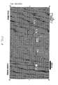
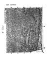
- FIGS. 3 and 4 show the simulated results for reflecting segments of a number of different dips.
- FIG. 3 is modeled with zero source and receiver velocity and zero offset between the source and receiver.
- FIG. 4 is modeled with zero-offset between source and receiver but with the source and receiver being towed through the water at a speed of 5 knots (2.57 meters/second).
- the data for FIGS. 3 and 4 were generated by calculating the received signal waveform and correlating this received waveform with the transmitted waveform.
- the top of each segment in the model is at a depth of 500 meters, with the velocity of the seismic signal assumed to be 1500 meters/second. Each segment spans a horizontal distance of 200 meters.
- phase dispersion caused by the Doppler effect can be seen by comparing the wavelets in FIG. 4 to those in FIG. 3. For 0' dip there is no dispersion. As is clearly visible from FIG.4 as the dip angle increases the dispersion increases accordingly.
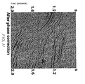
- FIG. 5 shows the phase dispersion more quantitatively.
- FIG. 5 shows a plot of phase as a function of frequency and dip angle of the reflecting interface.
- FIG. 5 was generated by selecting particular traces from FIG. 3, finding the phase only inverses of the wavelets in those traces, convolving the inverses with the corresponding Doppler-shifted traces from FIG. 4, and then transforming the results into the frequency domain.
- FIG. 5 is in agreement with Equation 3, showing an increase in phase dispersion with frequency and dip angle.
- phase dispersion is removed from the seismic data by convolving this operator with the data.
- This correction method requires knowledge of the Doppler factor.
- the Doppler factor In order for the method to be applied to a set of data, the Doppler factor must be determinable for every reflection event in the data set.
- the Doppler factor depends only on the direction of the transmitted and received signal in the water layer, but is independent of any variations in those directions which may occur in the subsurface, and that the Doppler factor is a function only of the boat speed and the time dip of the seismic signal, that is: in which ⁇ t ⁇ y is the time di p
- phase dispersion may be conveniently generated in the k-u) (wave number-frequency) domain.
- k-u wave number-frequency
- a constant offset section is a hodgepodge of events.
- each area of a seismic data section corresponds to a unique frequency and dip.
- Phase dispersion may, therefore, be corrected by:
- the operator that will correct a particular set of seismic data for the Doppler shift may be derived by the following procedure implemented on a digital computer.
- Computer programs to implement the steps specified herein may be drafted by those of ordinary skill in the art, and will not be included herein.
- f a is generally known as the "spatial-alias frequency".
- the operator coefficients are computed from the complex conjugate computed in step 7 for the selected values of ⁇ .
- the location in the k- ⁇ grid to which the computed coefficients are to be assigned are determined by computing, from Equation 11, the values of k corresponding to the selected values of w for the selected dip.
- the derived filter may be transformed to the time-space domain, and then convolved with the seismic data in the time space domain as follows:
- phase correcting filter is changed to the time-space domain or the data are changed to the frequency-wave number domain in order to perform the data correction, the processess are equivalent.
- the Doppler factor is a function only of boat speed, V b , and reflection event time dip, ⁇ t/ ⁇ y.
- the Doppler effect does not depend explicitly on the amount of the offset or on the seismic velocity. Only one two-dimensional (2D) k-m phase correcting operator per sweep type and boat speed is needed to correct a constant source-receiver offset section. For different offsets within the same data section, however, the same events will receive different phase treatments, so that for an exact correlation of phase distortion, a data set is processed before stacking, and prior to any other processing steps which alter the dip of reflection events.
- the Doppler phase dispersion may be corrected approximately by applying the k- ⁇ phase operator to data which have been corrected for normal moveout and stacked. Only reflections from shallow events at far offsets will not be substantially corrected, and those portions of a marine data set are normally muted out. Surveys that have particularly shallow target horizons or that will be processed to extract amplitude-versus-offset information may preferably be corrected for phase dispersion prior to stacking.
- dipping reflections should be examined to determine if any of them are spatially aliased.
- Spatially aliased means that the data are sampled too coarsely in the offset (i.e., space) direction. Higher frequencies in spatially aliased events appear, because of the sampling, to have dips different from their true dips. Such events will not receive a proper phase correction because they will not map into the expected location in the k- " , domain.
- An aliasing problem may be remedied either by interpolating the data set to a finer trace spacing, or by applying a low-pass filter to the data set at some stage in processing.
- FIG. 7 is a phase-corrected version of FIG. 4. A comparison shows that application of the phase- correction operator has removed the phase dispersion caused by the Doppler effect. It has also been verified that the same operator works equally well when applied to a non-zero-offset section as to a zero offset section.
- FIG. 8 shows a stack before application of the Doppler phase correction
- FIG. 9 shows the stack after application of the correction, for one of those lines, from the South Pass area offshore Louisiana.
- the line was shot with a 10 second sweep, going from 7.5 Hz to 100 Hz with a 6dB/octave slope before correlation.
- the boat speed was 4.7 knots (2.42m/sec) from left to right in the two figures.
- the data processing which was done at a 4-millisecond sampling interval, including trace-by-trace spiking deconvolution and dip-moveout before stack, and time-variant spectral whitening, automatic gain compensation, and time-variant bandpass filtering after stack.
- FIGS. 8 and 9 show that the Doppler effect has caused an upward phase dispersion in dipping reflection events for which the boat motion was up-dip, and a downward phase dispersion in dipping events for which the boat motion was down-dip.
- the dispersion is most noticeable in the steep events at medium depths, such as those at the right-hand flank of the salt dome and at the right hand edge of the section. At depth the two sections are not much different because the higher frequencies, which suffer the greatest phase dispersion, are not present there.
- FIGS. 10, 11, 12 and 13 show details of two regions from the middle part of the data shown in FIGS. 8 and 9.
- the Doppler phase dispersion is more conspicuous.
- FIGS. 10 and 11 shown an enlargement of the data indicated by the letter A in FIG. 9.
- FIGS. 12 and 13 shown an enlargement of the data indicated by the letter B in FIG. 9.
- the diffraction from the top right-hand edge of the salt dome appears in the uncorrected data (FIG. 10) as a sequence of several parallel events.
- the phase correction FIG.11
- the steepest event seen in FIGS. 12 and 13 has the most severe phase dispersion.
- the uncorrected event in FIG.12 appears as several short-period multiples.
- the Doppler phase correction removes the dispersion and compresses the event into a much sharper, better-focused feature.
- FIG. 14 shows a close-up view of a version of the same region shown in FIGS. 12 and 13 shot by an air gun crew.
- the steeply dipping event in FIG. 14 is not dispersed.
- the comparison shows that the phase corrected vibrator version of the event resembles the air gun version much better than does the uncorrected version.
- the recorded seismic signals should be organized as common receiver gathers before applying the phase correcting operator.
- the recorded seismic signals should be organized into common shot point gathers before applying the phase correcting operator. In both these situations, the distortion correction should be performed before stacking the data.
Applications Claiming Priority (2)
| Application Number | Priority Date | Filing Date | Title |
|---|---|---|---|
| US07/101,386 US4809235A (en) | 1987-09-28 | 1987-09-28 | Method for removing doppler phase dispersion from seismic data |
| US101386 | 1987-09-28 |
Publications (2)
| Publication Number | Publication Date |
|---|---|
| EP0310253A2 true EP0310253A2 (fr) | 1989-04-05 |
| EP0310253A3 EP0310253A3 (fr) | 1990-09-05 |
Family
ID=22284384
Family Applications (1)
| Application Number | Title | Priority Date | Filing Date |
|---|---|---|---|
| EP19880308192 Withdrawn EP0310253A3 (fr) | 1987-09-28 | 1988-09-05 | Procédé pour écarter la dispersion Doppler de phase des données sismiques |
Country Status (6)
| Country | Link |
|---|---|
| US (1) | US4809235A (fr) |
| EP (1) | EP0310253A3 (fr) |
| JP (1) | JPH01110280A (fr) |
| CN (1) | CN1015672B (fr) |
| DK (1) | DK537188A (fr) |
| NO (1) | NO883760L (fr) |
Cited By (10)
| Publication number | Priority date | Publication date | Assignee | Title |
|---|---|---|---|---|
| GB2227561A (en) * | 1989-01-03 | 1990-08-01 | Geco As | Conditioning marine seismic data |
| GB2339906A (en) * | 1998-07-22 | 2000-02-09 | Mobil Oil Corp | Correcting for distortion in seismic data due to ship motion |
| WO2004088358A1 (fr) * | 2003-03-26 | 2004-10-14 | Westerngeco, L.L.C. | Compensation d'un mouvement recepteur multi etape |
| WO2011040926A1 (fr) * | 2009-10-01 | 2011-04-07 | Halliburton Energy Services, Inc. | Appareil et procédés de localisation d'anomalies de fond de trou |
| EP3292428A4 (fr) * | 2015-05-05 | 2019-06-12 | Services Petroliers Schlumberger | Élimination d'effets d'acquisition dans des données sismiques marines |
| CN110441390A (zh) * | 2019-07-18 | 2019-11-12 | 上海大学 | 一种基于十字阵和空间-波数滤波器的损伤定位方法 |
| US10539695B2 (en) | 2014-04-28 | 2020-01-21 | Westerngeco L.L.C. | Wavefield reconstruction |
| US10775522B2 (en) | 2016-06-15 | 2020-09-15 | Schlumberger Technology Corporation | Systems and methods for attenuating noise in seismic data and reconstructing wavefields based on the seismic data |
| US10928535B2 (en) | 2015-05-01 | 2021-02-23 | Reflection Marine Norge As | Marine vibrator directive source survey |
| US10948615B2 (en) | 2015-12-02 | 2021-03-16 | Westerngeco L.L.C. | Land seismic sensor spread with adjacent multicomponent seismic sensor pairs on average at least twenty meters apart |
Families Citing this family (19)
| Publication number | Priority date | Publication date | Assignee | Title |
|---|---|---|---|---|
| US5191526A (en) * | 1988-07-18 | 1993-03-02 | Mobil Oil Corporation | Method for removing coherent noise from seismic data |
| CA2277119C (fr) * | 1997-11-14 | 2003-06-03 | Western Atlas International, Inc. | Acquisition et traitement de donnees sismiques par utilisation d'une distorsion non lineaire dans un signal de force de sol |
| NL1012678C2 (nl) * | 1998-07-22 | 2004-07-13 | Mobil Oil Corp | Werkwijze en inrichting voor het corrigeren van effecten van de beweging van een schip bij metingen in de mariene seimologie. |
| US6151556A (en) * | 1999-06-18 | 2000-11-21 | Mobil Oil Corporation | Method and apparatus for doppler smear correction in marine seismology measurements |
| GB9924987D0 (en) * | 1999-10-21 | 1999-12-22 | Geco As | Seismic data acquisition and processing method |
| US7031223B2 (en) * | 2004-04-30 | 2006-04-18 | Pgs Americas, Inc. | Method for correcting seismic data for receiver movement during data acquisition |
| US8000168B2 (en) | 2006-12-08 | 2011-08-16 | Conocophillips Company | Dynamic source parameter selection for seismic vibrator data acquisition |
| US7835223B2 (en) * | 2006-12-21 | 2010-11-16 | Westerngeco L.L.C. | Removing noise from seismic data obtained from towed seismic sensors |
| US8259532B2 (en) * | 2008-12-10 | 2012-09-04 | Westerngeco L.L.C. | Hybrid modeling in the tau-p domain |
| US8174927B2 (en) * | 2008-12-17 | 2012-05-08 | Westerngeco L.L.C. | Method for optimizing acoustic source array performance |
| US8660798B2 (en) * | 2010-02-25 | 2014-02-25 | Chevron U.S.A. Inc. | System and method for attenuating aliasing in seismic data caused by acquisition geometry |
| US9658353B2 (en) * | 2010-06-17 | 2017-05-23 | Westerngeco L.L.C. | Regulating coherent boundary reflections during generation of a modeled wavefield |
| US9348050B2 (en) * | 2012-05-23 | 2016-05-24 | Exxonmobil Upstream Research Company | Near-surface noise prediction and removal for data recorded with simultaneous seismic sources |
| EP2885656B1 (fr) * | 2012-08-17 | 2018-09-26 | Landmark Graphics Corporation | Procédés permettant d'imager des données sismiques |
| US10288753B2 (en) | 2013-07-23 | 2019-05-14 | Cgg Services Sas | Method for designature of seismic data acquired using moving source |
| WO2016110738A1 (fr) | 2015-01-05 | 2016-07-14 | Cgg Services Sa | Traitement de données sismiques acquises au moyen de sources non impulsives mobiles |
| US11119230B2 (en) | 2017-08-16 | 2021-09-14 | Pgs Geophysical As | Geophysical survey techniques using selective-length processing |
| CN109949615B (zh) * | 2019-04-08 | 2021-03-12 | 中国长江电力股份有限公司 | 一种船舶低航速预警检测系统及方法 |
| CN112255687B (zh) * | 2020-10-26 | 2024-01-19 | 中煤科工集团西安研究院有限公司 | 一种回采工作面随采地震采煤机震源函数重构方法及装置 |
Citations (2)
| Publication number | Priority date | Publication date | Assignee | Title |
|---|---|---|---|---|
| US3413596A (en) * | 1966-12-08 | 1968-11-26 | Texas Instruments Inc | Continuous wave marine seismic exploration |
| EP0028895A1 (fr) * | 1979-11-07 | 1981-05-20 | National Aeronautics And Space Administration | Procédé et appareil pour former et diriger des faisceaux étroits |
Family Cites Families (1)
| Publication number | Priority date | Publication date | Assignee | Title |
|---|---|---|---|---|
| US3593256A (en) * | 1969-10-22 | 1971-07-13 | Us Navy | Doppler correction technique |
-
1987
- 1987-09-28 US US07/101,386 patent/US4809235A/en not_active Expired - Lifetime
-
1988
- 1988-08-23 NO NO88883760A patent/NO883760L/no unknown
- 1988-09-05 EP EP19880308192 patent/EP0310253A3/fr not_active Withdrawn
- 1988-09-27 DK DK537188A patent/DK537188A/da not_active Application Discontinuation
- 1988-09-28 CN CN88106973A patent/CN1015672B/zh not_active Expired
- 1988-09-28 JP JP63241210A patent/JPH01110280A/ja active Pending
Patent Citations (2)
| Publication number | Priority date | Publication date | Assignee | Title |
|---|---|---|---|---|
| US3413596A (en) * | 1966-12-08 | 1968-11-26 | Texas Instruments Inc | Continuous wave marine seismic exploration |
| EP0028895A1 (fr) * | 1979-11-07 | 1981-05-20 | National Aeronautics And Space Administration | Procédé et appareil pour former et diriger des faisceaux étroits |
Cited By (18)
| Publication number | Priority date | Publication date | Assignee | Title |
|---|---|---|---|---|
| GB2227561A (en) * | 1989-01-03 | 1990-08-01 | Geco As | Conditioning marine seismic data |
| GB2227561B (en) * | 1989-01-03 | 1992-12-02 | Geco As | Marine seismic data conditioning |
| GB2339906A (en) * | 1998-07-22 | 2000-02-09 | Mobil Oil Corp | Correcting for distortion in seismic data due to ship motion |
| FR2782389A1 (fr) * | 1998-07-22 | 2000-02-18 | Mobil Oil Corp | Procede et dispositif pour corriger les effets des deplacements du navire dans les mesures de sismique maritime |
| GB2339906B (en) * | 1998-07-22 | 2002-11-27 | Mobil Oil Corp | Method and apparatus for correcting effects of ship motion in marine seismology measurements |
| WO2004088358A1 (fr) * | 2003-03-26 | 2004-10-14 | Westerngeco, L.L.C. | Compensation d'un mouvement recepteur multi etape |
| GB2486121B (en) * | 2009-10-01 | 2014-08-13 | Halliburton Energy Serv Inc | Apparatus and methods of locating downhole anomalies |
| GB2486121A (en) * | 2009-10-01 | 2012-06-06 | Halliburton Energy Serv Inc | Apparatus and methods of locating downhole anomalies |
| WO2011040926A1 (fr) * | 2009-10-01 | 2011-04-07 | Halliburton Energy Services, Inc. | Appareil et procédés de localisation d'anomalies de fond de trou |
| US9360583B2 (en) | 2009-10-01 | 2016-06-07 | Halliburton Energy Services, Inc. | Apparatus and methods of locating downhole anomalies |
| US10539695B2 (en) | 2014-04-28 | 2020-01-21 | Westerngeco L.L.C. | Wavefield reconstruction |
| US10928535B2 (en) | 2015-05-01 | 2021-02-23 | Reflection Marine Norge As | Marine vibrator directive source survey |
| EP3292428A4 (fr) * | 2015-05-05 | 2019-06-12 | Services Petroliers Schlumberger | Élimination d'effets d'acquisition dans des données sismiques marines |
| US10996359B2 (en) | 2015-05-05 | 2021-05-04 | Schlumberger Technology Corporation | Removal of acquisition effects from marine seismic data |
| US10948615B2 (en) | 2015-12-02 | 2021-03-16 | Westerngeco L.L.C. | Land seismic sensor spread with adjacent multicomponent seismic sensor pairs on average at least twenty meters apart |
| US10775522B2 (en) | 2016-06-15 | 2020-09-15 | Schlumberger Technology Corporation | Systems and methods for attenuating noise in seismic data and reconstructing wavefields based on the seismic data |
| CN110441390A (zh) * | 2019-07-18 | 2019-11-12 | 上海大学 | 一种基于十字阵和空间-波数滤波器的损伤定位方法 |
| CN110441390B (zh) * | 2019-07-18 | 2021-12-07 | 上海大学 | 一种基于十字阵和空间-波数滤波器的损伤定位方法 |
Also Published As
| Publication number | Publication date |
|---|---|
| DK537188D0 (da) | 1988-09-27 |
| EP0310253A3 (fr) | 1990-09-05 |
| CN1015672B (zh) | 1992-02-26 |
| DK537188A (da) | 1989-03-29 |
| CN1032459A (zh) | 1989-04-19 |
| JPH01110280A (ja) | 1989-04-26 |
| NO883760L (no) | 1989-03-29 |
| US4809235A (en) | 1989-02-28 |
| NO883760D0 (no) | 1988-08-23 |
Similar Documents
| Publication | Publication Date | Title |
|---|---|---|
| US4809235A (en) | Method for removing doppler phase dispersion from seismic data | |
| AU772262B2 (en) | Method and apparatus for doppler smear correction in marine seismology measurements | |
| US6161076A (en) | Seismic data acquisition and processing using non-linear distortion in a vibratory output signal | |
| Berkhout | Changing the mindset in seismic data acquisition | |
| EP3227725B1 (fr) | Procédé d'acquisition sismique | |
| US6049507A (en) | Method and apparatus for correcting effects of ship motion in marine seismology measurements | |
| EP0534648B1 (fr) | Procédé d'exploration sismique maritime | |
| EP0089700B1 (fr) | Procédé et dispositif de sismique marin | |
| US7953556B2 (en) | Geophone noise attenuation and wavefield separation using a multi-dimensional decomposition technique | |
| US6654693B2 (en) | Angle dependent surface multiple attenuation for two-component marine bottom sensor data | |
| EP0515188B1 (fr) | Procédé de la suppression de données de multiples | |
| EP2249182B1 (fr) | Procédé de calcul d'attributs sismiques à partir de signaux sismiques | |
| EP2626727A2 (fr) | Procédé et système permettant de déterminer des signatures de source après élimination de fantôme de source | |
| RU2282877C2 (ru) | Способ корректировки сейсмических данных при морской сейсмической разведке | |
| WO2011011308A1 (fr) | Système et procédé pour la suppression de signaux de réflexion multiple sismiques | |
| EP2508919A2 (fr) | Procédé pour éliminer les contraintes spectrales de système d'acquisition et effets de filtrage de terre | |
| EP2299296B1 (fr) | Procédé de combinaison de signaux de pression et capteurs de mouvement de particules dans des flûtes sismiques marines | |
| EA038811B1 (ru) | Способ и система для формирования геофизических данных | |
| EA004486B1 (ru) | Способ ослабления поверхностной волны | |
| WO2002023222A1 (fr) | Conditions de mise en images par ponderation et illumination de donnees sismiques de migration | |
| Ziolkowski | Simplified wavelet estimation using source-signature measurements | |
| IL101287A (en) | Method for processing data to obtain the sum of the offset zero segments | |
| Espinoza et al. | Interbed demultiple and converted wave attenuation in shallow water Guyana | |
| Hamid | Comparison/sensitivity analysis of various deghosting methods | |
| CROOK et al. | Acquisition and processing techniques to improve the seismic resolution of Tertiary targets |
Legal Events
| Date | Code | Title | Description |
|---|---|---|---|
| PUAI | Public reference made under article 153(3) epc to a published international application that has entered the european phase |
Free format text: ORIGINAL CODE: 0009012 |
|
| AK | Designated contracting states |
Kind code of ref document: A2 Designated state(s): FR GB IT NL |
|
| PUAL | Search report despatched |
Free format text: ORIGINAL CODE: 0009013 |
|
| AK | Designated contracting states |
Kind code of ref document: A3 Designated state(s): FR GB IT NL |
|
| 17P | Request for examination filed |
Effective date: 19901221 |
|
| 17Q | First examination report despatched |
Effective date: 19910807 |
|
| STAA | Information on the status of an ep patent application or granted ep patent |
Free format text: STATUS: THE APPLICATION IS DEEMED TO BE WITHDRAWN |
|
| 18D | Application deemed to be withdrawn |
Effective date: 19920331 |