EP0310169B2 - Rackets for ball games, especially tennis rackets - Google Patents
Rackets for ball games, especially tennis rackets Download PDFInfo
- Publication number
- EP0310169B2 EP0310169B2 EP88202025A EP88202025A EP0310169B2 EP 0310169 B2 EP0310169 B2 EP 0310169B2 EP 88202025 A EP88202025 A EP 88202025A EP 88202025 A EP88202025 A EP 88202025A EP 0310169 B2 EP0310169 B2 EP 0310169B2
- Authority
- EP
- European Patent Office
- Prior art keywords
- racket
- profile bar
- profile
- frame
- cross
- Prior art date
- Legal status (The legal status is an assumption and is not a legal conclusion. Google has not performed a legal analysis and makes no representation as to the accuracy of the status listed.)
- Expired - Lifetime
Links
Images


Classifications
-
- A—HUMAN NECESSITIES
- A63—SPORTS; GAMES; AMUSEMENTS
- A63B—APPARATUS FOR PHYSICAL TRAINING, GYMNASTICS, SWIMMING, CLIMBING, OR FENCING; BALL GAMES; TRAINING EQUIPMENT
- A63B49/00—Stringed rackets, e.g. for tennis
-
- A—HUMAN NECESSITIES
- A63—SPORTS; GAMES; AMUSEMENTS
- A63B—APPARATUS FOR PHYSICAL TRAINING, GYMNASTICS, SWIMMING, CLIMBING, OR FENCING; BALL GAMES; TRAINING EQUIPMENT
- A63B60/00—Details or accessories of golf clubs, bats, rackets or the like
- A63B60/002—Resonance frequency related characteristics
-
- A—HUMAN NECESSITIES
- A63—SPORTS; GAMES; AMUSEMENTS
- A63B—APPARATUS FOR PHYSICAL TRAINING, GYMNASTICS, SWIMMING, CLIMBING, OR FENCING; BALL GAMES; TRAINING EQUIPMENT
- A63B49/00—Stringed rackets, e.g. for tennis
- A63B49/02—Frames
- A63B2049/0211—Frames with variable thickness of the head in a direction perpendicular to the string plane
Definitions
- the invention relates to a racket for ball games, in particular a tennis racket, with covering provided in a tensioning frame made of a profile bar in one plane, a heart zone adjoining the tensioning frame with flanking profile bar sections of the tensioning frame and a frame part connecting these profile bar sections, the profile bar sections with the frame part open heart boundaries, as well as with an end handle in the longitudinal axis of the racket, in particular in the axis of symmetry.
- a tennis racket with a plate-like frame part can be found in DE-A-30 18 354, a frame bridge between profile sections shows DE-A-29 08 872.
- the thickness of the uncovered handle of such tennis rackets measures between 23 and 32 mm, and the height of the Tensioning frame - seen in the direction of impact, i.e. at right angles to the covering - is below the handle thickness.
- US-A-15 39 019 describes the development of a tennis racket whose center of vibration lies in the center of the stringing surface. Its handle continues up to the racket oval in an "intermediate portion", whose - to reduce the air resistance - the oval cross-section near the racket frame is knotted higher than its cross-section.
- the club head is heavier at the head end due to a larger cross-section and supplemented by an additional weight in the form of a metal strip.
- US-A-4 176 841 discusses the disadvantages of a racket by deflecting its frame in the direction of the stroke, and then the object is to design a mass-produced metal tennis racket so that low elasticity strings can be used without additional spring loading .
- a racket is shown with the profile end surrounded by the handle and given as a typical profile width, which always remains constant over the profile length, with 22.5 mm.
- the wall thickness for a hollow profile made of at least 95%, preferably 100%, titanium alloy is given as 0.6 to 0.8 mm. Since the constant profile width can be 25 to 40 times - in particular 30 times - and the profile thickness 5 to 20 times, in particular 10 times, larger than that wall thickness, comparatively high values for the profile height result. These height values, however, at the same time cause a significant weight gain in the case of the racket described, which makes it unplayable at higher profile heights - no reason for a person skilled in the art to take such paths.
- the inventor has set himself the goal of significantly reducing the described deviations in a racket of the type mentioned at the beginning and of improving its impact behavior overall. Above all, the profile stiffness should be increased.
- the greatest cross-sectional height of the profile bar running transversely to the plane of the covering on both sides of the longitudinal axis of the racket in the area of the heart zone is greater than the thickness of the handle, the cross-sectional height of the profile bar decreasing approximately from the heart zone of the racket to the club head.
- the usual thickness of the handle without casing - that is, without grip leather, foam rubber covering or the like.
- Components not belonging to the structural racket profile - and without taking into account the grip cap is between about 23 and 32 mm.
- Its racket axis forms a line of symmetry, and the height of the cross section of the tenter frame is - without prejudice to the frame design outside the specified area in this - greater than that thickness of the handle. The latter is determined by the human hand and therefore remains without influence on the club design.
- the above stipulation of the ratio of handle thickness to the height of a cross section also applies to a profile rod from which the stenter frame is made.
- the height of the cross-section of the profile bar and / or stenter has proven to be a measure of the thickness of the handle up to about 45 mm.
- the racket tapers from the greatest cross-sectional height of its profile bar in the area of the heart zone both to the handle and to the racket head, that is to say in both directions of the longitudinal axis.
- the greatest height of the profiled bar in the specified area should be in the vicinity of the connection point between the profiled bar and the frame web, advantageously on both sides of this frame web. It is also advantageous if this greatest height is constant in an area running on both sides of the heart zone.
- the greatest height may decrease steadily while creating a straight longitudinal contour of the profile, but it is also possible to produce the contour curved or curved.
- the height of the cross-section or profile of the racket or stenter which is perpendicular to the covering, increases abruptly or gradually compared to the grip thickness and can also decrease again from the point of greatest extent to the racket head.
- the racket according to the invention - which corresponds to known rackets insofar as its tenter frame or a profile rod resulting from this has a cross-sectional width between 8 and 16 mm measured in the plane of the covering - has an moment of inertia which is 4 to 16 times higher than the moment of inertia a tennis racket according to the prior art, the cross-sectional height of which is equal to or less than the thickness of its handle.
- the longitudinal axis of the racket is also an axis of symmetry, ie the cross-section of the clamping frame described is on the other side of the axis of symmetry a corresponding cross-section.
- the covering determines a plane of symmetry.
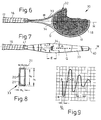
- a tennis racket 10 of known type shown in FIGS. 1 to 3 has an oval clamping frame 12 made of a correspondingly curved profile bar 13, which ends on both sides of the racket longitudinal axis M in - defining a plate-shaped heart 14 - profile arms 15.
- the latter are fixed in a handle 16 with a thickness i of 26 to 32 mm; the thickness i is measured on handles 16 without wrapping leather and without considering a handle cap 17.
- Tensioning frame 12 and heart 14 surround a stringing surface Q made of cross strings 18 and longitudinal strings 19 crossing them.
- the preferred point of impact for a tennis ball (not shown) is designated by S in FIG. 1.
- the tensioning frame 12 or its profiled bar 13 is rectangular in cross section, the side walls 20 of which run, for example, at a distance a of 7 mm and the transverse walls 21 of which run at a distance b of 17 mm.
- the outer width m is 11 mm and the outer height n is 21 mm. The latter is otherwise far lower than the thickness i of the handle 16.
- the natural frequency f o of the tennis racket 10 clamped in accordance with the diagram according to FIG. 5 can be measured by suddenly removing a force P acting on the longitudinal axis M of the racket.
- f O 3000 1 (HZ), where 1 is the oscillation length in mm read from the writing tape.
- FIG. 4 shows a longitudinal vibration curve for a conventional tennis racket 10 according to FIGS. 1 to 3.
- a ball touches the net of covering Q and forces the tenter 12 to follow the ball frequency. This movement seeks to counteract dynamic inertial forces of the tenter frame 12.
- Arrived at point B the ball reverses its direction and leaves the string Q following the ball approximately at point C.
- the design of a tennis racket 30 according to FIGS. 6 to 8 has a resonance frequency, which remedies the described defect;
- the cross section of the profile rod 33 contains the following dimensions according to FIG. 8: inner width a 1 8 mm, outer width m 1 10 mm, inner height b 1 32.2 mm, outer height n 1 37 mm as the result of a calculation which confirms the agreement of the natural frequency of this tennis racket 30 and the "ball resonance", that is to say the agreement of the excitation frequency with the natural frequency.
- the deflection d is a function of 1 J .
- FIG. 7 shows a frame shape that takes these findings into account, in which an area E with a projecting profile height n 1 extends on both sides of a frame web 34. From the area E, the profile height n o to the head 40 on the one hand and to the handle attachment 41 decreases continuously.
- the frame web 34 shown in section in FIG. 7 replaces the previously described heart 14 and has a lower average profile height h than the profile bar 33.
- the vibration behavior of the tennis racket 30 according to the invention in the longitudinal direction can be seen in FIG. 9.
- the natural frequency of the racket now matches the excitation frequency of the ball.
- the tennis racket 30 has reached point C or in the immediate vicinity thereof, and the ball receives, in addition to an additional acceleration, the tension frame 32 of the tennis racket 30 an exact trajectory which is no longer falsified by the dimension Z of the deflection, as can be seen in FIG. 4.
- a torsional vibration occurs about the longitudinal axis M. This torsional vibration is superimposed on the longitudinal vibration.
- the entire tennis racket 30 only vibrates sinusoidally at a frequency when touching the ball and also compensates for torsional deflection by timely swinging back.
- the handles 16 of the tennis racket 30 (FIGS. 6 to 8) and the embodiments 30 a and 30 b shown in FIGS. 10, 11 are of conventional thickness i, which - as said - measures 23 to 32 mm compared to this Thickness i have the adjoining profile bars - better designated as frame profiles 33 for the sake of their changing heights - in all cases a longer outer height n 1 .
- the max. Height n 1 of frame profile 33 a ends approximately at heart zone H and decreases as height n o to racket head 40.
Abstract
Description
Die Erfindung betrifft einen Schläger für Ballspiele, insbesondere einen Tennisschläger, mit in einem Spannrahmen aus einem Profilstab vorgesehener Bespannung in einer Ebene, einer an den spannrahmen anschließenden Herzzone mit flankierenden Profilstababschnitten des Spannrahmens und einem diese Profilstababschnitte verbindenden Rahmenteil, wobei die Profilstababschnitte mit dem Rahmenteil ein offenes Herzbegrenzen, sowie mit einem endwärtigen Handgriff in der Schlägerlängsachse, insbesondere in der Symmetrieachse.The invention relates to a racket for ball games, in particular a tennis racket, with covering provided in a tensioning frame made of a profile bar in one plane, a heart zone adjoining the tensioning frame with flanking profile bar sections of the tensioning frame and a frame part connecting these profile bar sections, the profile bar sections with the frame part open heart boundaries, as well as with an end handle in the longitudinal axis of the racket, in particular in the axis of symmetry.
Ein Tennisschläger mit einem plattenartigen Rahmenteil ist der DE-A-30 18 354 zu entnehmen, einen Rahmensteg zwischen Profilabschnitten zeigt DE-A-29 08 872. Die Dicke des nicht ummantelten Handgriffes solcher Tennisschläger mißt zwischen 23 und 32 mm, und die Höhe des Spannrahmens -- in Schlagrichtung, also rechtwinklig zur Bespannung gesehen -- liegt unterhalb der Handgriffdicke.A tennis racket with a plate-like frame part can be found in DE-A-30 18 354, a frame bridge between profile sections shows DE-A-29 08 872. The thickness of the uncovered handle of such tennis rackets measures between 23 and 32 mm, and the height of the Tensioning frame - seen in the direction of impact, i.e. at right angles to the covering - is below the handle thickness.
An derartigen -- im Bereich des Handgriffes eingespannten --Tennisschlägern dieser Art wurde durch Versuche eine Eigenfrequenz von 25 bis max. 50 Hz festgestellt; unbespannte Tennisschläger zeigen im allgemeinen geringfügig höhere Werte an.On such - clamped in the area of the handle - tennis rackets of this type, a natural frequency of 25 to max. 50 Hz detected; unstrung tennis rackets generally show slightly higher values.
Ein auf die Bespannung treffender Ball zwingt den Spannrahmen bekanntlich aus der Längsachse des Schlägers und führt zu einer Verschlechterung der Treffsicherheit; die beschriebene Auslenkung des Spannrahmens ist für die Richtung des Balles mit verantwortlich.As is known, a ball hitting the covering forces the tenter frame out of the longitudinal axis of the racket and leads to a deterioration in the accuracy; the described deflection of the tenter is responsible for the direction of the ball.
Durch die unterschiedlichen Maße der Eigenfrequenz des Tennisschlägers einerseits sowie der "Ballresonanz" von etwa 125 Hz anderseits entstehen über die gesamte Länge eines Spielfeldes nachweislich Abweichungen bis zu einem Meter von der gewünschten Fluglinie des Balles. Die Schlagpräzision bekannter Tennisschläger läßt somit erheblich zu wünschen übrig.Due to the different dimensions of the natural frequency of the tennis racket on the one hand and the "ball resonance" of approximately 125 Hz on the other hand, there are demonstrable deviations of up to one meter from the desired airline of the ball over the entire length of a playing field. The precision of known tennis rackets leaves much to be desired.
In der US-A-15 39 019 wird die Entwicklung eines Tennisschlägers beschrieben, dessen Schwingungsmittelpunkt im Zentrum der Bespannungsfläche liegt. Sein Handgriff setzt sich bis zum Schlägeroval in einer "intermediate portion" fort, deren -- zur Verminderung des Luftwiderstandes -- ovaler Querschnitt nahe des Schlägerrahmens knotenartig höher ausgebildet ist als dessen Querschnitt. Der Schlägerkopf ist an seinem Kopfende durch einen größeren Querschnitt schwerer gestaltet und durch ein Zusatzgewicht in Form eines Metallstreifens ergänzt.US-A-15 39 019 describes the development of a tennis racket whose center of vibration lies in the center of the stringing surface. Its handle continues up to the racket oval in an "intermediate portion", whose - to reduce the air resistance - the oval cross-section near the racket frame is knotted higher than its cross-section. The club head is heavier at the head end due to a larger cross-section and supplemented by an additional weight in the form of a metal strip.
In US-A-4 176 841 werden die Nachteile eines Schlägers durch das Auslenken seines Rahmens in Schlagrichtung erörtert, und dann wird die Aufgabe gestellt, einen in Massenproduktion erzeugbaren Tennisschläger aus Metall so zu gestalten, daS Billigsaiten geringer Elastizität ohne zusätzliche Federbelastung eingesetzt werden können. Es wird ein solcher Schläger mit vom Handgriff umgebenem Profilende gezeigt und als eine typische Profilweite, die über die Profillänge stets konstant bleibt, mit 22,5 mm angegeben. Zudem wird die Wanddicke für ein Hohlprofil aus einer wenigstens 95%-igen, bevorzugt 100%-igen, Titanlegierung mit 0,6 bis 0,8 mm angegeben. Da die gleichbleibende Profilweite 25- bis 40-fach -- insbesondere 30-fach -- und die profildicke 5- bis 20-fach, insbesondere 10-fach, größer sein kann als jene Wanddicke, ergeben sich rechnerisch verhältnismäßig hohe Werte für die Profilhöhe. Diese Höhenwerte bedingen aber bei diesem beschriebenen Schläger gleichzeitig eine bedeutende Gewichtszunahme, die ihn bei größeren Profilhöhen unspielbar werden läßt - kein Grund für einen Fachmann, derartige Wege zu bestreiten.US-A-4 176 841 discusses the disadvantages of a racket by deflecting its frame in the direction of the stroke, and then the object is to design a mass-produced metal tennis racket so that low elasticity strings can be used without additional spring loading . Such a racket is shown with the profile end surrounded by the handle and given as a typical profile width, which always remains constant over the profile length, with 22.5 mm. In addition, the wall thickness for a hollow profile made of at least 95%, preferably 100%, titanium alloy is given as 0.6 to 0.8 mm. Since the constant profile width can be 25 to 40 times - in particular 30 times - and the profile thickness 5 to 20 times, in particular 10 times, larger than that wall thickness, comparatively high values for the profile height result. These height values, however, at the same time cause a significant weight gain in the case of the racket described, which makes it unplayable at higher profile heights - no reason for a person skilled in the art to take such paths.
Angesichts dieser Gegebenheiten hat sich der Erfinder das Ziel gesetzt, bei einem Schläger der eingangs erwähnten Art die beschriebenen Abweichungen erheblich zu vermindern und sein Schlagverhalten insgesamt zu verbessern. Vor allem soll die Profilsteifigkeit erhöht werden.In view of these circumstances, the inventor has set himself the goal of significantly reducing the described deviations in a racket of the type mentioned at the beginning and of improving its impact behavior overall. Above all, the profile stiffness should be increased.
Zur Lösung dieser Aufgabe führt, daß die quer zur Ebene der Bespannung verlaufende größte Querschnittshöhe des Profilstabes beidseits der Schlägerlängsachse im Bereich der Herzzone größer ist als die Dicke des Handgriffes, wobei die Querschnittshöhe des Profilstabes etwa von der Herzzone des Schlägers zu dessen Schlägerkopf hin abnimmt. Es hat sich gezeigt, daß eine solche Erhöhung des Profilstabquerschnittes -- vor allem beidseits der Schlägerlängsachse, also in den Seitenbereichen des Rahmens -- den Schläger steifer werden läßt und sein Schlagverhalten erheblich verbessert.To achieve this object, the greatest cross-sectional height of the profile bar running transversely to the plane of the covering on both sides of the longitudinal axis of the racket in the area of the heart zone is greater than the thickness of the handle, the cross-sectional height of the profile bar decreasing approximately from the heart zone of the racket to the club head. It has been shown that such an increase in the profile bar cross-section - especially on both sides of the longitudinal axis of the racket, that is to say in the side regions of the frame - makes the racket stiffer and significantly improves its impact behavior.
Besondere Ausführungssaiten der Erfindung sind in den Ansprüchen 2 bis 10 dargelegt.Particular embodiment strings of the invention are set out in claims 2 to 10.
Bei dem Schläger nach der Erfindung liegt die übliche Dicke des Handgriffes ohne Ummantelung - also ohne Griffleder, Schaumgummiumhüllung od. dgl. nicht zum konstruktiven Schlägerprofil gehörenden Zutaten - und ohne Berücksichtigung der Griffkappe zwischen etwa 23 und 32 mm. Seine Schlägerachse bildet eine Symmetriegerade, und die Höhe des Querschnittes des Spannrahmens ist - unbeschadet der Rahmengestaltung außerhalb des angegebenen Bereiches in diesem - größer als jene Dicke des Handgriffes. Letztere ist durch die menschliche Hand vorgegeben und bleibt deshalb selbst ohne Einfluß auf die Schlägergestaltung. Erfindungsgemäß gilt die voranstehende Maßgabe des Verhältnisses von Handgriffdicke zu der Höhe eines Querschnittes auch für eine Profilstab, aus welchem der Spannrahmen hergestellt ist.In the racket according to the invention, the usual thickness of the handle without casing - that is, without grip leather, foam rubber covering or the like. Components not belonging to the structural racket profile - and without taking into account the grip cap, is between about 23 and 32 mm. Its racket axis forms a line of symmetry, and the height of the cross section of the tenter frame is - without prejudice to the frame design outside the specified area in this - greater than that thickness of the handle. The latter is determined by the human hand and therefore remains without influence on the club design. According to the invention, the above stipulation of the ratio of handle thickness to the height of a cross section also applies to a profile rod from which the stenter frame is made.
Als bevorzugte max. Höhe des Querschnittes von Profilstab und/oder Spannrahmen hat sich ein Maß über der Dicke des Handgriffes bis zu etwa 45 mm erwiesen.The preferred max. The height of the cross-section of the profile bar and / or stenter has proven to be a measure of the thickness of the handle up to about 45 mm.
Als günstig hat es sich erwiesen, daß sich der Schläger von der größten Querschnittshöhe seines Profilstabes im Bereich der Herzzone sowohl zum Handgriff als auch zum Schlägerkopf, also in beide Richtungen der Längsachse, verjüngt. Bei einer bevorzugten Ausführungsform soll die größte Höhe des Profilstabes im angegebenen Bereich in der Nähe der Verbindungsstelle von Profilstab und Rahmensteg liegen, vorteilhafterweise beidseits dieses Rahmensteges. Auch ist von Vorteil, wenn diese größte Höhe in einem beidseits der Herzzone verlaufenden Bereich gleichbleibend verläuft.It has proven to be advantageous that the racket tapers from the greatest cross-sectional height of its profile bar in the area of the heart zone both to the handle and to the racket head, that is to say in both directions of the longitudinal axis. In a preferred embodiment, the greatest height of the profiled bar in the specified area should be in the vicinity of the connection point between the profiled bar and the frame web, advantageously on both sides of this frame web. It is also advantageous if this greatest height is constant in an area running on both sides of the heart zone.
Die Abnahme der größten Höhe mag unter Erzeugung einer geraden Längskontur des Profiles stetig erfolgen, jedoch ist es auch möglich, die Kontur geschwungen oder gekrümmt herzustellen.The greatest height may decrease steadily while creating a straight longitudinal contour of the profile, but it is also possible to produce the contour curved or curved.
Erfindungsgemäß nimmt die senkrecht zur Bespannung gerichtete Höhe des Querschnittes oder Profiles von Schläger bzw. Spannrahmen gegenüber der Griffdicke sprunghaft oder allmählich zu und kann von der Stelle des höchsten Ausmaßes zum Schlägerkopf hin - ebenfalls sprunghaft oder allmählich - wieder abnehmen.According to the invention, the height of the cross-section or profile of the racket or stenter, which is perpendicular to the covering, increases abruptly or gradually compared to the grip thickness and can also decrease again from the point of greatest extent to the racket head.
Der erfindungsgemäße Schläger - der insoweit mit bekannten Schlägern übereinstimmt, als sein Spannrahmen bzw. ein diesen ergebender Profilstab eine in der Ebene der Bespannung gemessene Querschnittsbreite zwischen 8 und 16 mm besitzt - weist ein Trägheitsmoment auf, welches 4- bis 16fach höher ist als das Trägheitsmoment eines Tennisschlägers nach dem Stande der Technik, dessen Querschnittshöhe gleich oder geringer ist als die Dicke seines Handgriffes.The racket according to the invention - which corresponds to known rackets insofar as its tenter frame or a profile rod resulting from this has a cross-sectional width between 8 and 16 mm measured in the plane of the covering - has an moment of inertia which is 4 to 16 times higher than the moment of inertia a tennis racket according to the prior art, the cross-sectional height of which is equal to or less than the thickness of its handle.
Soweit vorstehend ein Querschnittsmaß erwähnt wird, bleibt zu berücksichtigen, daß die Längsachse des Schlägers auch Symmetrieachse ist, d.h. dem beschriebenen Querschnitt des Spannrahmens liegt auf der anderen Seite der Symmetrieachse ein entsprechender Querschnitt gegenüber. Zudem bestimmt die Bespannung eine Symmetrieebene.Insofar as a cross-sectional dimension is mentioned above, it must be taken into account that the longitudinal axis of the racket is also an axis of symmetry, ie the cross-section of the clamping frame described is on the other side of the axis of symmetry a corresponding cross-section. In addition, the covering determines a plane of symmetry.
Weitere Vorteile, Merkmale und Einzelheiten der Erfindung ergeben sich aus der nachfolgenden Beschreibung sowie anhand der Zeichnung; diese zeigt in:
- Fig. 1:
- die teilweise wiedergegebene Draufsicht auf einen bekannten Tennisschläger mit Spannrahmen aus Profilrohr;
- Fig. 2:
- die Seitenansicht zu Fig. 1;
- Fig. 3:
- den vergrößerten Querschnitt durch Fig. 1 nach deren Linie III - III;
- Fig. 4:
- eine Schwingungsgrafik für den Tennisschläger nach Fig. 1 bis 4;
- Fig. 5:
- eine Schemaskizze zu einem Belastungsfall;
- Fig. 6:
- eine Teildraufsicht auf eine bevorzugte Ausführungsform eines erfindungsgemäßen Tennisschlägers mit Spannrahmen;
- Fig. 7:
- die der Fig. 2 entsprechende Darstellung des Tennisschlägers der Fig. 6;
- Fig. 8:
- einen Querschnitt des Spannrahmens des erfindungsgemäßen Tennisschlägers;
- Fig. 9:
- eine Schwingungsgrafik zu Fig. 6 bis 8;
- Fig.10,11:
- schematisierte Seitenansichten zu ausgewählten bevorzugten Ausführungsformen des erfindungsgemäßen Tennisschlägers.
- Fig. 1:
- the partially reproduced top view of a known tennis racket with a frame made of profile tube;
- Fig. 2:
- the side view of Fig. 1;
- Fig. 3:
- the enlarged cross section through Figure 1 along the line III - III.
- Fig. 4:
- a vibration diagram for the tennis racket of Figures 1 to 4.
- Fig. 5:
- a schematic sketch of an exposure case;
- Fig. 6:
- a partial plan view of a preferred embodiment of a tennis racket with tensioning frame according to the invention;
- Fig. 7:
- the representation corresponding to FIG. 2 of the tennis racket of FIG. 6;
- Fig. 8:
- a cross section of the frame of the tennis racket according to the invention;
- Fig. 9:
- a vibration graph to Figures 6 to 8.
- Fig. 10,11:
- schematic side views of selected preferred embodiments of the tennis racket according to the invention.
Ein in den Fig. 1 bis 3 besipielhaft dargestellten Tennisschläger 10 bekannter Art weist einen ovalen Spannrahmen 12 aus einem entsprechend gekrümmten Profilstab 13 auf, der beidseits der Schlägerlängsachse M in - ein plattenförmiges Herz 14 begrenzenden - Profilarmen 15 endet. Letztere sind in einem Handgriff 16 einer Dicke i von 26 bis 32 mm festgelegt ; die Dicke i ist an Handgriffen 16 ohne Umwicklungsleder und ohne Berücksichtigung einer Griffkappe 17 gemessen.A
Spannrahmen 12 und Herz 14 umgeben eine Bespannungsfläche Q aus Quersaiten 18 und diese kreuzenden Längssaiten 19. Der bevorzugte Auftreffpunkt für einen nicht gezeigten Tennisball ist in Fig. 1 mit S bezeichnet.Tensioning
Der Spannrahmen 12 bzw. sein Profilstab 13 ist gemäß Fig. 3 rechteckigen Querschnitts, dessen Seitenwände 20 beispielsweise in einem Abstand a von 7 mm und dessen Querwände 21 in einem Abstand b von 17 mm verlaufen.According to FIG. 3, the
Bei einer Wanddicke q der Seiten- bzw. Querwand 20 bzw. 21 von 2 mm ergeben sich eine Außenbreite m von 11 mm und eine äußere Höhe n von 21 mm. Letztere ist im übrigen weit niedriger als die Dicke i des Handgriffs 16.With a wall thickness q of the side or
Die aus vorstehenden Maßen errechenbare Querschnittsfläche 0für den Profilstab 13 beträgt in mm2:![]()
![]()
Die Eigenfrequenz fo des entsprechend dem Schema gemäß Fig. 5 eingespannten Tennisschlägers 10 ist meßbar, indem eine an der Schlägerlängsachse M angreifende Kraft P plötzlich entfernt wird.The natural frequency f o of the
Wird die Eigenfrequenz auf ein mit 3000 mm/s laufendes Schreibband geschrieben, gilt![]()
![]()
Im Elastizitätsbereich ist das Maß d der in Fig. 5 deutlich gemachten Durchbiegung der Kraft P proportional. Sie ist aber auch in eine Beziehung zu der Eigenfrequenz des Tennisschlägers 10 in Längsrichtung zu bringen; hat ein Tennisschläger unter der gleichen Kraft P eine Durchbiegung von d1 und ein anderer eine solche von d2, kann die Eigenfrequenz des zweiten Tennisschlägers annähernd nach folgender Beziehung berechnet werden:
Die Kontaktzeit zwischen Tennisschläger 10 und Ball wurde durch viele Versuche - u. a. durch Hochgeschwindigkeitsfotografie - mit 2 bis max. 6 ms festgestellt, im Mittel also mit 4 ms, was für eine ganze Schwingung t = 8 ms oder 125 Hz erbringt.The contact time between
Fig. 4 zeigt eine Schwingungskurve in Längsrichtung für einen üblichen Tennisschläger 10 nach Fig. 1 bis 3. Bei Punkt A berührt ein Ball das Netz der Bespannung Q und zwingt den Spannrahmen 12, der Ballfrequenz zu folgen. Dieser Bewegung trachten dynamische Trägheitskräfte des Spannrahmens 12 entgegenzuwirken. Am Punkt B angelangt, kehrt der Ball seine Richtung um und verläßt die dem Ball folgende Bespannung Q etwa an Punkt C. Der Tennisschläger 10 schwingt in seiner Eigenfrequenz nach und befindet sich erst am Punkt D, wenn sich der Ball von der Bespannung Q bei C trennt (t = 8 ms, t/4 = 2 ms).FIG. 4 shows a longitudinal vibration curve for a
Die unterschiedlichen Maße der Eigenfrequenz des Tennisschlägers 10 von 25 bis 50 Hz einerseits sowie der Erregerfrequenz des Balles von etwa 125 Hz anderseits führen - über die ganze Länge eines Spielfeldes gesehen - zu bedeutenden Abweichungen des Balles von der gewünschten Fluglinie ; diese Abweichung kann - wie erwähnt - bis zu einem Meter betragen.The different dimensions of the natural frequency of the
Die Ausführung eines Tennisschlägers 30 nach Fig. 6 bis 8 weist ein Resonanzfrequenz auf, welche dem beschriebenen Mangel abhilft ; der Querschnitt des Profilstabes 33 enthält gemäß Fig. 8 die folgenden Maße:
Die errechenbare Querschnittsfläche ist hier![]()
Bei
- d10 =
- Durchbiegung von TS10
- d30 =
- Durchbiegung Tennisschläger 30 (TS30)
- FR10 =
- Eigenresonanz von TS10 = 50 Hz*)
- FR30 =
- Eigenresonanz von TS30 = 125 Hz

Fußnote : *) Werte gelten für Graphitschläger, also für harte WerkstoffeThe calculable cross-sectional area is here
At
- d 10 =
- Deflection of TS 10
- d 30 =
- Deflection tennis racket 30 (TS 30 )
- FR 10 =
- Natural resonance of TS 10 = 50 Hz *)
- FR 30 =
- Natural resonance of TS 30 = 125 Hz
Footnote: *) Values apply to graphite mallets, i.e. hard materials
Die Einfederung unter einer Last P muß - gegenüber TS10 - bei TS30 1/6 betragen. Die Querschnittsflächen in Fig. 3 und Fig. 5 führen zu
Die Durchbiegung d ist eine Funktion von ![]()
![]()
Das heißt![]()
![]()
Die Resonanzfrequenz ist![]()
![]()
Nimmt man an
b1 = 37 mm,
n1 = 42 mm,
so ist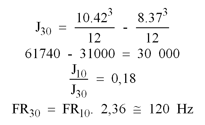
b 1 = 37 mm,
n 1 = 42 mm,
so is
Eine diese Erkenntnisse berücksichtigende Rahmenform gibt Fig. 7 wieder, in der sich ein Bereich E mit vorstehender Profilhöhe n1 beidseits eines Rahmensteges 34 erstreckt. Vom Bereich E nimmt die Profilhöhe no zum Schlagerkopf 40 einerseits und zum Handgriffansatz 41 stetig ab. Der in Fig. 7 geschnitten dargestellte Rahmensteg 34 ersetzt das zuvor beschriebene Herz 14 und weist eine geringere mittlere Profilhöhe h auf als der Profilstab 33.FIG. 7 shows a frame shape that takes these findings into account, in which an area E with a projecting profile height n 1 extends on both sides of a
Das Schwingungsverhalten des erfindungsgemäßen Tennisschlägers 30 in Längsrichtung entnimmt man Fig. 9. Mit dessen Eigenfrequenz stimmt jetzt die Erregerfrequenz des Balles überein. Bei dessen Abheben von der Bespannung Q ist der Tennisschläger 30 am Punkt C oder in dessen unmittelbarer Nachbarschaft angelangt, und der Ball erhält neben einerzusätzlichen Beschleunigung aus dem Spannrahmen 32 des Tennisschlägers 30 eine genaue Flugbahn, die nicht mehr durch das Maß Z der Auslenkung verfälscht ist, wie sie Fig. 4 erkennen läßt. Bei ungenau - d. h. außerhalb der Längsachse M auf den Tennisschläger 30 bzw. dessen Bespannung Q - treffenden Bällen entsteht eine Torsionsschwingung um die Längsachse M. Diese Torsionsschwingung ist der Längsschwingung überlagert.The vibration behavior of the
Wird auch diese Schwingung durch Abstimmung des Rahmenstegs 34 aus Fig. 7 auf bevorzugt 125 Hz gebracht, schwingt der gesamte Tennisschläger 30 bei Ballberührung nur noch sinusförmig in einer Frequenz und kompensiert auch torsionsbedingte Schlagabweichungen durch rechtzeitiges Rückschwingen.If this vibration is also brought to preferably 125 Hz by tuning the
Die Handgriffe 16 des Tennisschlägers 30 (Fig. 6 bis 8) und der in den Fig. 10, 11 wiedergegebenen Ausführungsformen 30a und 30b sind von üblicher Dicke i, welche -- wie gesagt -- 23 bis 32 mm mißt, gegenüber dieser Dicke i besitzen die anschließenden Profilstäbe -- ihrer wechselnden Höhen halber besser als Rahmenprofile 33 bezeichnet -- in allen Fällen eine längere äußere Höhe n1.The
Die max. Höhe n1 von Rahmenprofil 33a (Fig. 10) endet etwa an Herzzone H und nimmt als Höhe no zum Schlägerkopf 40 ab.The max. Height n 1 of frame profile 33 a (FIG. 10) ends approximately at heart zone H and decreases as height n o to
Die in der Zeichnung dargestellten Ausführungsbeispiele zeigen von der max. Höhe n1 ausgehende Gerade, also jeweils eine stetige Abnahme der variablen Höhe no. Statt diesem stetigen Verlauf können die entsprechenden Querschnittskonturen auch gekrümmt sein, wie dies in Fig. 11 bei 33b angedeutet ist.The embodiments shown in the drawing show the max. Height n 1 outgoing straight line, i.e. a constant decrease in the variable height n o . Instead of this continuous course, the corresponding cross-sectional contours can also be curved, as indicated at 33 b in FIG. 11.
Claims (10)
- Racket (30) for ball games, in particular tennis racket, with strings in one plane provided in a clamping frame (32) consisting of a profile bar (33), a core zone (H) adjoining the clamping frame (32) and flanked by profile bar sections of the clamping frame (32), a frame portion (34) connecting these profile bar sections, the profile bar sections with the frame portion delimiting an open heart-shaped portion, and an end handle (16) in the longitudinal axis (M) of the racket, in particular in the plane of symmetry, characterised in that the maximum cross-sectional height (n1) of the profile bar (33, 33a, 33b) extending transversely to the plane of the strings (Q) on both sides of the longitudinal axis (M) in the region of the core zone (H), is greater than the thickness (i) of the handle (16), with a cross-sectional heigth (no) of the profile bar decreasing from approximately the racket core zone towards the racket head (40).
- Racket according to claim 1 with a frame web (34) as the frame portion connecting the profile sections, characterised in that a profile height (h) of the frame web (34) is shorter than the maximum height (n1) of the profile bar (33, 33a, 33b) in the region of the core zone (H).
- Racket according to claim 1 or 2, characterised in that the maximum cross-sectional height (n1) of the profile bar (33) in the region of the core zone (H) is provided at both ends of the frame web (34).
- Racket according to any of claim 1 to 3, characterised in that the maximum cross-sectional height (n1) of the profile bar (30, 30a, 30b) is constant in a region (E) of the core zone (H) on both sides of the longitudinal axis (M) of the racket.
- Racket according to any of claims 1 to 4, characterised in that the profile bar (33, 33b) decreases both towards the handle (16) and also towards the racket head (40).
- Racket according to any of claims 1 to 5, characterised in that the reduction in its cross-sectional height (n0) is constant, or that its height (n) decreases, giving a curved contour.
- Racket according to any of claims 1 to 6 characterised in that the profile bar (33, 33a, 33b) is in the form of a hollow profile.
- Racket according to any of claims 1 to 7, characterised in that the first-order resonant frequency of the stringed racket (30) approximately corresponds to the frequency converted from the half-oscillation of the period of ball/stringing (Q) contact, and is 80 to 200 Hz, in particular 100 to 140 Hz, in the case of the racket (30) fixed at the handle (16), for games with a ball in contact with the stringing (0) over a duration of approximately 2 to 6 ms for a half-oscillation.
- Racket according to claim 8, characterised in that the natural frequency of the racket (30) approximately concides with the excitation frequency of the ball.
- Racket according to any of claims 1 to 9 with a cross-sectional width of between 8 and 16 mm of the profile bar providing the clamping frame, characterised in that the moment of inertia of the cross-section of the clamping frame (32) or profile bar (33) of the racket (30) is 4 to 16 times the moment of inertia of a racket (10) of which the cross-sectional height is equal to or less than the thickness (i) of the handle (16).
Priority Applications (1)
| Application Number | Priority Date | Filing Date | Title |
|---|---|---|---|
| AT88202025T ATE63226T1 (en) | 1984-09-22 | 1985-09-17 | RACKETS FOR BALL GAMES, ESPECIALLY TENNIS RACKETS. |
Applications Claiming Priority (3)
| Application Number | Priority Date | Filing Date | Title |
|---|---|---|---|
| DE19843434956 DE3434956A1 (en) | 1984-09-22 | 1984-09-22 | BULLETS FOR GAMES WITH LIMITED ELASTIC BALL |
| DE3434956 | 1984-09-22 | ||
| EP85111713A EP0176021B1 (en) | 1984-09-22 | 1985-09-17 | Tennis racket |
Related Parent Applications (1)
| Application Number | Title | Priority Date | Filing Date |
|---|---|---|---|
| EP85111713.5 Division | 1985-09-17 |
Publications (4)
| Publication Number | Publication Date |
|---|---|
| EP0310169A2 EP0310169A2 (en) | 1989-04-05 |
| EP0310169A3 EP0310169A3 (en) | 1989-08-02 |
| EP0310169B1 EP0310169B1 (en) | 1991-05-08 |
| EP0310169B2 true EP0310169B2 (en) | 1996-08-07 |
Family
ID=25825035
Family Applications (1)
| Application Number | Title | Priority Date | Filing Date |
|---|---|---|---|
| EP88202025A Expired - Lifetime EP0310169B2 (en) | 1984-09-22 | 1985-09-17 | Rackets for ball games, especially tennis rackets |
Country Status (2)
| Country | Link |
|---|---|
| EP (1) | EP0310169B2 (en) |
| AT (1) | ATE63836T1 (en) |
Families Citing this family (2)
| Publication number | Priority date | Publication date | Assignee | Title |
|---|---|---|---|---|
| JPS63270068A (en) * | 1987-04-28 | 1988-11-08 | ヤマハ株式会社 | Racket frame |
| JPH06236311A (en) * | 1993-02-10 | 1994-08-23 | Matsushita Electric Ind Co Ltd | Information control unit |
Family Cites Families (3)
| Publication number | Priority date | Publication date | Assignee | Title |
|---|---|---|---|---|
| US1539019A (en) * | 1924-02-07 | 1925-05-26 | John P Nikonow | Tennis racket |
| US3647211A (en) * | 1970-06-08 | 1972-03-07 | James H Doessel | Plastic tennis racket having predetermined cross sections effecting flexibility |
| US4165071A (en) * | 1976-01-05 | 1979-08-21 | Frolow Jack L | Tennis racket |
-
1985
- 1985-09-17 AT AT85111713T patent/ATE63836T1/en not_active IP Right Cessation
- 1985-09-17 EP EP88202025A patent/EP0310169B2/en not_active Expired - Lifetime
Also Published As
| Publication number | Publication date |
|---|---|
| ATE63836T1 (en) | 1991-06-15 |
| EP0310169A2 (en) | 1989-04-05 |
| EP0310169A3 (en) | 1989-08-02 |
| EP0310169B1 (en) | 1991-05-08 |
Similar Documents
| Publication | Publication Date | Title |
|---|---|---|
| EP0176021B1 (en) | Tennis racket | |
| DE2042803C3 (en) | Tennis racket | |
| DE2546028A1 (en) | TENNIS RACKET | |
| EP1557204B1 (en) | Racquet for ball sports and method for manufacturing | |
| EP0443001B1 (en) | Racquets, especially tennis racquets | |
| DE4037568A1 (en) | TENNIS RACKET | |
| DE10308532B3 (en) | Rackets for ball games | |
| EP0310169B2 (en) | Rackets for ball games, especially tennis rackets | |
| EP1557203B1 (en) | Racquet for ball sports and method for its manufacture | |
| DE4022187A1 (en) | RACKET FOR BALL GAMES | |
| EP0181319B1 (en) | Tennis racket | |
| DE102006004863B4 (en) | Racket for ball games | |
| EP1097730B1 (en) | Racket for ball games | |
| DE3702197C2 (en) | Tennis racket | |
| EP0487963B1 (en) | Tennis racket | |
| DE2804569C3 (en) | Frame for a racket | |
| EP0468263A1 (en) | Racket for ball games, especially tennis racket | |
| DE4495735B4 (en) | Balancing counterweight system for rackets for ball games | |
| EP1452209B1 (en) | Racket for ball sports | |
| DE3910871A1 (en) | Racket for ball games, especially tennis racket | |
| DE4031180A1 (en) | RACKETS, ESPECIALLY TENNIS, SQUASH, BADMINTON OR RACKETBALL RACKETS | |
| DE8405048U1 (en) | Tennis racket | |
| AT404230B (en) | BALL RACKET | |
| DE2417439C3 (en) | Frame for a tennis racket | |
| DE2417439B2 (en) | FRAME FOR A TENNIS RACKET |
Legal Events
| Date | Code | Title | Description |
|---|---|---|---|
| PUAI | Public reference made under article 153(3) epc to a published international application that has entered the european phase |
Free format text: ORIGINAL CODE: 0009012 |
|
| 17P | Request for examination filed |
Effective date: 19880916 |
|
| AC | Divisional application: reference to earlier application |
Ref document number: 176021 Country of ref document: EP |
|
| AK | Designated contracting states |
Kind code of ref document: A2 Designated state(s): AT BE CH DE FR GB IT LI NL SE |
|
| PUAL | Search report despatched |
Free format text: ORIGINAL CODE: 0009013 |
|
| AK | Designated contracting states |
Kind code of ref document: A3 Designated state(s): AT BE CH DE FR GB IT LI NL SE |
|
| 17Q | First examination report despatched |
Effective date: 19900327 |
|
| GRAA | (expected) grant |
Free format text: ORIGINAL CODE: 0009210 |
|
| ITF | It: translation for a ep patent filed |
Owner name: DE DOMINICIS & MAYER S.R.L. |
|
| AC | Divisional application: reference to earlier application |
Ref document number: 176021 Country of ref document: EP |
|
| AK | Designated contracting states |
Kind code of ref document: B1 Designated state(s): AT BE CH DE FR GB IT LI NL SE |
|
| REF | Corresponds to: |
Ref document number: 63226 Country of ref document: AT Date of ref document: 19910515 Kind code of ref document: T |
|
| GBT | Gb: translation of ep patent filed (gb section 77(6)(a)/1977) | ||
| REF | Corresponds to: |
Ref document number: 3582805 Country of ref document: DE Date of ref document: 19910613 |
|
| ET | Fr: translation filed | ||
| PLBI | Opposition filed |
Free format text: ORIGINAL CODE: 0009260 |
|
| 26 | Opposition filed |
Opponent name: DONNAY INDUSTRIES S.A. Effective date: 19920207 Opponent name: DUNLOP LIMITED Effective date: 19920206 |
|
| NLR1 | Nl: opposition has been filed with the epo |
Opponent name: DONNAY INDUSTRIES S.A. Opponent name: DUNLOP LIMITED |
|
| PLAB | Opposition data, opponent's data or that of the opponent's representative modified |
Free format text: ORIGINAL CODE: 0009299OPPO |
|
| R26 | Opposition filed (corrected) |
Opponent name: DUNLOP LIMITED * 920207 DONNAY INDUSTRIES S.A. Effective date: 19920206 |
|
| PLAB | Opposition data, opponent's data or that of the opponent's representative modified |
Free format text: ORIGINAL CODE: 0009299OPPO |
|
| R26 | Opposition filed (corrected) |
Opponent name: DUNLOP LIMITED * 920207 DONNAY INDUSTRIES S.A. Effective date: 19920206 |
|
| PGFP | Annual fee paid to national office [announced via postgrant information from national office to epo] |
Ref country code: DE Payment date: 19940927 Year of fee payment: 10 |
|
| EAL | Se: european patent in force in sweden |
Ref document number: 88202025.8 |
|
| PG25 | Lapsed in a contracting state [announced via postgrant information from national office to epo] |
Ref country code: DE Effective date: 19950223 |
|
| PLAW | Interlocutory decision in opposition |
Free format text: ORIGINAL CODE: EPIDOS IDOP |
|
| PUAH | Patent maintained in amended form |
Free format text: ORIGINAL CODE: 0009272 |
|
| STAA | Information on the status of an ep patent application or granted ep patent |
Free format text: STATUS: PATENT MAINTAINED AS AMENDED |
|
| 27A | Patent maintained in amended form |
Effective date: 19960807 |
|
| AK | Designated contracting states |
Kind code of ref document: B2 Designated state(s): AT BE CH DE FR GB IT LI NL SE |
|
| REG | Reference to a national code |
Ref country code: CH Ref legal event code: AEN Free format text: AUFRECHTERHALTUNG DES PATENTES IN GEAENDERTER FORM |
|
| PGFP | Annual fee paid to national office [announced via postgrant information from national office to epo] |
Ref country code: SE Payment date: 19960920 Year of fee payment: 12 |
|
| PGFP | Annual fee paid to national office [announced via postgrant information from national office to epo] |
Ref country code: NL Payment date: 19960923 Year of fee payment: 12 |
|
| NLR2 | Nl: decision of opposition | ||
| PGFP | Annual fee paid to national office [announced via postgrant information from national office to epo] |
Ref country code: BE Payment date: 19961003 Year of fee payment: 12 |
|
| GBTA | Gb: translation of amended ep patent filed (gb section 77(6)(b)/1977) |
Effective date: 19891224 |
|
| ITF | It: translation for a ep patent filed |
Owner name: DE DOMINICIS & MAYER S.R.L. |
|
| ET3 | Fr: translation filed ** decision concerning opposition | ||
| NLR3 | Nl: receipt of modified translations in the netherlands language after an opposition procedure | ||
| PGFP | Annual fee paid to national office [announced via postgrant information from national office to epo] |
Ref country code: CH Payment date: 19961230 Year of fee payment: 12 |
|
| PG25 | Lapsed in a contracting state [announced via postgrant information from national office to epo] |
Ref country code: SE Free format text: LAPSE BECAUSE OF NON-PAYMENT OF DUE FEES Effective date: 19970918 |
|
| PG25 | Lapsed in a contracting state [announced via postgrant information from national office to epo] |
Ref country code: LI Free format text: LAPSE BECAUSE OF NON-PAYMENT OF DUE FEES Effective date: 19970930 Ref country code: CH Free format text: LAPSE BECAUSE OF NON-PAYMENT OF DUE FEES Effective date: 19970930 Ref country code: BE Free format text: LAPSE BECAUSE OF NON-PAYMENT OF DUE FEES Effective date: 19970930 |
|
| BERE | Be: lapsed |
Owner name: KUEBLER SIEGFRIED Effective date: 19970930 |
|
| PG25 | Lapsed in a contracting state [announced via postgrant information from national office to epo] |
Ref country code: NL Free format text: LAPSE BECAUSE OF NON-PAYMENT OF DUE FEES Effective date: 19980401 |
|
| REG | Reference to a national code |
Ref country code: CH Ref legal event code: PL |
|
| NLV4 | Nl: lapsed or anulled due to non-payment of the annual fee |
Effective date: 19980401 |
|
| EUG | Se: european patent has lapsed |
Ref document number: 88202025.8 |
|
| REG | Reference to a national code |
Ref country code: GB Ref legal event code: IF02 |
|
| PGFP | Annual fee paid to national office [announced via postgrant information from national office to epo] |
Ref country code: GB Payment date: 20040922 Year of fee payment: 20 |
|
| PGFP | Annual fee paid to national office [announced via postgrant information from national office to epo] |
Ref country code: FR Payment date: 20040923 Year of fee payment: 20 |
|
| PGFP | Annual fee paid to national office [announced via postgrant information from national office to epo] |
Ref country code: AT Payment date: 20041231 Year of fee payment: 20 |
|
| PG25 | Lapsed in a contracting state [announced via postgrant information from national office to epo] |
Ref country code: GB Free format text: LAPSE BECAUSE OF EXPIRATION OF PROTECTION Effective date: 20050916 |
|
| REG | Reference to a national code |
Ref country code: GB Ref legal event code: PE20 |
|
| PLAB | Opposition data, opponent's data or that of the opponent's representative modified |
Free format text: ORIGINAL CODE: 0009299OPPO |